1. DAY
In the following photos you can see the assignment of the Echo World botton in Designing Electronics, we could understand and some Principles of the Attiny 44 , for connecting the Pins with the other Components. In this assignment we wanted to understand the logic and function of back of the microcontroller. In the first part we have to understand what we have to consider for programming the board. And look a little bit more the anatomy of the microcontroller ATTiNY 44.
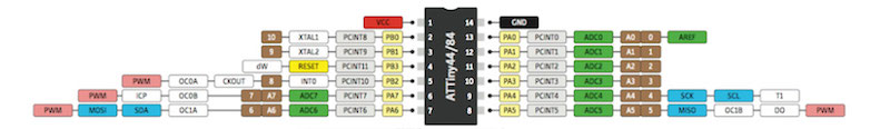
ANALYZING THE DATA SHEET
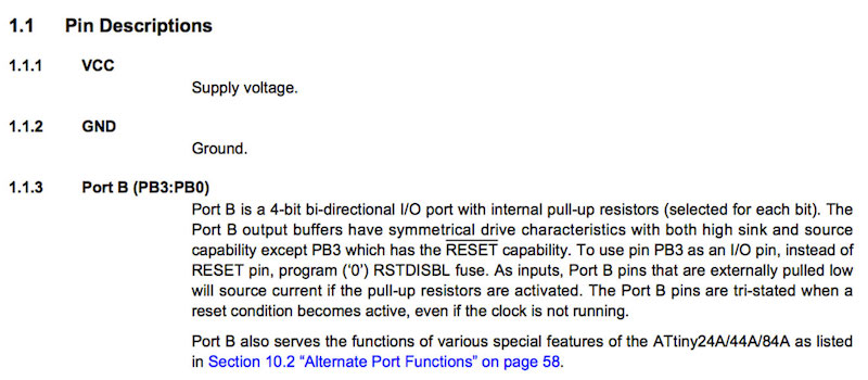
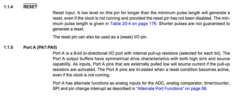
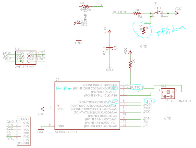
In the datasheet you can find the information of the Pins description and look exactly the pins that we will use. Also what is his function and ans for Example the pins that we can use as I/O for example the Port A. PDIP/ SOIC: The Pins that we need to connect with the Arduino are the VCC GND, Reet Mosi SCK MISO, we designed in our Hallo Welt the socket for this component in a 6 Pin Header. In this case I connected in the arduino the same connection that I did for the previous programming for the LSG flower.
In the previously photos you can see the assignment of the Echo World botton in Designing Electronics, we could understand and some Principles of the Attiny 44 , for connecting the Pins with the other Components. In this assignment we wanted to understand the logic and function of back of the microcontroller. In the first part we have to understand what we have to consider for programming the board. And look a little bit more the anatomy of the microcontroller ATTiNY 44.
ANALYZING THE DATA SHEET In the datasheet you can find the information of the Pins description and look exactly the pins that we will use. Also what is his function and ans for Example the pins that we can use as I/O for example the Port A. PDIP/ SOIC: The Pins that we need to connect with the Arduino are the VCC GND, Reet Mosi SCK MISO, we designed in our Hallo Welt the socket for this component in a 6 Pin Header.
In this case I connected in the arduino the same connection that I did for the previous programming for the LSG flower. PROGRAMMING In the programming you have to take care which are the pins for I/O that correspond to the Arduino IDE. Now we can proceed to uploading the programming of the Arduino in order to use the arduino as ISP. Remember to install the Attiny supporting, opening the preferences spanner in arduino program >
“Additional Boards Manager URLs” > https://raw.githubusercontent.com/damellis/attiny/ide-1.6.x-boards-manager/package_damellis_attiny_index.json Click the OK button to save your updated preferences Open the board's manager in the “Tools > Board” menu.
It should look as shown in the picture: In the following part you have to program the arduino as ISP using the sketch that you can find in the library: FILE> EXAMPLES> ARDUINO ISP.
Good, after uploading the program you can program your board: In this case you can see the serial in the panel TOOls> ATtiny and the diffrent boards Please select the ATtiny44 (external 20 MHz clock)
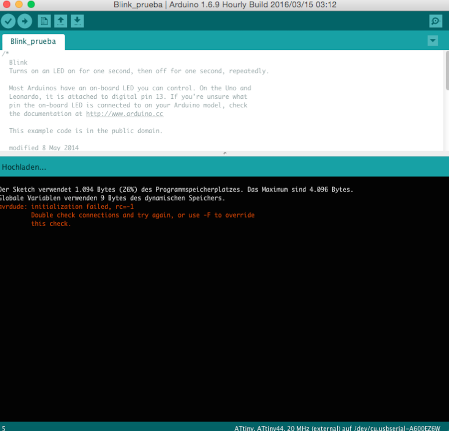
Serial port from the arduino Programmer : Arduino as ISP And upload the code!! Here was the critical point, I couldn't upload the program :S
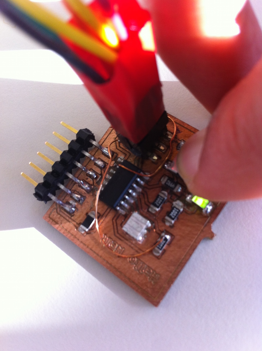
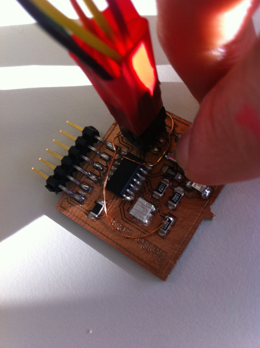
I received this message as you can see in the pictures: It looks that it happened not only to me but also to my Fab Academy classmates. After one day trying to find the errors in the components resistors and also trying to see if something was wrong in the connections, Tobias Pope, my classmate from Fab Lab Bottrop, helped me to verify the eagle file, and we found a fatal error,
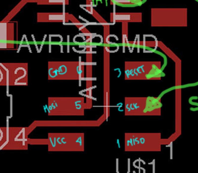
And upload the code!! Here was the critical point, I couldn't upload the program :S I received this message as you can see in the pictures: It looks that it happened not only to me but also to my Fab Academy classmates. After one day trying to find the errors in the components resistors and also trying to see if something was wrong in the connections, Tobias Pope, my classmate from Fab Lab Bottrop, helped me to verify the eagle file, and we found a fatal error, I erased a connection in the board !
I erased a connection in the board !
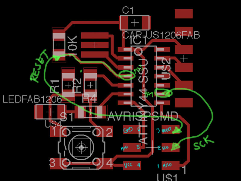
After soldering a provisional wire I did the test with the Blink. After this, I tried to program my board with the C programming using the makefile. I could program it with the “Button” and Blink function based on the sketch from my colleague Karsten Nebe. I test the board sending the data with the keyboard!
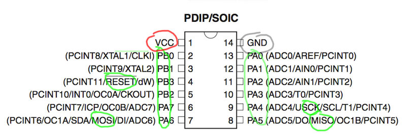
In the following picture you can see the pins distribution of the Attiny
The Attiny is a optimal microcontroller for running simple Programs
PINS
After soldering a provisional wire I did the test with the Blink. After this, I tried to program my board with the C programming using the makefile. I could program it with the “Button” and Blink function based on the sketch from my colleague Karsten Nebe. also the following code, is made in arduino Software .