
Week 15: Networks - The Fab-Pic CAN
The task was to build a network out of 2 or more controllers, connected
by some kind of data-bus.
Neils has not presented the CAN-Bus, so my idea was to build up a network with
two Fab-Pics
The CAN-Bus is a differential-serial-data-bus developed by Bosch in the late
80ies. Due to the differential-style it is very robust against EMV, also with longer cable-connections.
So it is build into every modern car to let the ECMs talk to each other, and also on some newer
(big) machines the CAN-Bus is used very often.
Some Facts about the CAN-Bus: The bus has no master, every client in the network can
send its data at any time.
Every client has a hard-coded identifier. The developer can choose how to deal with this identifiers.
In a car the most identifiers are used for a special sensor-value. For example the engine-temp has a
identifier instead of the ECM connected to the sensor.
The identifier can be changed on every sent paket. This way a single client can send out pakets
with different identifiers.
The arbitrary on the bus is made by the identfier of the paket (low indentifier = high priority).
Some PICs have a CAN-Modul build in (the ones with a 8 or a 80 at the end of the type-number).
If there is no build in you need an external CAN-IC (for example a mcp2551).
In every case you need a CAN-Tranciever-IC. This IC makes the RX and TX-lines to a differential signal (for example MCP2515).
On the bus-lines all clients are parralel-connected. The bus-lines itself are terminated with a 120 Ohm resistor on each end (2).
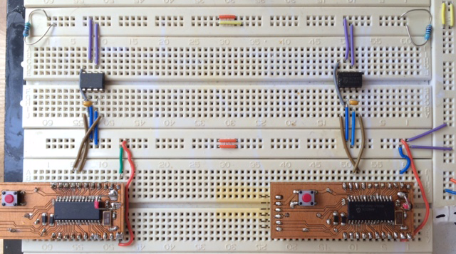
Due to the fact that the Fab-Pic is bread-board-compatible i made my circuit on a bread-board. For the CAN-trancievers
i choosed 2 old ones i had from an old project: the PCA82C250 from Philips, now NXP. It is pin-compatible to the modern types but not as fast. No Problem for this task...
You can find the Datasheet here!
The pinning is quite forward, the tranciever needs Vcc and GND, i´ve put a 100n-capacitor between them to make a more stable
voltage.
Rs is connected to GND. On this pin you can tweak the speed, no need for me.
CANH and CANL are the two can-bus-lines. All devices in the network are connected parralel to these lines, the lines itself are terminated
by a 120Ohm resistor on both ends.
TXD is connected to the CANTX Pin of the Fab-Pic (RB2)
RXD is connected to the CANRX Pin (RB3)
Don´t wonder about the tx-tx rx-rx connection. When i started with the trancievers i tought the connection has to be between rx-tx and tx-rx as usual.
Not on these ICs... (Page 9 of the Datasheet) Hard to find if you not read exactly ;)
The network looks like this:
Let´s program this network...
I´ve written two little programs, only difference is the ID of the send/received packages.
The goal: If you push the onboard-button on the left Fab-Pic the onboard-led on the right Fab-Pic should glow.
And vice versa.
We will use a microchip-provided lib for the CAN-Bus. It is a little bit hard to find, you need to
install an old app called "Application Maestro". Or you download the zip on the bottom of this page..
First we have to define a struct for the can-subroutines:
struct CANMessage RX_Message, TX_Message; //Declare one message structure for transmission and one for reception
Pretty selfexplaining i think.
Next we init the CAN-Controller inside the Pic by
CANInit();
If we want to send a message we have to setup the TX-Struct and send the message out:
TX_Message.Address = 0x1;  //Set the address to My identifier

TX_Message.Ext = 0;		   //If the identifier is standard, clear the Ext flag

TX_Message.NoOfBytes = 1;  //Set number of bytes to send

TX_Message.Data[0] = 1;    //Fill the data byte(s)

TX_Message.Remote = 0;	   //clear the remote flag

TX_Message.Priority = 0;   //Internal CAN module priority 0-> least priority, 3-> most priority

CANPut(TX_Message);		   //Put the message in the FIFO
Lets write the code for sending our button:
  TX_Message.Address = 0x1;  //Set the address to My identifier

  TX_Message.Ext = 0;		   //If the identifier is standard, clear the Ext flag

  TX_Message.NoOfBytes = 1;  //Set number of bytes to send

  TX_Message.Remote = 0;	   //clear the remote flag

  TX_Message.Priority = 0;   //Internal CAN module priority 0-> least priority, 3-> most priority

  while(1){

       TX_Message.Data[0] = !onboard_button;    //Fill the data byte(s)

       CANPut(TX_Message);		   //Put the message in the FIFO

       delay_one_second();        //Make a one-second-bio-break

  }
In this loop we check if the button is pressed, and send out a package on the bus with address 1 and the status of the button in the first data byte.
We also want to receive something from the bus, the status from the other button.
The code is also very straight forward:
if (CANRXMessageIsPending()) RX_Message=CANGet();
This subroutine checks if there is a received message in the buffer and save it to our RX-struct.
To let the LED shine we program:
if (CANRXMessageIsPending()) RX_Message=CANGet();

        if (RX_Message.Address == 2)  //is the sender the second fab-pic?

         {

             onboard_led = RX_Message.Data[0];

         }
And once all-together:
  TX_Message.Address = 0x1;  //Set the address to My identifier

  TX_Message.Ext = 0;		   //If the identifier is standard, clear the Ext flag

 	TX_Message.NoOfBytes = 1;  //Set number of bytes to send

 	TX_Message.Remote = 0;	   //clear the remote flag

 	TX_Message.Priority = 0;   //Internal CAN module priority 0-> least priority, 3-> most priority

   while(1){

          TX_Message.Data[0] = !onboard_button;    //Fill the data byte(s)

          CANPut(TX_Message);		   //Put the message in the FIFO

          delay_one_second();        //Make a one-second-bio-break

          if (CANRXMessageIsPending())

               {

               RX_Message=CANGet();

               if (RX_Message.Address == 2)  //is the sender the second fab-pic?

                    {

                     onboard_led = RX_Message.Data[0];

                    }

               }

          }
As said, the only thing that has to be changed on the second Fab-Pic is the TX_Message.Address and the RX_Message.Address...
I´ve programmed the two pics and everything works perfectly!
UPDATE:
Argh! I forgot to make a video from the working network...
No problem, put the program in and make it now.
Good idea...
The bad news: Last week i had a workshop in our FabLab with 20 students. Before i had 22 working Fab-Pics.
Now i have two destroyed Fab-Pics, 19 lost Fab-Pics and only the original first prototype is left.
How to make a network with one controller? Very lonely...
With the next bunch of Fab-Pics (boards are orderd by PCB-Pool) i will make a new video, but this will after the docu-deadline :(
Hope this will not be a big problem...
So long, feel free to download the souce and build your own CAN-Network!
DOWNLOAD
Have fun!