Welcome to week 6:
Now we learn how desing our own circuits, this week we learn how to create a board almost cero. That mean that we will design the circuit putting together different parts like the Integrated circuit, the resistors, clock, capacitors, etc,etc. The assigment this week is modify the Board we do in week 4 adding a button and a LED at least, however because in my robot project I will need a board based in arduino for the motor and another for the sensors I will do an Arduino board instead of the board of week 4.
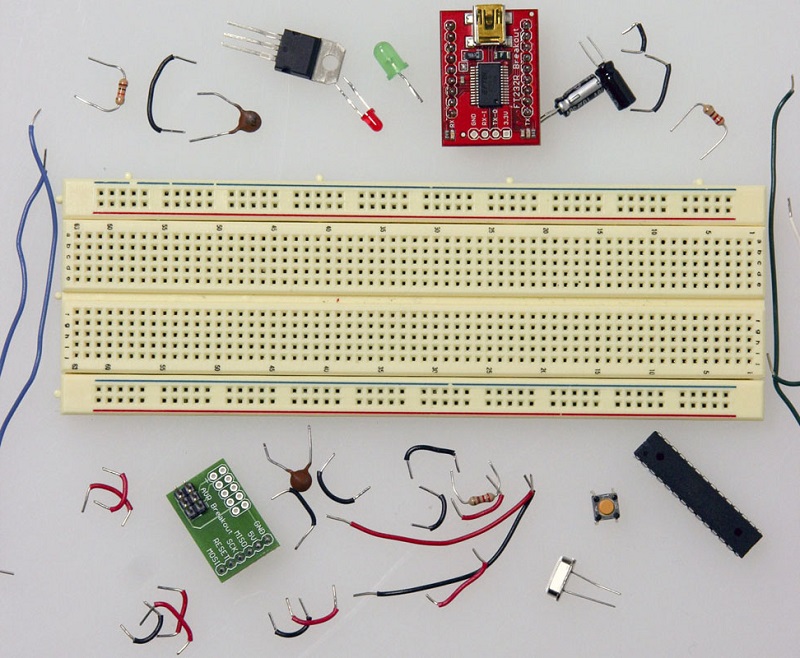
In general there is two way of do it, the simplest and easy is with a Breadboard and put the components by pressure, like this:
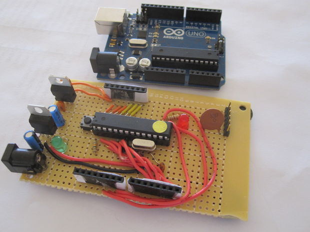
And then, you get something like this:
This is the easy way to experiment and learn, but we need something more permanent. The other way is made an PCB and solder the components, this is good for final products, we will do this way with a PCB machined in a MODELA MDX 20, the design to be machined will be do it with Eagle software and exported to PNG imagen to the Modela. In Fab Academy there is a model call Fabduino:
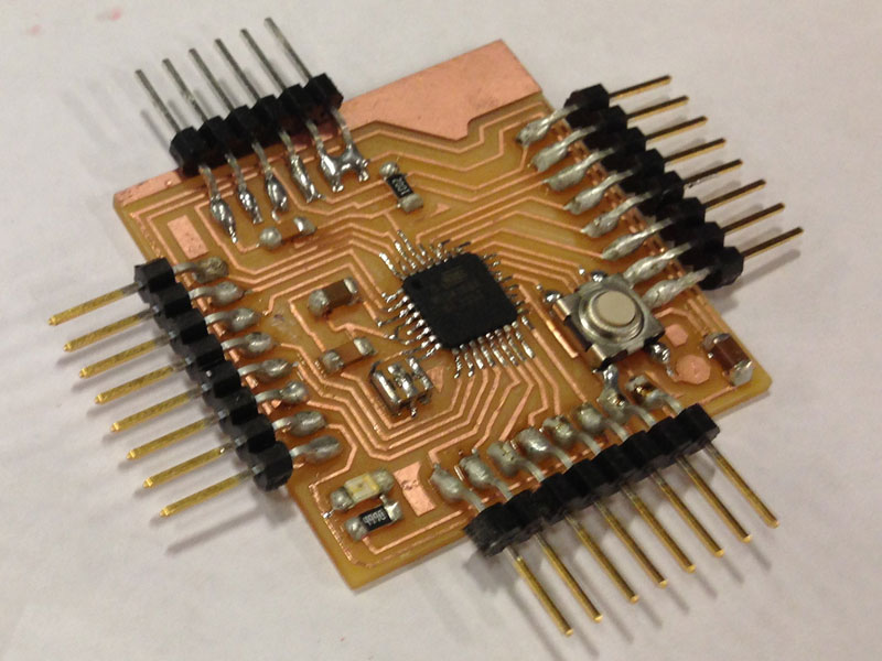
I will do a board simmilar to it, but my own desing. In order to do it I will follow this steps:
1.- Understand what is Arduino and Atmel chip, how they work and how program it. This is a critical part because in week 4 we create an board but just following instruction, not understanding everything, because the focus of week 4 was soldering and set up the board
2.- Define specs of the board and Create a part list and initial sketch
3.- Put the element into EAGLE CAD software and learn how to use this software to create the PCB design
4.- Print in the MODELA the PCB and solder the components
5.- Test the board and flash it in order that the IC inside the Board behave as an arduino
6.- Program something, maybe the Blink Link in the arduino tutorials
Lets start...
PART 1: Understandig arduino board
This is the research part, we need to understand the chip inside the Arduino, and the design of the board inself, we need to read a lot but affortunally they are a lot of resources in the web about it, my recommendations are:First go to the source: this link send you to Arduino official page and show the specs of the Arduino UNO, the current model. There we see the specs and Chip usde, the ATMEGA 328, but better than, because is an open source product, you find the design of the board on DXF (ready to cut), an PDF with the whole circuit, and an Eagle file ready to machine the board.We dont use this file to made our board, but reading the circuit design we can learn a lot.When you read the info about the Arduino Board, you find an interesting thing:
- If you remember week 4, we create and
board wiith and ATtiny integrated circuit and later we program this
board with another board with the same chip. In the design of Arduino
they put TWO Integrated circuit inside, not just one. The main is the
ATMega 328, which is the main chip, and another Atmega 16u2 (an smaller
cousin) inside to use for programming and communication by the USB. So
inside an Arduino is like two boards, the main board and the
programmer. Clever design, but we will omite the secondary IC chips and
will program the board by the serial terminal.
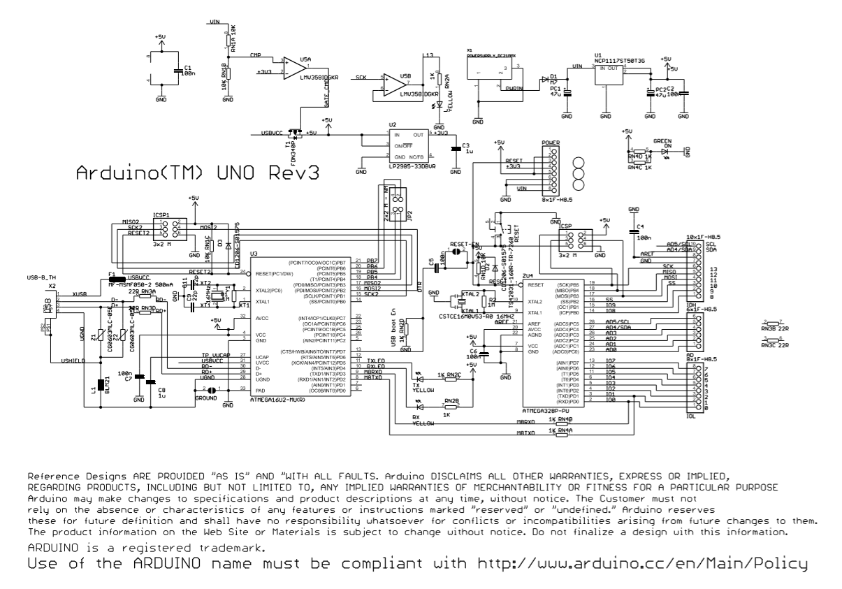
After review the design of the board, I find that the board can be divided in four parts: The components related to the voltaje regulations, the components related to the clock, the components realted to communication by USB (here is the secondary chip) and the components for the input and output pins.
- Our design will be simplified: a simplified version for the voltaje regulation, for the clock, and the IO pins, we ommit the secundary IC for communications, but use instead and USB to serial interface
Another good resource to understand arduino board is wikipedia, in this article you will find a lot of info of arduino and the chip inself
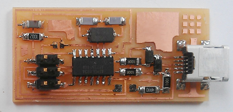
Finally, to understand how it work, and how program it with avr-dude I find this great tutorial from ladyada, thanks to it I finally undestand the command to program the Board. I will use to program my Arduino the board that we create in Week4.
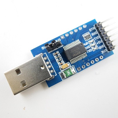
Or even use a purchased programmer that do exactly the same, like this
Other interesting resources to this project are:
http://vonkonow.com/wordpress/2012/10/nanino-the-diy-friendly-arduino/
http://www.instructables.com/id/How-to-make-an-Arduino-from-scratch/
http://diyhacking.com/make-arduino-board-and-bootload/
http://www.makeuseof.com/tag/dont-spend-money-on-an-arduino-build-your-own-for-much-less/
http://www.instructables.com/id/How-to-make-your-own-Arduino-board/?ALLSTEPS
http://www.instructables.com/id/How-to-make-an-Arduino-from-scratch/
http://diyhacking.com/make-arduino-board-and-bootload/
http://www.makeuseof.com/tag/dont-spend-money-on-an-arduino-build-your-own-for-much-less/
http://www.instructables.com/id/How-to-make-your-own-Arduino-board/?ALLSTEPS
PART 2: Define Specs and Part List
The best way to start with it is go to the official info of Arduino, there are a great tutorial to create a arduino in a breadboard, we use this sequence to build, but instead of put in the parts in a breadboard, we put the parts into the EAGLE program and do the PCB design.
First, we need to take note that in most tutorial they use a ATMEGA chip in a large version call ATMEGA 328P-PU, like this
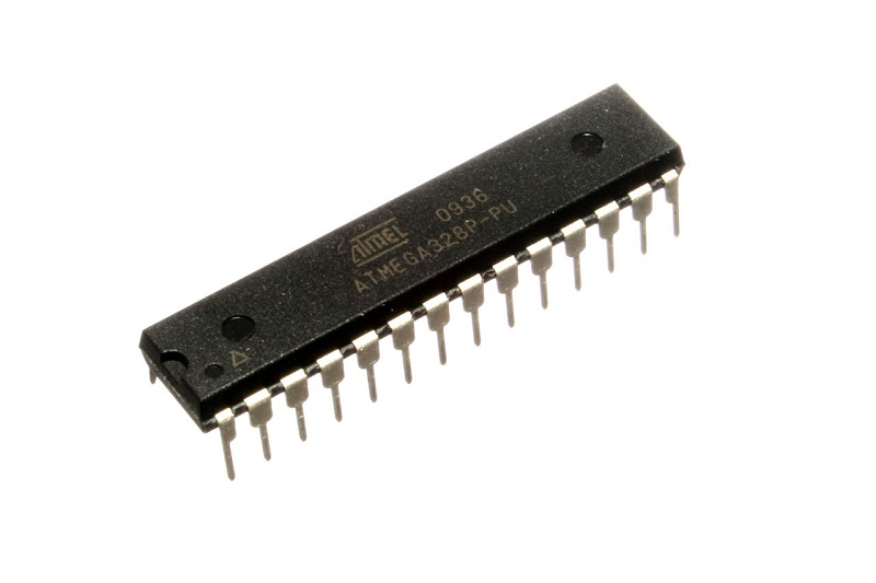
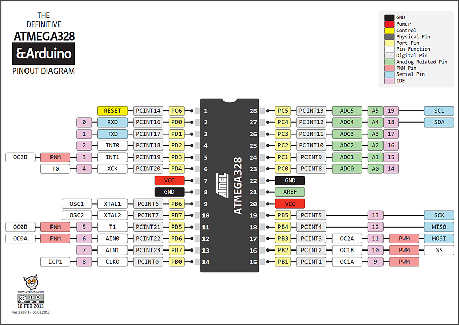
This is a, large circuit almost 4cm large by 1cm wide. The pinouts are like this:
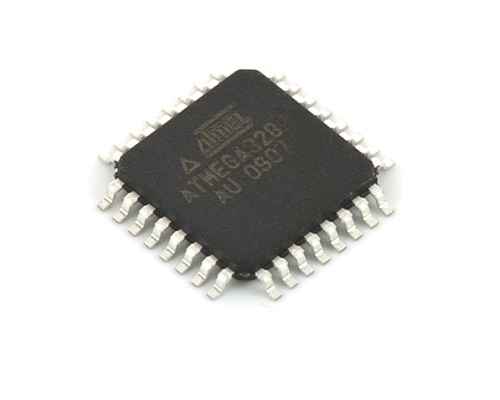
However in the FabLab we have a smaller version ATMEGA 328P-AU, it is just the same chip, but in a different package. The one we have in the Fab is the smaller version, just 1c, x 1cm.

sa