

so i decided to do the step response. i milled out the board as-is to try it out and then i will add some extra component, perhaps lights to indicate change.


i had a few pieces of left over wood from the make it big project and i covered them with copper foil (again reused from a failed attempt to use the vynil cutter to make a board a few weeks ago.)
i had to look carefully at the board and diagram to see which wires from the 4-pin header to connect (with key facing away from you from left to right) start back front back front.
also noticing the way this board is drawn has crossing wires which i have never seen before, but they all go to ground so it makes sense in my mind.
connected to fab isp... checked back at embedded programming to see protocol for programming… completed "make" but not "program usbtiny"
###
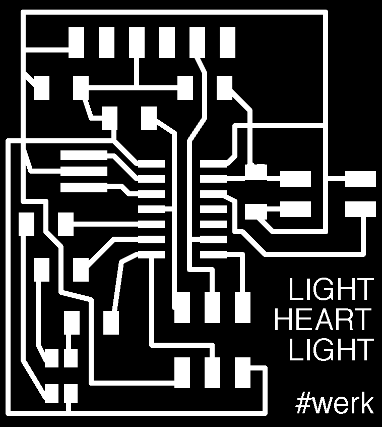
re-doing board and deciding to add a crystal so as to not have to worry about baud rate, with a attiny44 and rbg. ligt to show intensity of change it is reading in from environment... just realized i need 3 resistors with this light meaning 3 pins...


decided to print out board images of output board rbg; hello echo (with crystal), and the step response board and physically cut and paste components and draw route with a marker before going into eagle and creating the schematic and board design b/c the workflow in eagle is kind of rigid and can be frustrating to move items around once started… i've got the visual of how it can work and the logic of the electrical circuit and so now its much easier for me to lay out the schematic in eagle. i used the data sheets for both the ATtiny44 and ATtiny45 to see what functions and capabilities the pins have, and what decided from there how to connect. i made sure that all of the pins that connect to the LEDs on the light had PWM.

got the layout... making sure that the connections to hardware and set up are alike, and switching pin numbers. referred to the data sheets to see which pins were more likely to drive the light, as well as other dedicated functions. i kept referring to the pinout diagrams of ATTINY45 and ATTINY44here are my additions and changes:
changed::
FTDI Rx- old: PB2 new: PA4
microchip- old: ATTINY45 new: ATTINY44
4-pin header Pin 1 (rx) old: PB3 new: PA0
4-pin header Pin 4 (tx) old: PB4 new: PA1
added::
Xtal to PB0 and PB1
1K resistor to PB2
1K resistor to PA7
499K resistor to PA6
connected to RBG LED
i have made the best board in eagle that i have ever made and of course i hit a glitch... as i go back to assign values to my resistors... i accidentally undid something making R2 remain untouchable outside the work area in the board view... i cannot drag it in, i will manually add pads next to the 4-pin header in photoshop.

click here for Eagle schematic file
click here for Eagle board file
click here for png file
workflow:
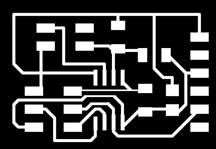
i went from collaged paper to Eagle to Fabmodules to the Roland Modela. *yikes* after milling a beautiful board i accidentally sliced through the outermost trace when cutting out the board! i was a bit too close and so i had to mill out another. an important lesson when designing a board- 1. either leave more black space around traces or make the interior cutout path one millimeter larger all the way around... in my layout i had to make two jumps... i chose to mill the traces (with wires that would cause a short intersecting) and then afterwards cut the traces with an xacto knife and then reconnect using 0 ohm resistors. i successfully stuffed and tested the board with the multimeter.


i then went back to the original board, attached it to the hearts, and programmed it using the given c code and python programs, and it worked. i am in the process of changing the code to include the added function of the LED on my board.
click here for my c code.
### REVISIT###
i resigned the original board with a ATTiny45 after many weeks of wanting to make this work.

after milling and just before stuffing this back-to-basics board i realized a mistake in my wiring and a connection that should have been there was not, and so i soldered a bit of wire to connect the traces.


click here for Eagle schematic file.
click here for Eagle board file.
click here for png file.
click here for c code.
click here for the video.