presentation.png
Steven Fett
Fab Academy 2016
Final Presentation
Purpose and Function
Files, Tools, Images
Purpose and Function
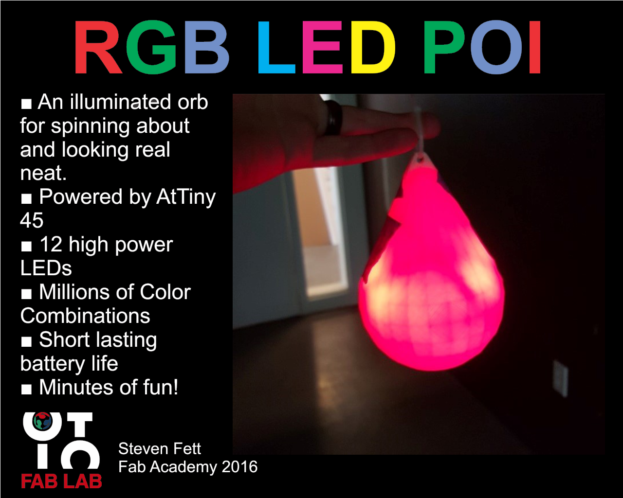
The LED Poi will be a pair of illuminated orbs meant to be spun by a rope or wire handle to be held by the hands of the user. The LED Poi will illuminate different colors patterns. The LED POI is made from 2 3D printed shells that houses the electronics and diffuses light cast through it.
Please See : Applications and Implications and Invention, Intellectual Property, And Business Models
Files, Tools, Images
Files Download
Files Directory
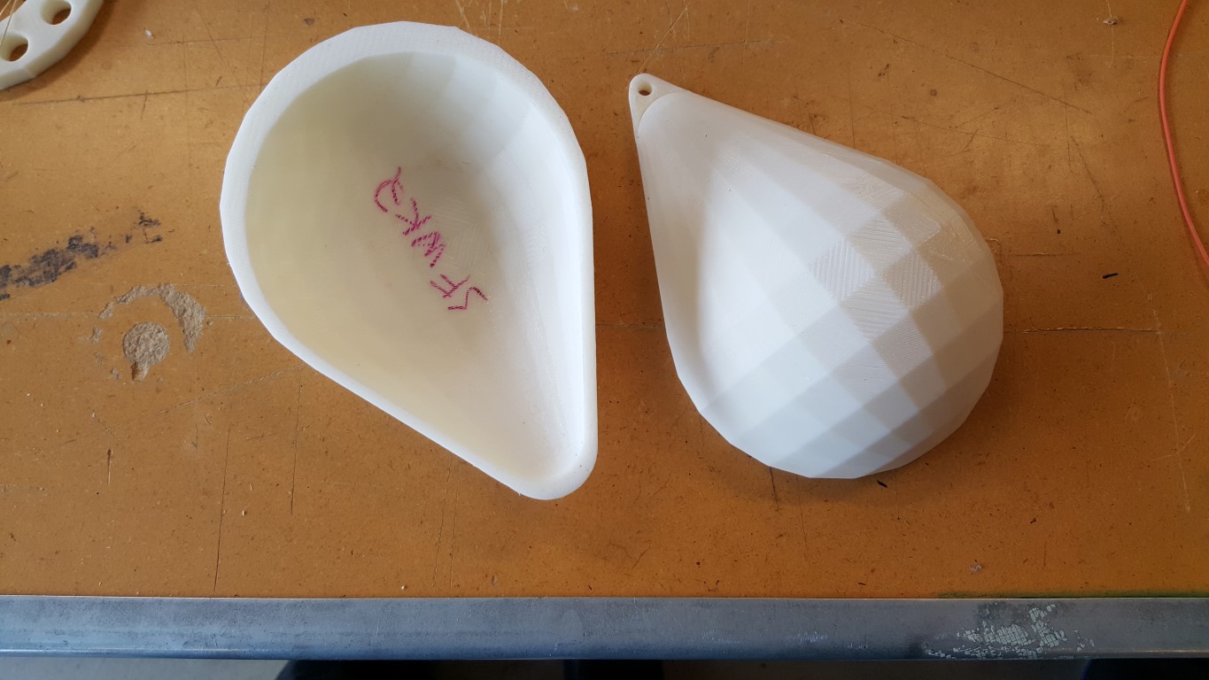
I began designing my final project during the second week of Fab Academy (WEEK 2)
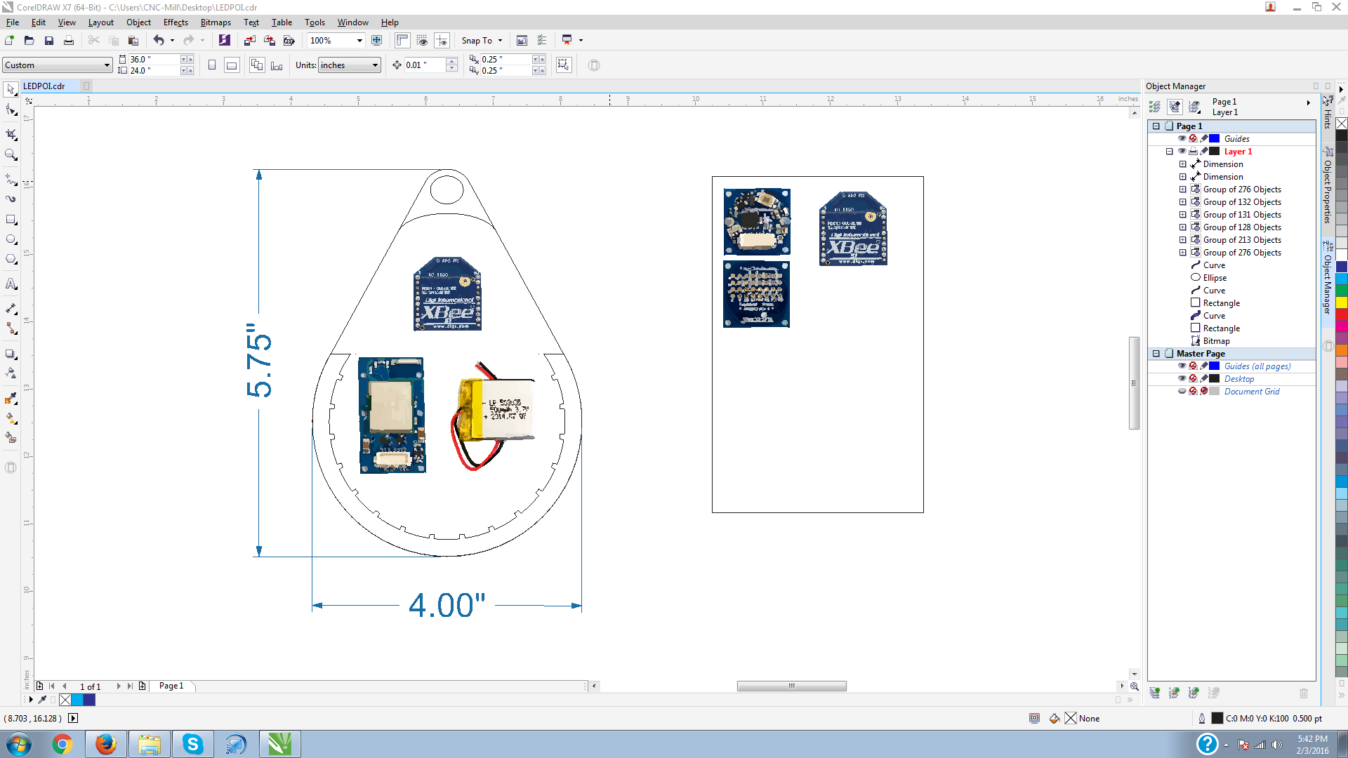
3D design of the project during the 5th week; 3D Scanning and Printing (WEEK5)
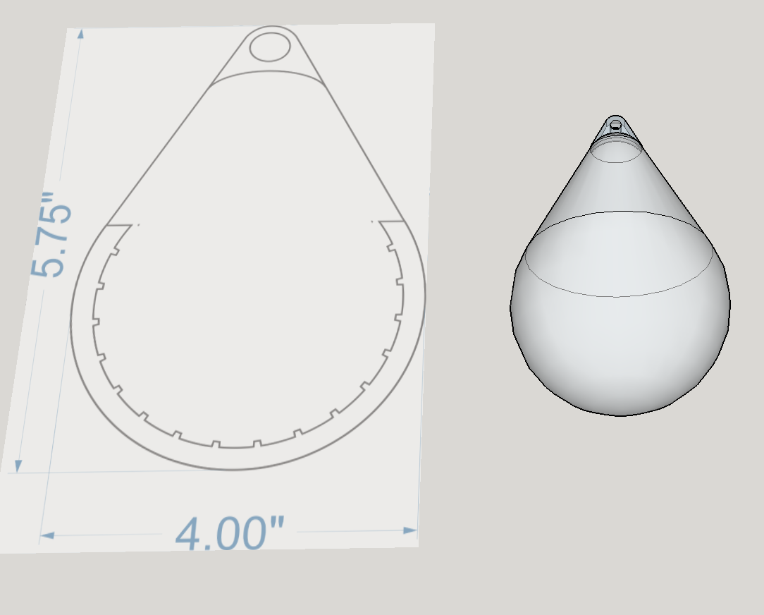
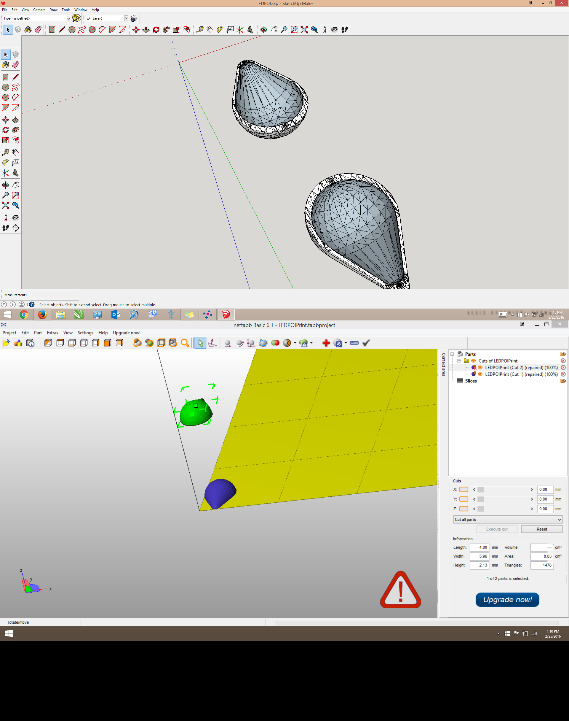
Using Sketchup and Netfabb to build the geometry. Printed on the Dimension 1250ES.
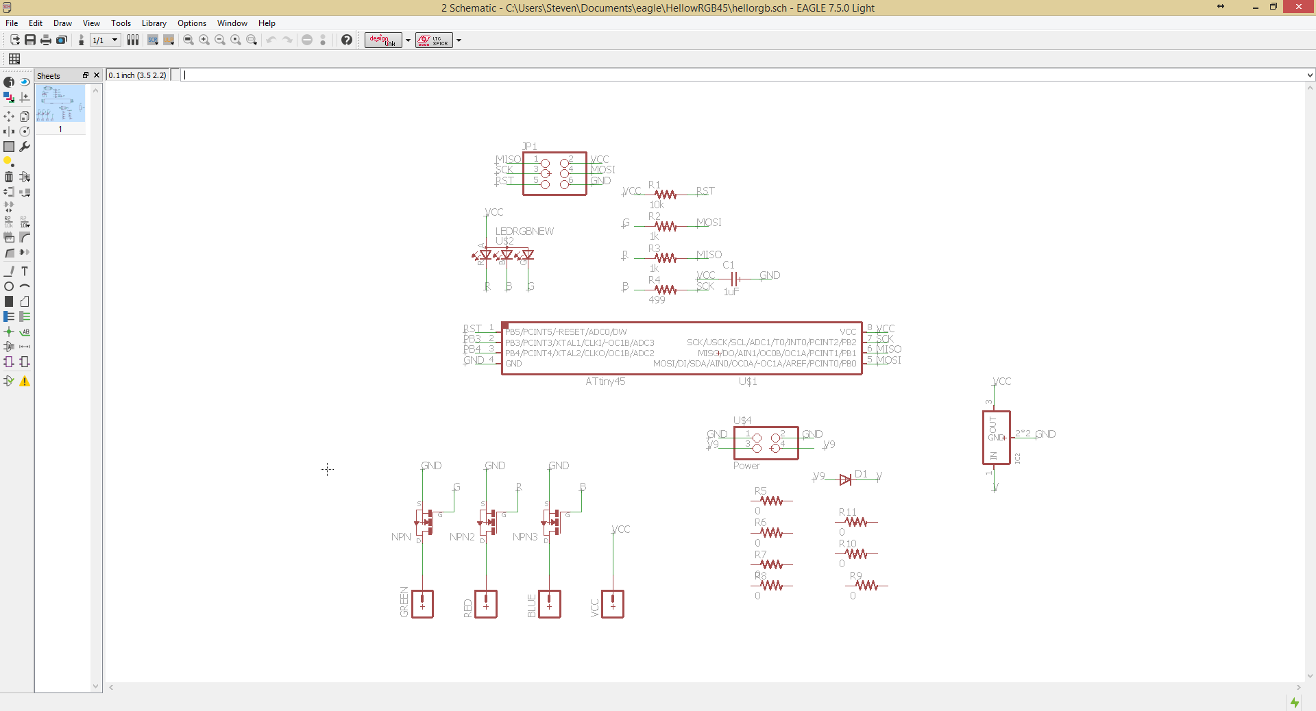
Electronics for the LED Poi are based off the Hello RGB Board (OutPut Devices) (Week 13)
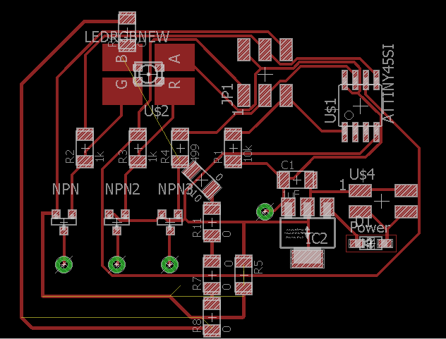
I added a schlotky diode, a larger voltage regulator, and NPN Mosfets to drive the LEDs
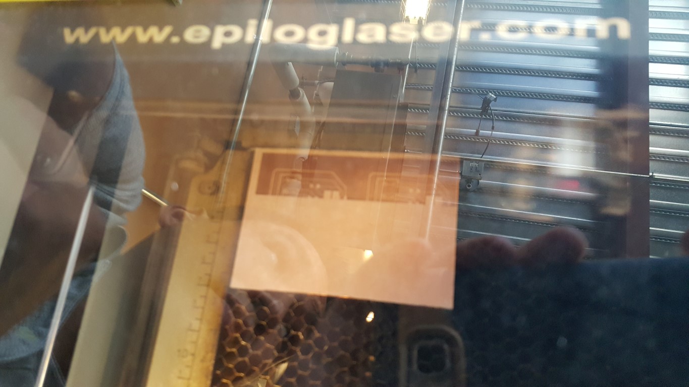
I attempted a different board cutting process for this board. Paper mask is applied to the board then rastered away.
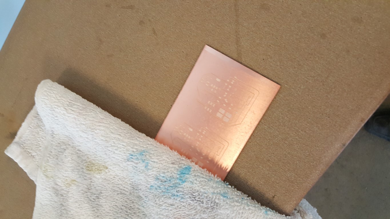
The mask is pressed using an iron, and left to soak in a hydrogen peroxide and vinegar bath for two hours.
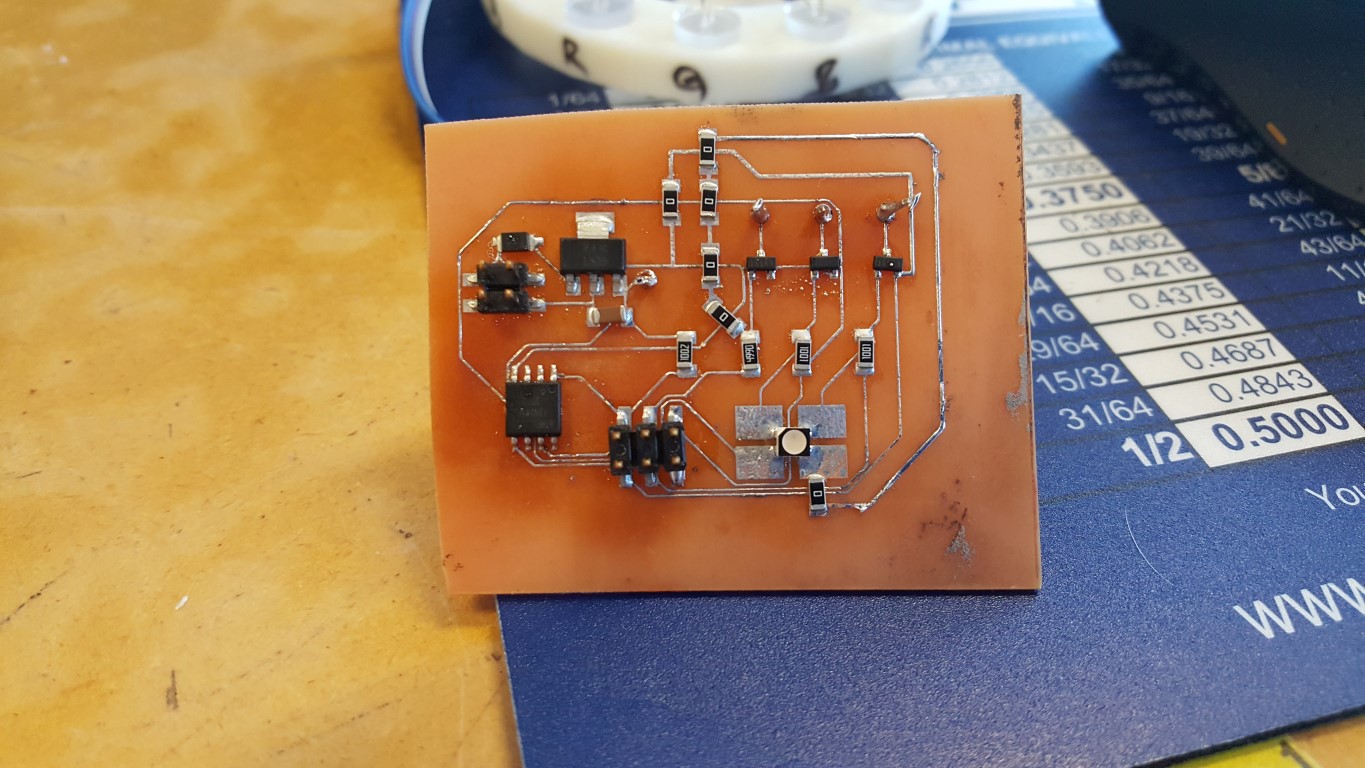
The traces are tinned to ensure conductivity, and components are added using reflow.
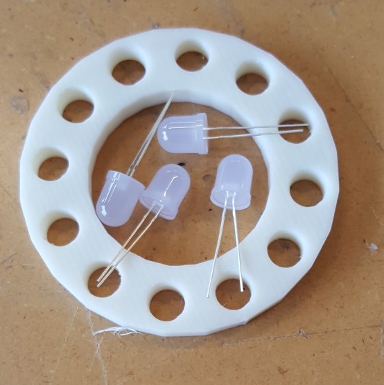
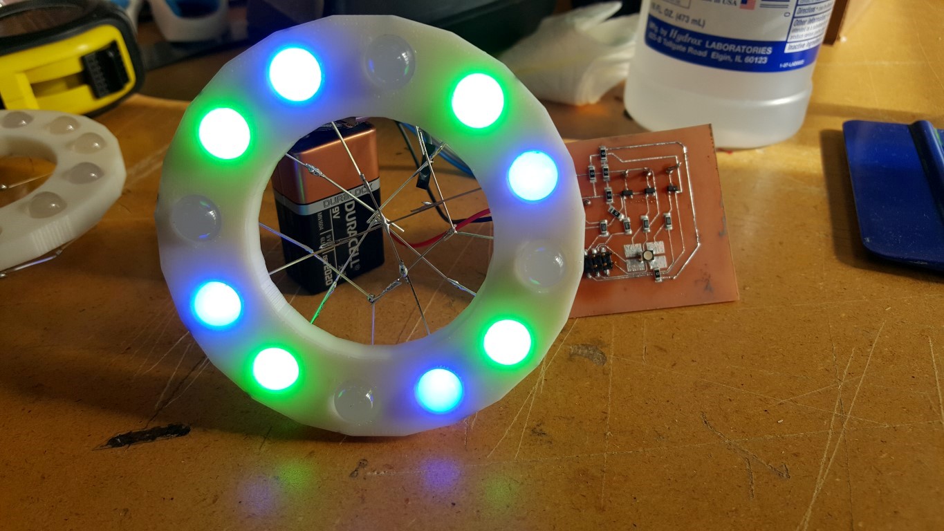
3D Printed ring housing using 10mm LEDs
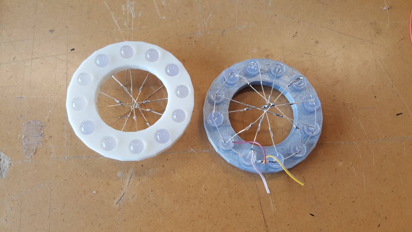
Two Diode rings assembled. One wired common anode, the other wired common cathode.
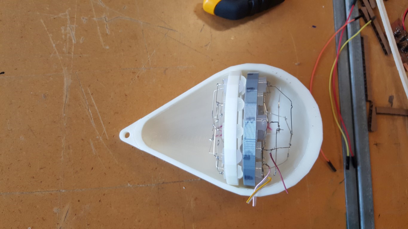
Both rings in the 3D printed shell.
I used the Hello RGB code from Neil Gershenfeld for my intial test. I still need to get learned up and write my own code.
//
//
// hello.RGB.45.c
//
// RGB LED software PWM hello-world
//
// Neil Gershenfeld
// 11/10/10
//
// (c) Massachusetts Institute of Technology 2010
// This work may be reproduced, modified, distributed,
// performed, and displayed for any purpose. Copyright is
// retained and must be preserved. The work is provided
// as is; no warranty is provided, and users accept all
// liability.
//#include <avr/io.h>
#include <util/delay.h>#define output(directions,pin) (directions |= pin) // set port direction for output
#define set(port,pin) (port |= pin) // set port pin
#define clear(port,pin) (port &= (~pin)) // clear port pin
#define pin_test(pins,pin) (pins & pin) // test for port pin
#define bit_test(byte,bit) (byte & (1 << bit)) // test for bit set
#define PWM_delay() _delay_us(25) // PWM delay#define led_port PORTB
#define led_direction DDRB
#define red (1 << PA2)
#define green (1 << PA3)
#define blue (1 << PA7)int main(void) {
//
// main
//
unsigned char count, pwm;
//
// set clock divider to /1
//
CLKPR = (1 << CLKPCE);
CLKPR = (0 << CLKPS3) | (0 << CLKPS2) | (0 << CLKPS1) | (0 << CLKPS0);
//
// initialize LED pins
//
set(led_port, red);
output(led_direction, red);
set(led_port, green);
output(led_direction, green);
set(led_port, blue);
output(led_direction, blue);
//
// main loop
//
while (1) {
//
// off -> red
//
for (count = 0; count < 255; ++count) {
clear(led_port,red);
for (pwm = count; pwm < 255; ++pwm)
PWM_delay();
set(led_port,red);
for (pwm = 0; pwm < count; ++pwm)
PWM_delay();
}
//
// red -> green
//
for (count = 0; count < 255; ++count) {
set(led_port,red);
clear(led_port,green);
for (pwm = count; pwm < 255; ++pwm)
PWM_delay();
clear(led_port,red);
set(led_port,green);
for (pwm = 0; pwm < count; ++pwm)
PWM_delay();
}
//
// green -> blue
//
for (count = 0; count < 255; ++count) {
set(led_port,green);
clear(led_port,blue);
for (pwm = count; pwm < 255; ++pwm)
PWM_delay();
clear(led_port,green);
set(led_port,blue);
for (pwm = 0; pwm < count; ++pwm)
PWM_delay();
}
//
// blue -> on
//
for (count = 0; count < 255; ++count) {
set(led_port,blue);
clear(led_port,green);
clear(led_port,red);
for (pwm = count; pwm < 255; ++pwm)
PWM_delay();
set(led_port,blue);
set(led_port,green);
set(led_port,red);
for (pwm = 0; pwm < count; ++pwm)
PWM_delay();
}//
// on -> off
//
for (count = 0; count < 255; ++count) {
set(led_port,blue);
set(led_port,green);
set(led_port,red);
for (pwm = count; pwm < 255; ++pwm)
PWM_delay();
clear(led_port,blue);
clear(led_port,green);
clear(led_port,red);
for (pwm = 0; pwm < count; ++pwm)
PWM_delay();
}
}
}
LED test
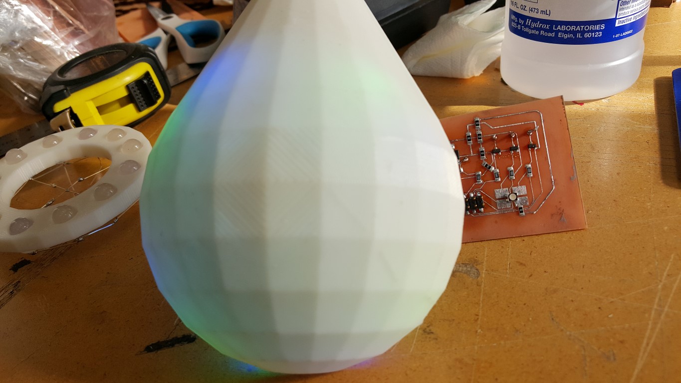
Light Diffusion Test
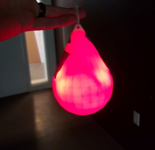
Works better in the dark.