Steven Fett
Fab Academy 2016
Output Devices
Add an output device to a microcontroller board you've designed and programme it to do something
Composites
Design and make a 3D mold (~ft2 /300mm²), and produce a fibre composite part in it
Output Devices
Output Devices.
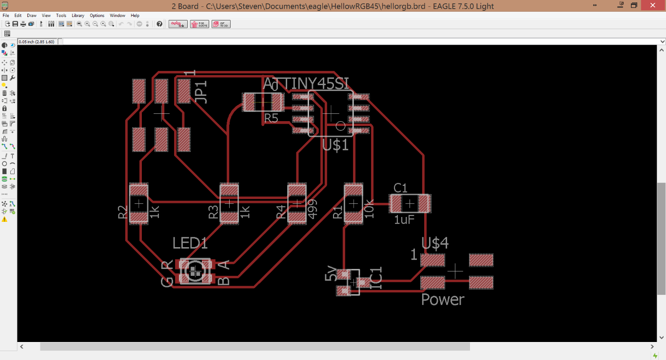
In order to try something would help me in creating my final project I decided to start with a pretty important component, the RGB LED. I figured the HelloRGB board would be the best place to start learning. After checking the component list I began building my sketch in EAGLE. After locating all of my components in the Fab Library, and also in my local inventory, time to layout the board. I found this to be a little tricky as it was diffacult for the Fab module to identify the difference between some of the traces. EAGLE would only let me tweak the placement of traces so much, so I did a teensy bit of component trimming in MSPaint to speed up my workflow.
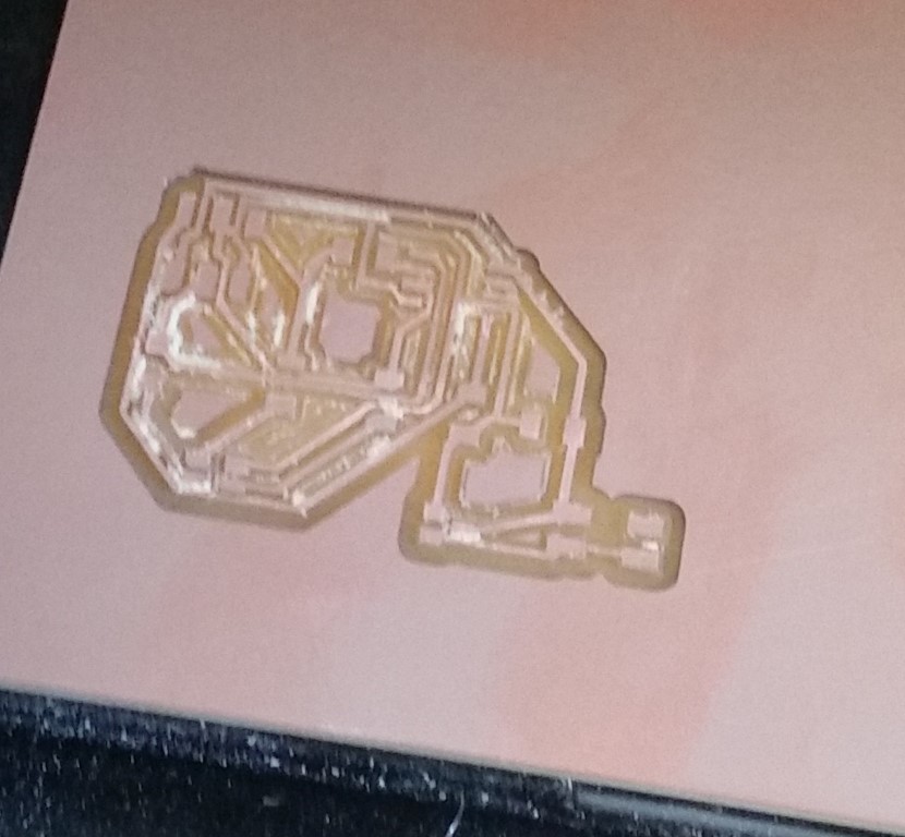
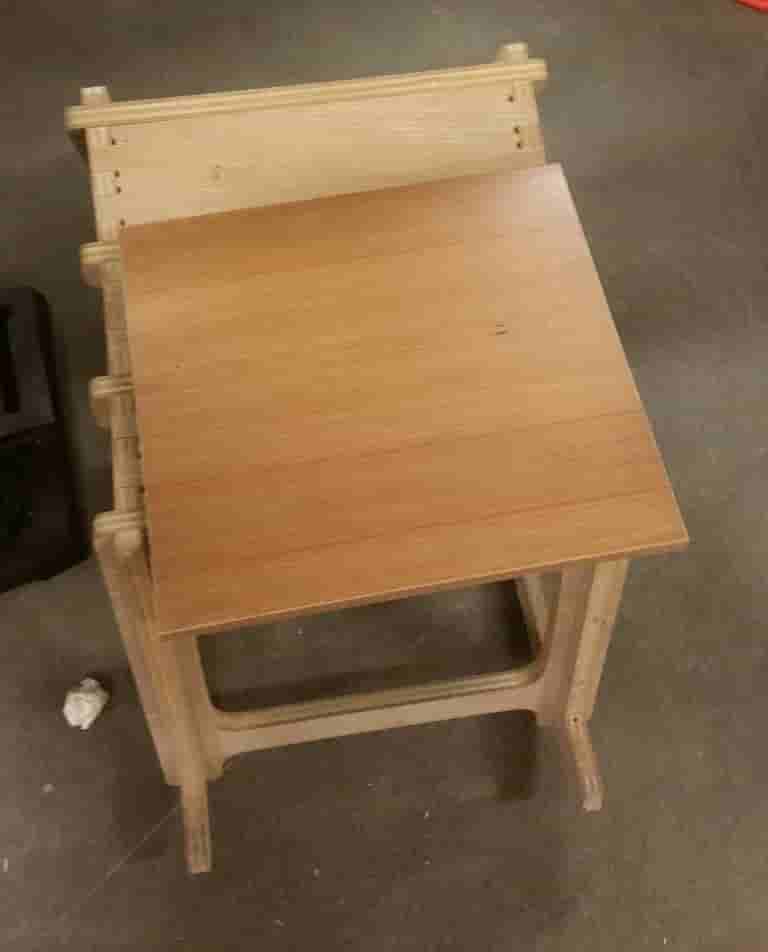
After double checking the expected size of my board in millimeters, and the interpretation of the FabModule. I began milling my board with the 1/64th inch bit. After cutting my board I noticed our new tube of "Lead Free" Solder didn't like to stick to my board. I used the Reflow station to cook my bare board a wee bit. This allowed the Solder to liquifiy onto the pads much more easily. I packed my board let the Reflow gun do its work.
I Soldered a 9Volt Battery lead onto my board and reinforced with a bit of hotglue. I enjoy a good old fashioned battery fire as much as the next yokel, but there's a time and a place for everything.
At this point I was most concerned with if i built the board correctly, so i laoded up the default HelloRGB code and pushed it to my board. Keeping in mind there is no resonator this time, so i set the clock to 8mhz internal.
Don't forget your bootloader.
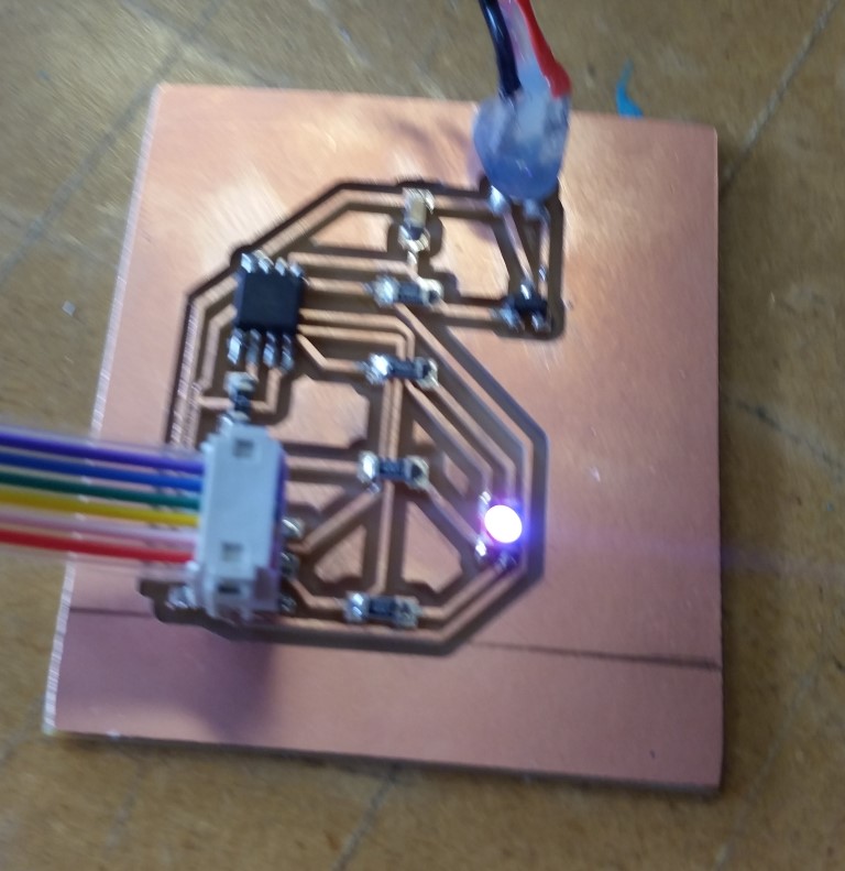
And... IT WORKS!
Phwew. Time to begin interpretting and writing code.
Composites
Composites
I decided to try and create a composite layered table tennis paddle. There has been some demand lately for custom paddles from co-workers in my company. I decided to create a 3-4 part component to be made in composite week.
Parts 1 and 2 are a composite layered paddle, while parts 3 and 4 are the "rubber" pads that are usually found on a paddle. My plan is to mill a negative half form of the paddle and cast with linen and smooth cast, the paddle area will be cast probably using Smoothon Silicone Rubber Mold.
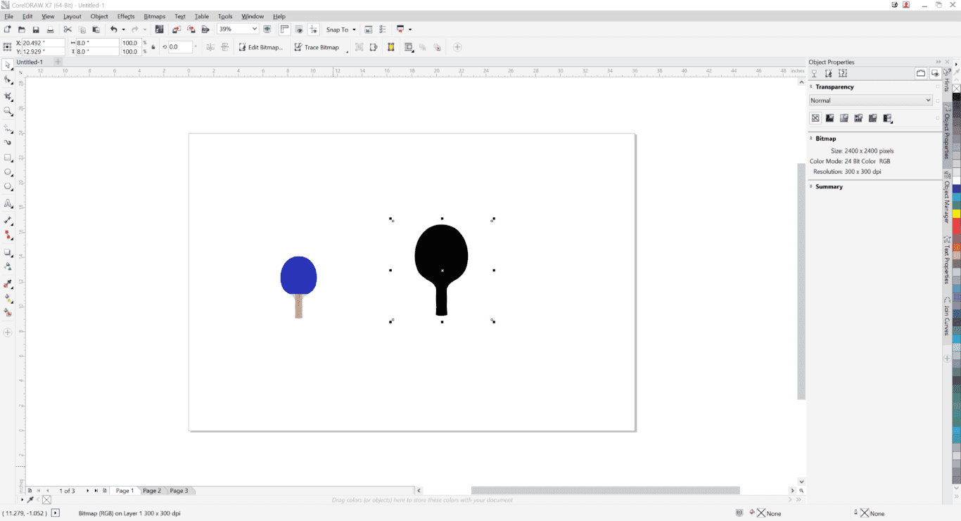
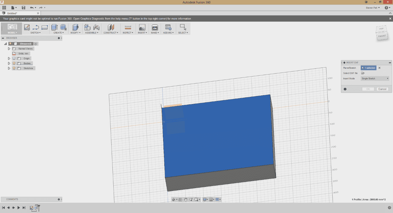
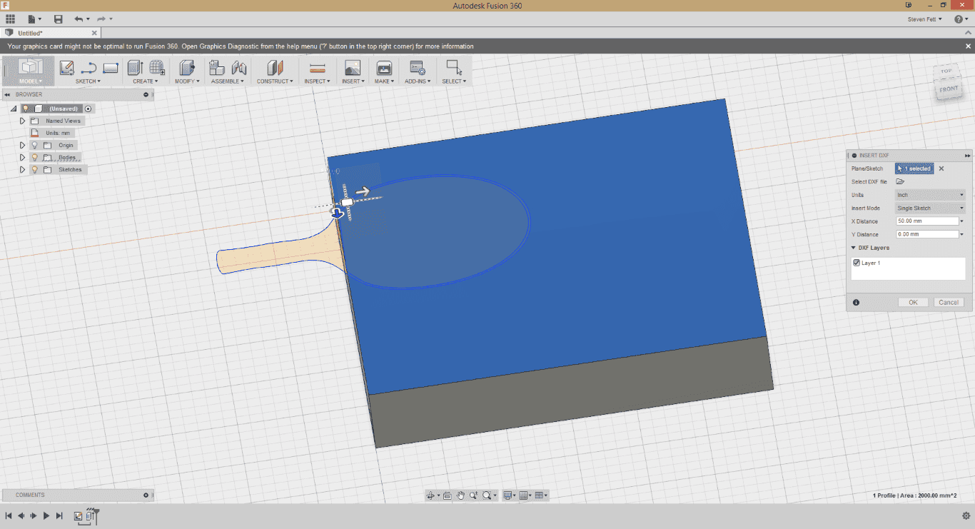
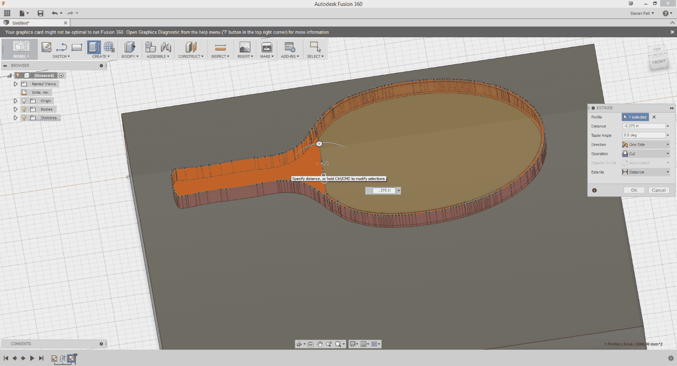
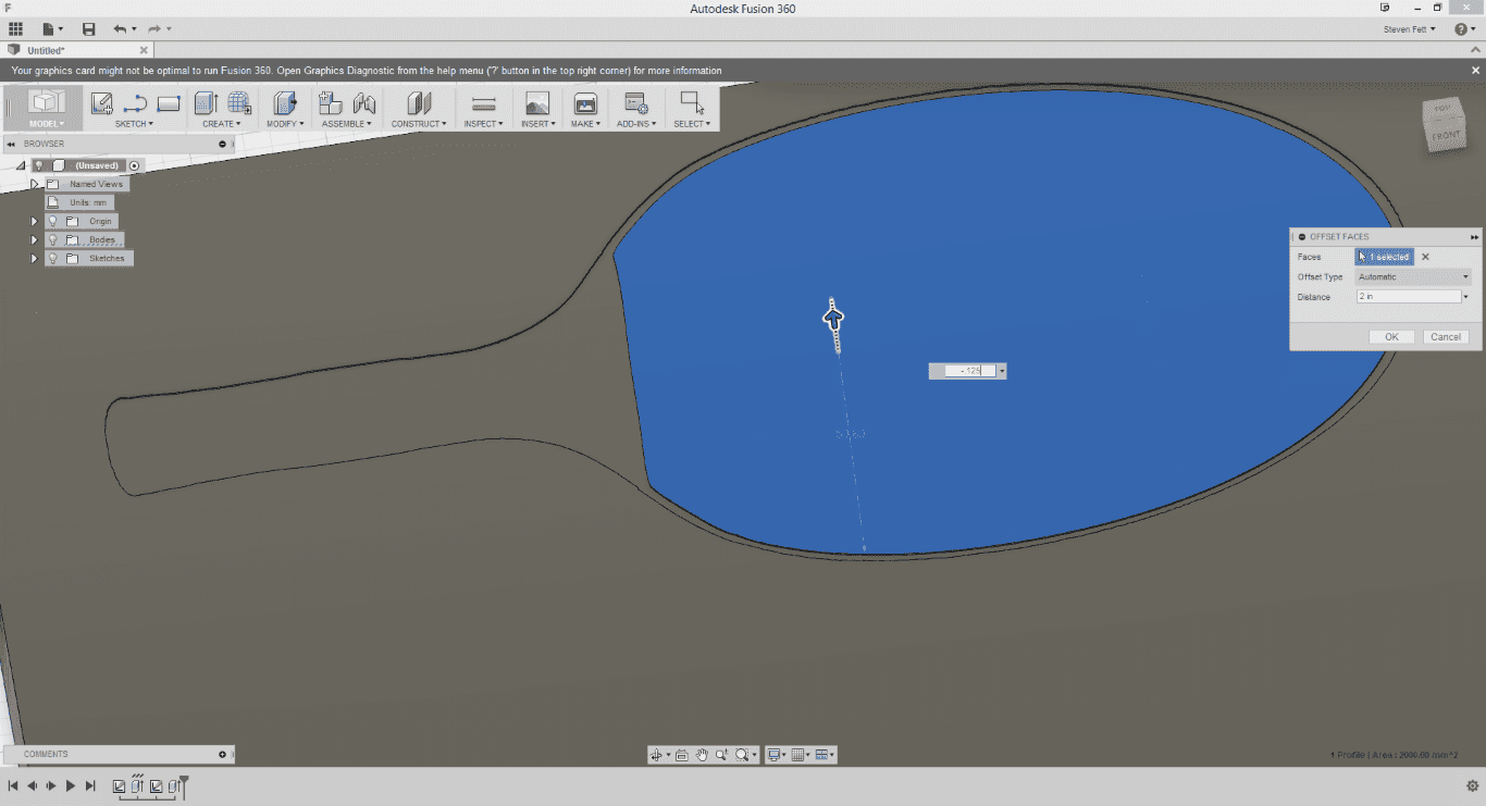
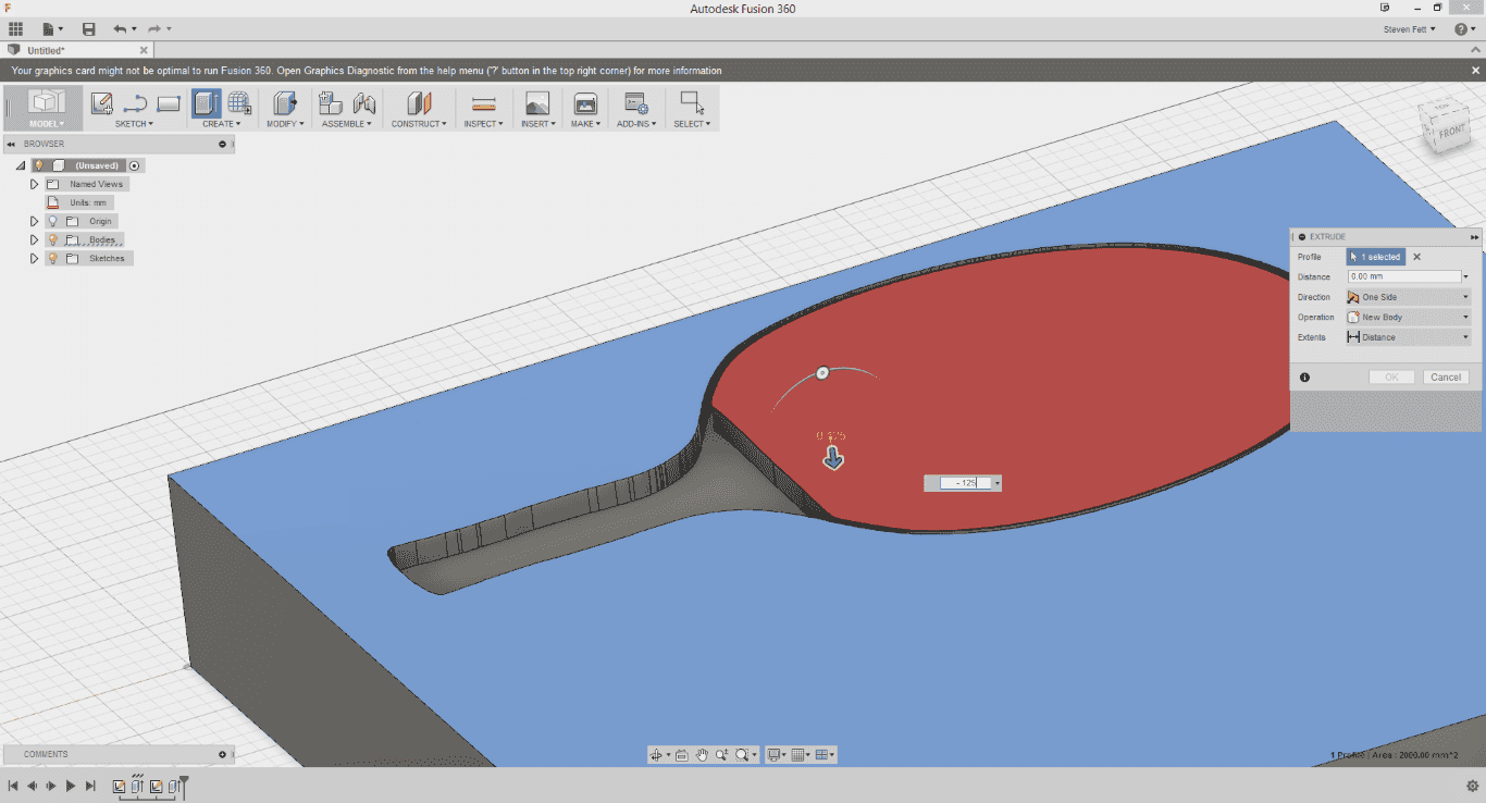
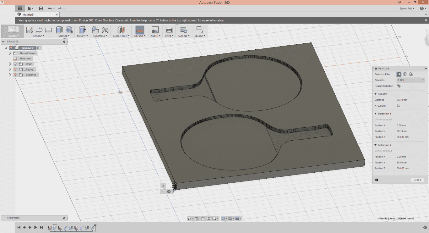
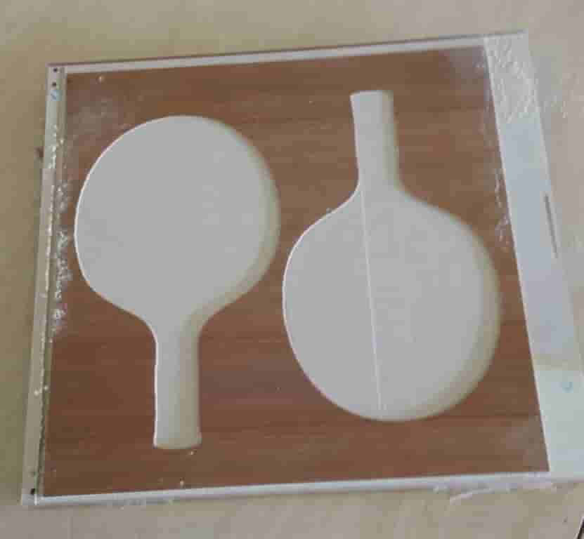
I used Fusion 360 to create a block the size of my material I will be milling. The material is a chunk of cabinet grade plywood, 13" by 14" by .632". After vector tracing a paddle I found on google images, I checked the dimensions with another google image search. Using Corel Draw I made a dxf of the paddle and pad outline. I then imported the dxf onto the surface of my material blank in Fusion 360. I extruded the paddle portion negative .25 inches, and the rubber pad negative .125 inches. This left me with a negative version of the form I was planning to make. I added a second mold form to my blank. This should give me two half paddles at .25 inches each, making one paddle that is .5 inches thick.
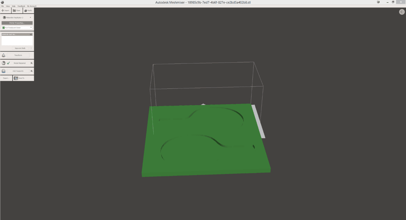
I created my tool paths in Aspire, using 3D rough cut, .125 inch spiral single flute upcut bit. I ran the job with .062 inch cut depth at 70 inches/minute, %20 tool overlap. Slow and Steady with high tool rpm (in my experience) gives the best finish without material blowout.