Final Project
This is a summary of the final achievements. I skipped describing obstacles as in Process, just discussing the elements which where implemented.
Menu
- The frame
- The drive module
- The camera module
- The electronics
- Programming the microcontroller
- Application & interfacing
- Downloads
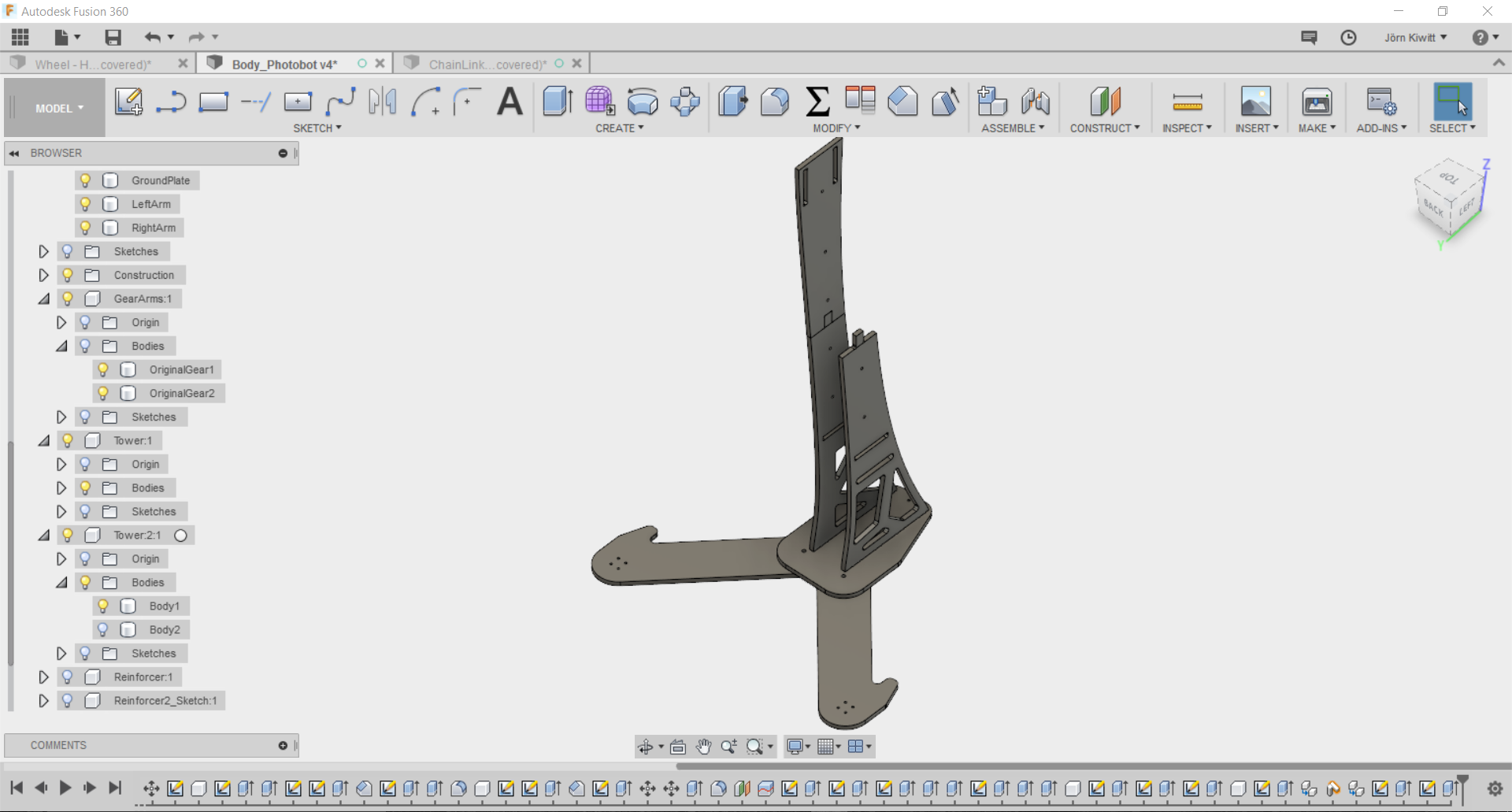
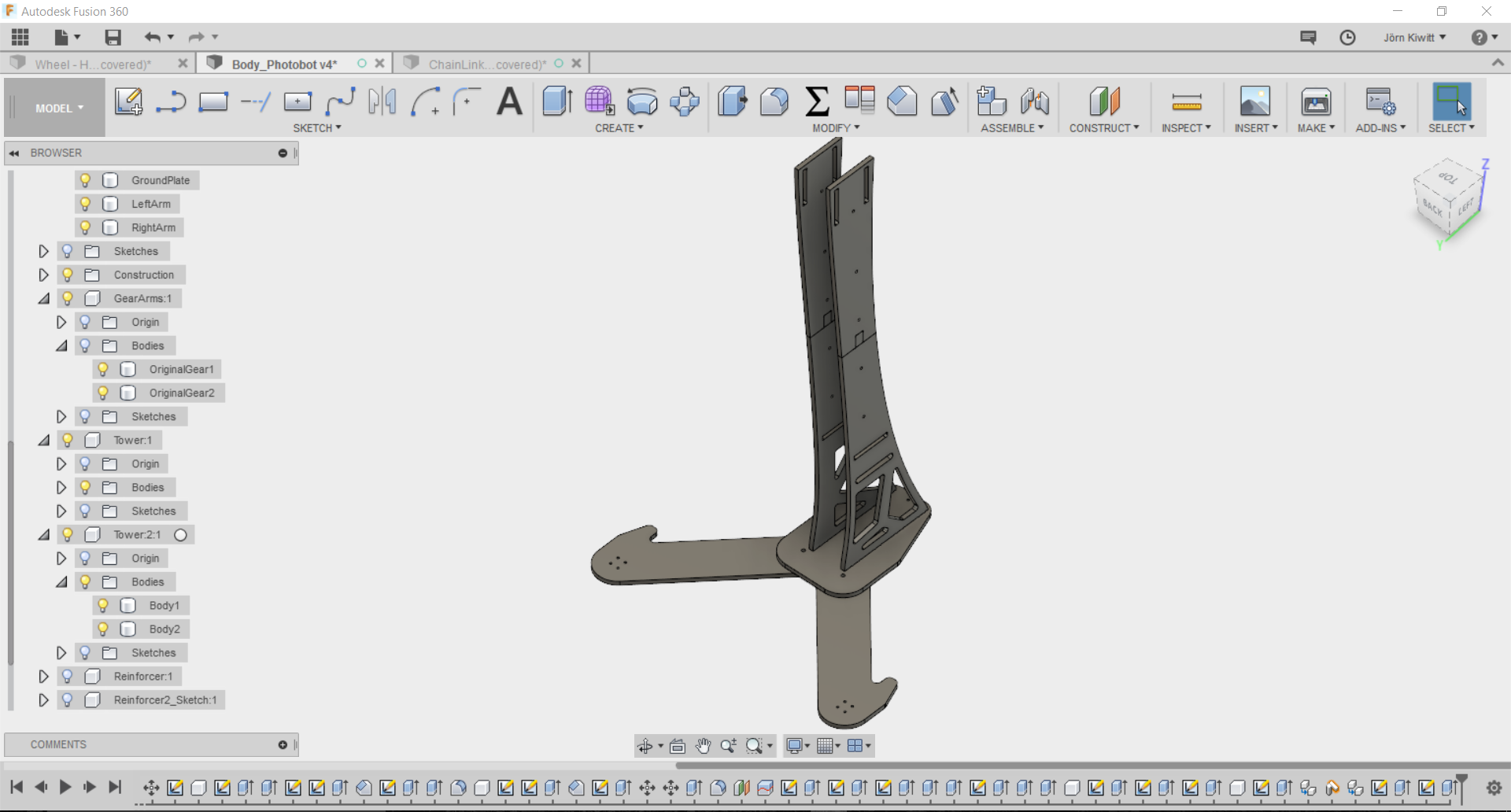
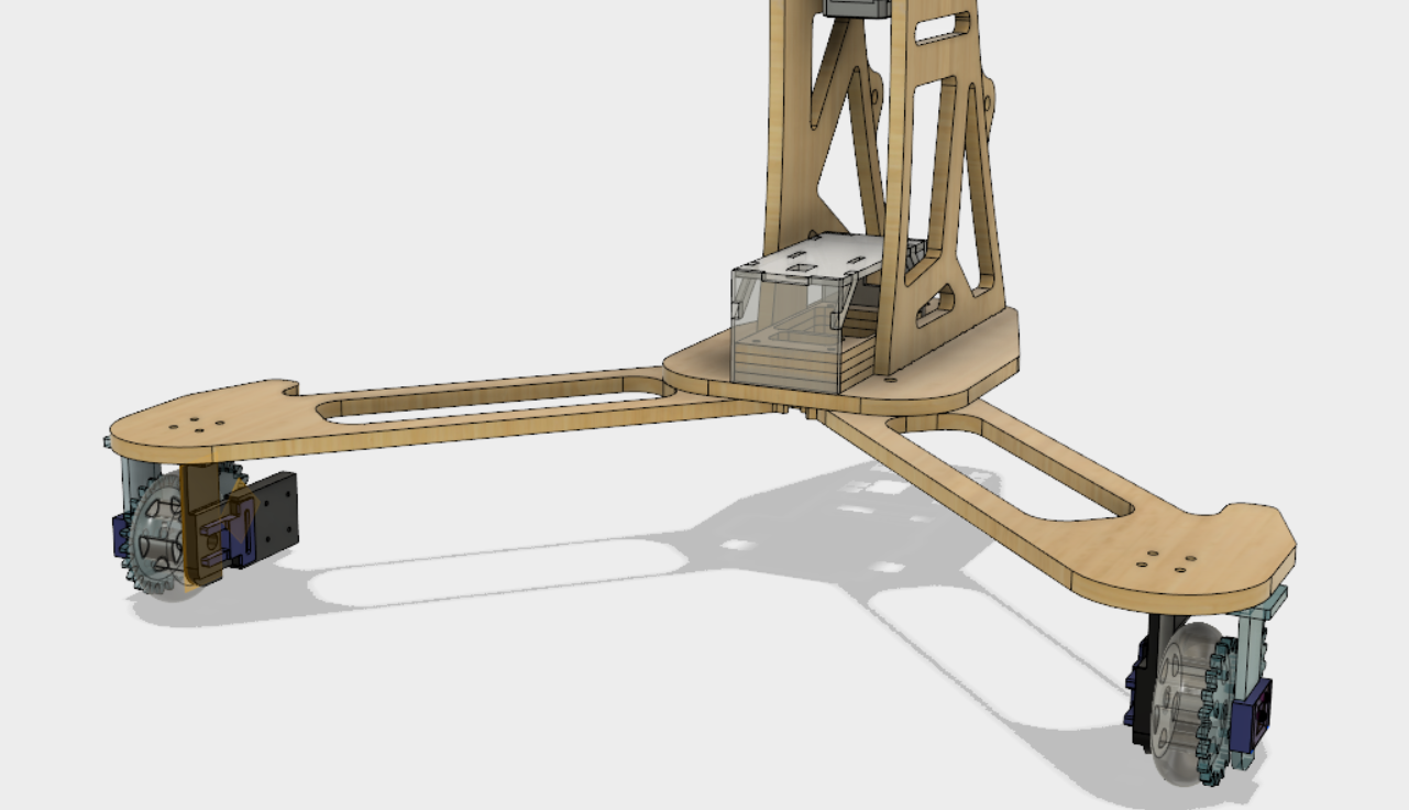
The frame
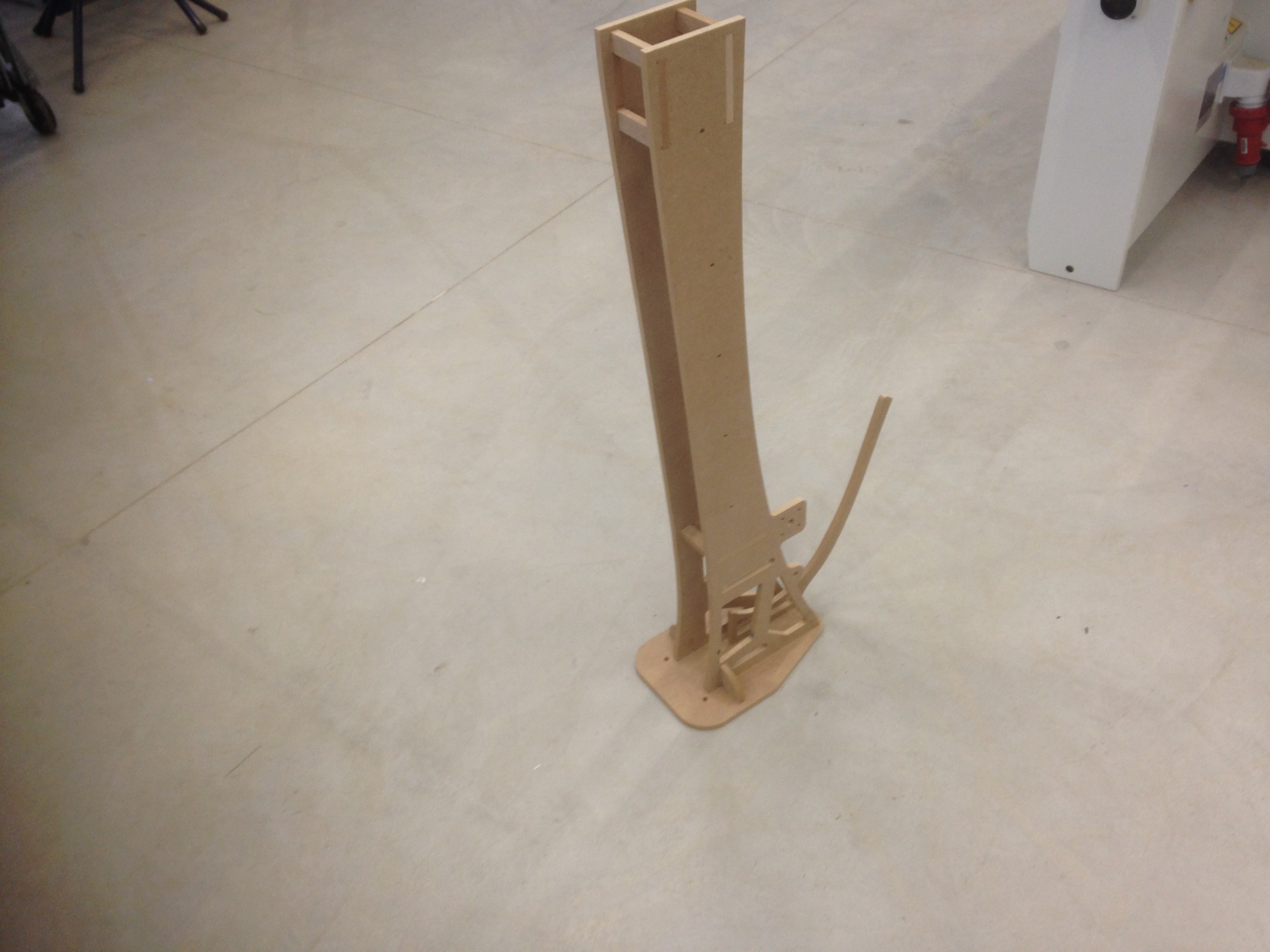
Here is my basic design for the bot's frame. The base, the so called drive module will hold the under carriage as well as electronics bay and support the tower. The tower carries the camera and contains the drawer rails as well as a stepper motor to extend it. The initial idea was to use a push chain to raise the camera, which was later replaced by threaded rod simular to the axis actuators of many CNC machines. To enable compact transportation, I split the design in half in z and the arms of the base are designed foldable.
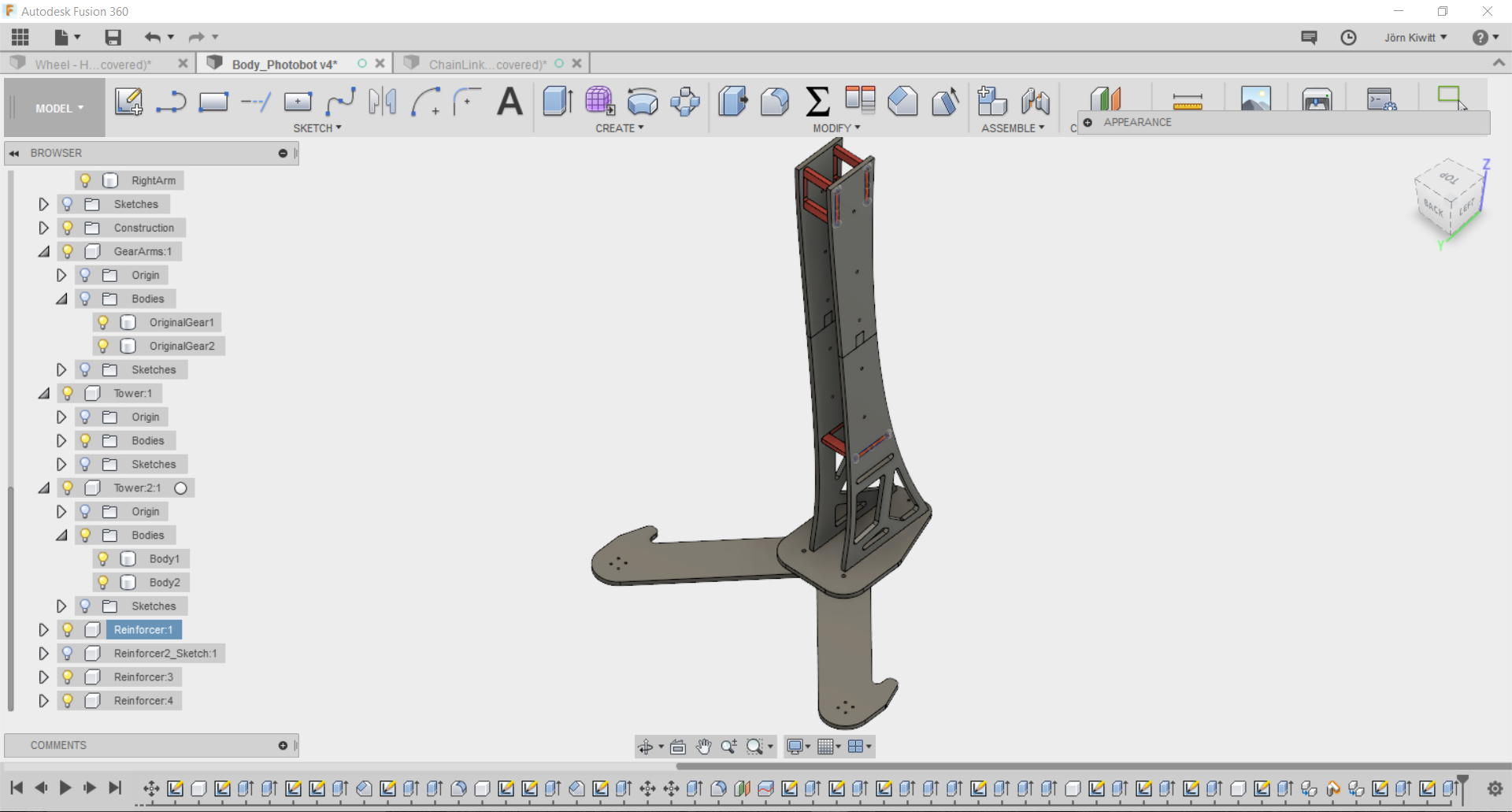
I finally added some reinforcing elements which will later also carry the actuator for raising the camera.
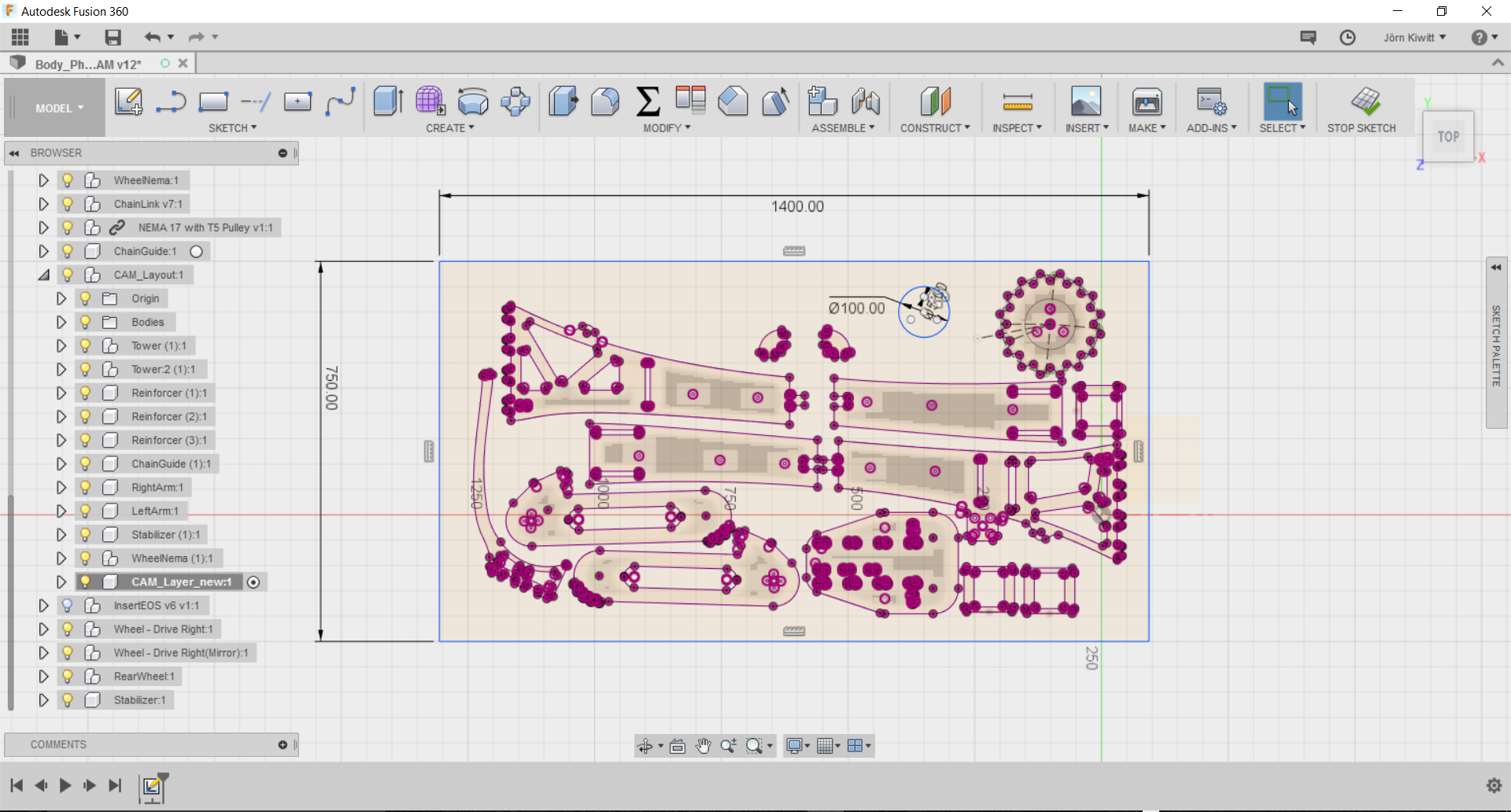
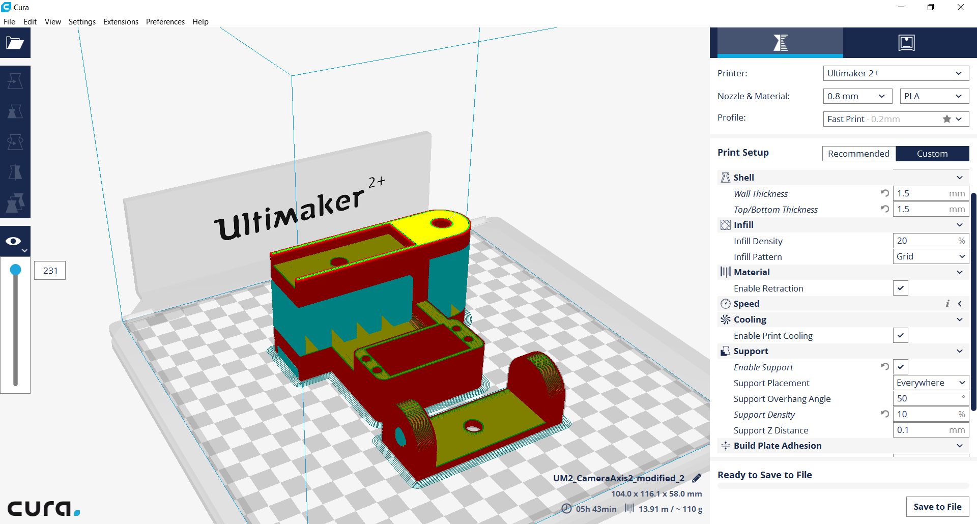
Making the frame
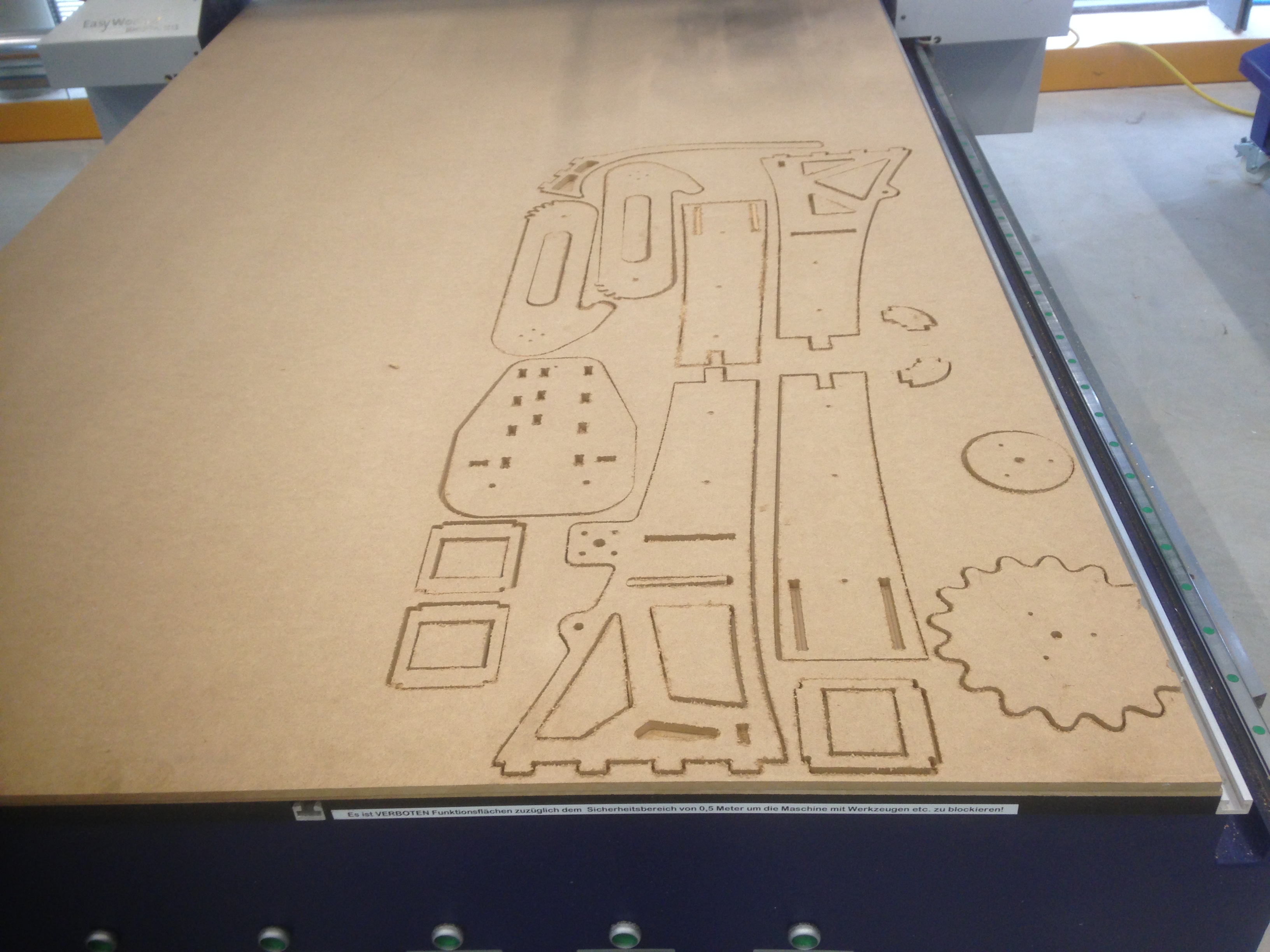
I made the frame using the EasyWorker CNC machine which I used earlier in the make something big assignment. All parts were laid flat using the align function in Fusion, projected a single sketch which was then exported to as *.dxf-file. Again, I took some tweaking in Rhino playing the explode and join function to account for all the doubles. I added to layers for the internal and the external cut and opened the file on the CNC machine. All settings can be retrieved from following images. Materialwise, I used MDF of 10 mm thickness.
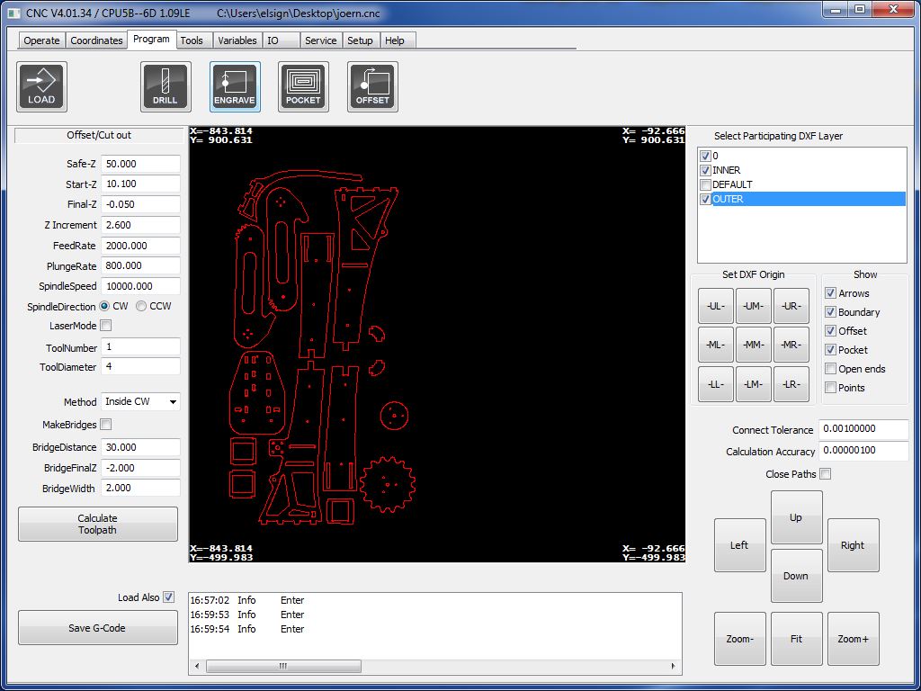
Milling took about 90 minutes. The press fits worked perfectly and gave a strong press fit, exactly as intended. After grinding of the edge for a clean finish, I used a mallet for the assembly.
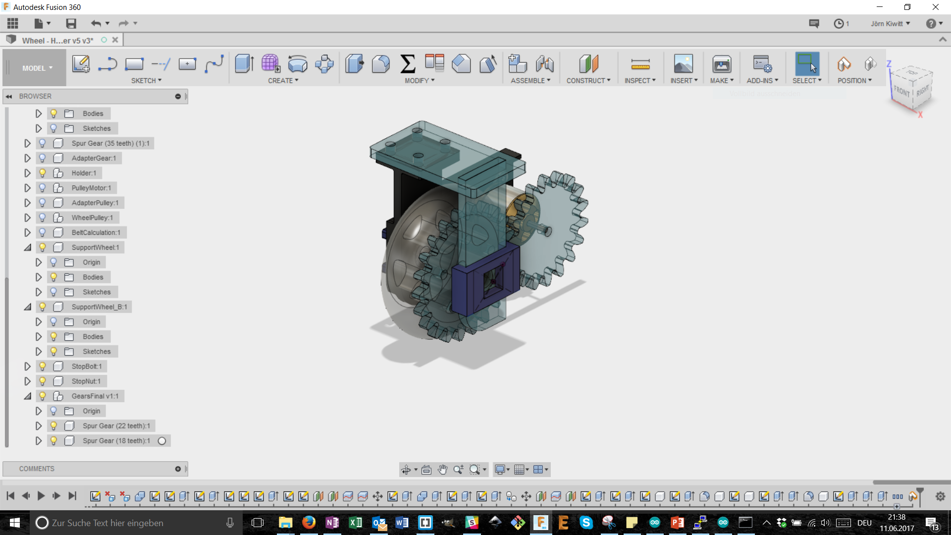
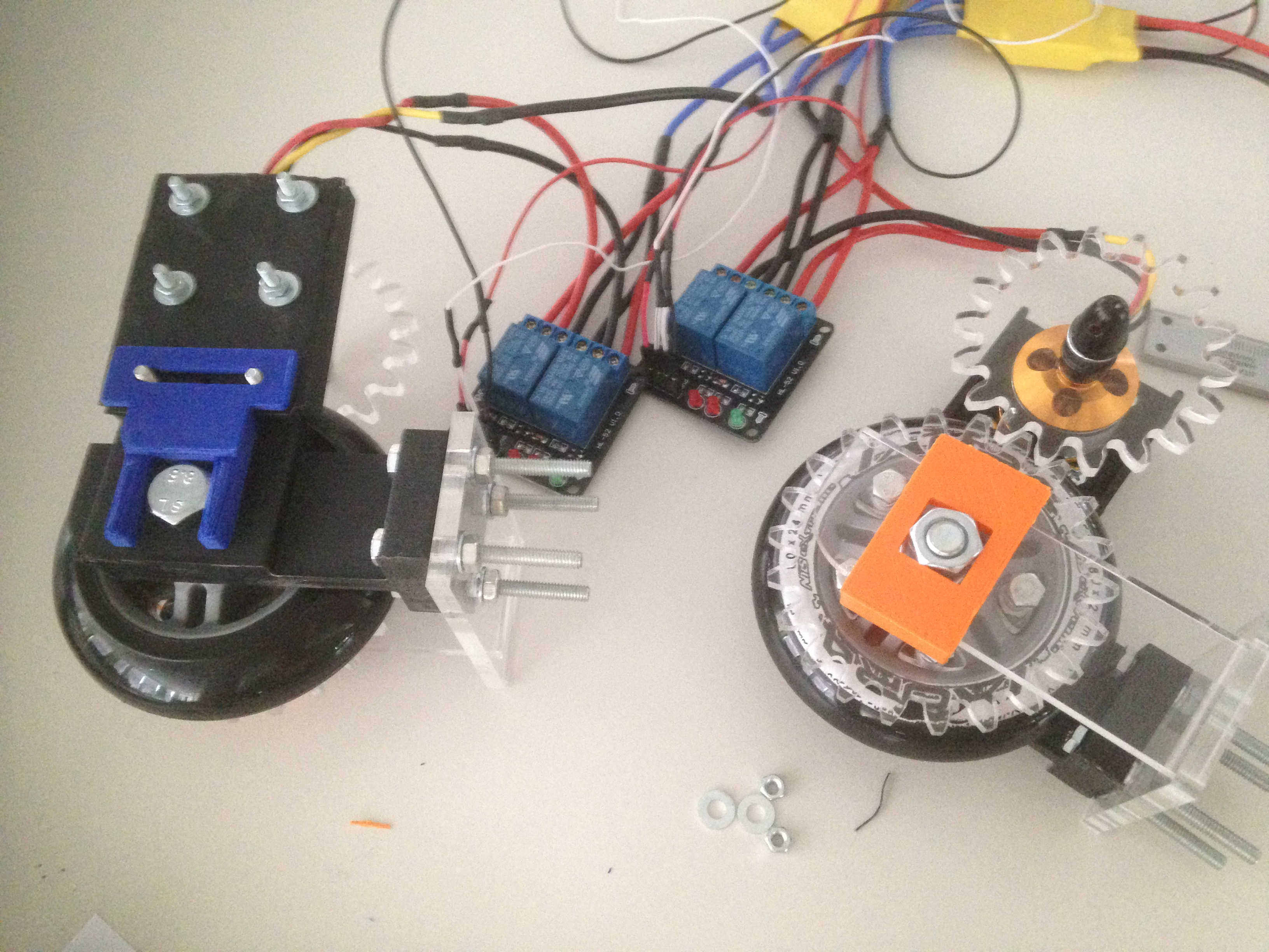
The drive module
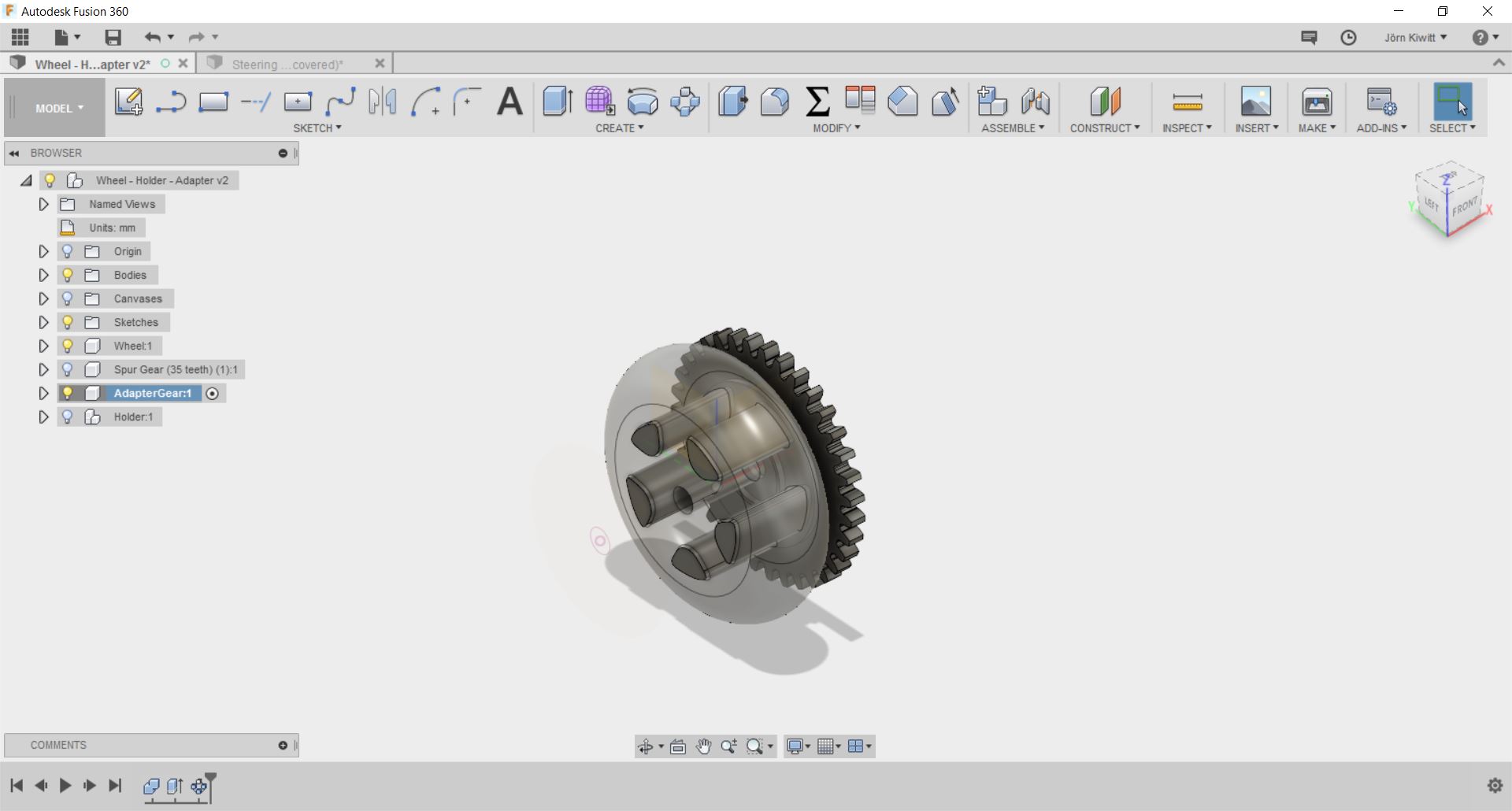
I finally decided to use acrylic gears of 6 mm thickness. The design was exported from Fusion 360 using the python script add-in SpurGear to generate the gear-wheel. Due to the size of the motor and wheel, I could not realize a very high transmission which turned out to be a downside. I used 100 % for power, 100 % for frequency and 6 % for speed on the laser cutter. Furthermore, small extensions from the gear-wheel were cut to fit into the slot of the wheels transmitting the torque.
The design of a mono-side carriage purely 3D printed turned out to be insufficient. The necessity for good alignment to to the gear-wheel could only be solve be adding some components to have the shaft supported on both sides of the wheel.
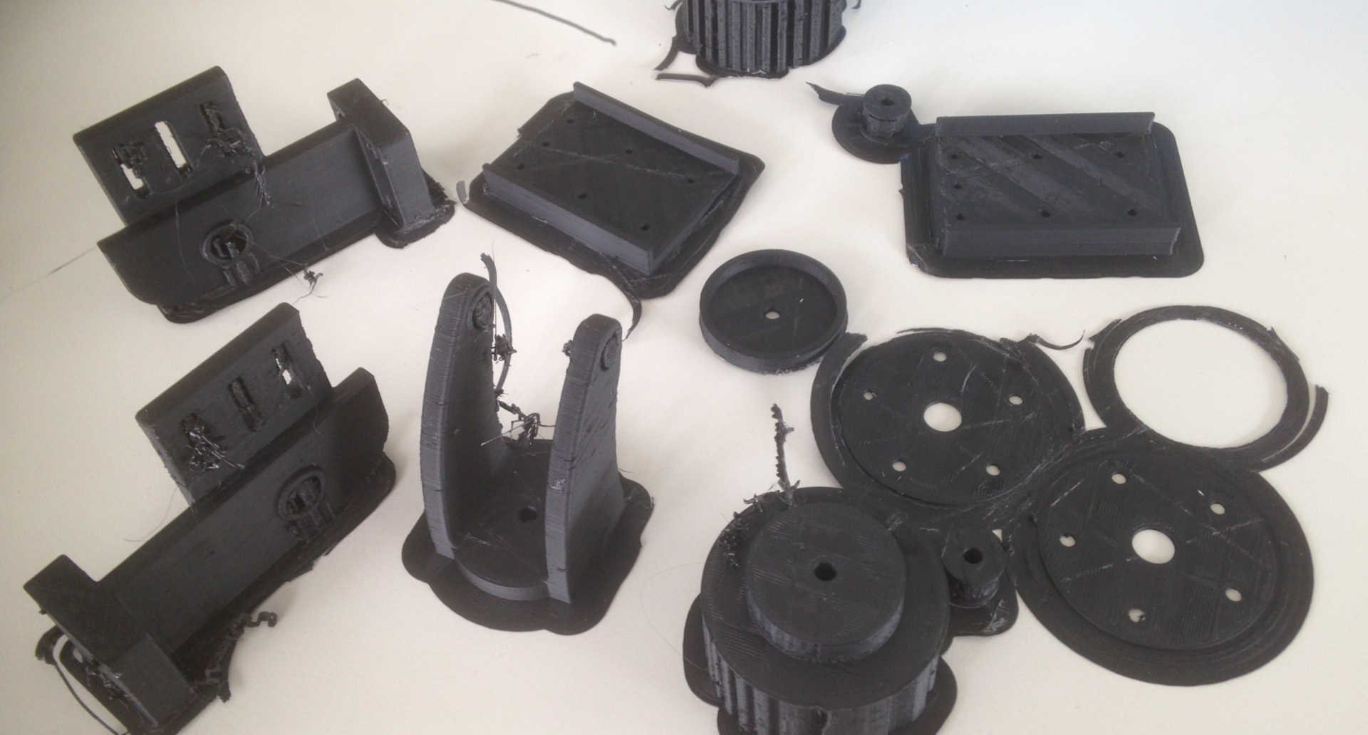
These additional parts were again laser cut from 6 mm acrylic. All nuts and bolts apart from the shaft were secured with LOCTITE.
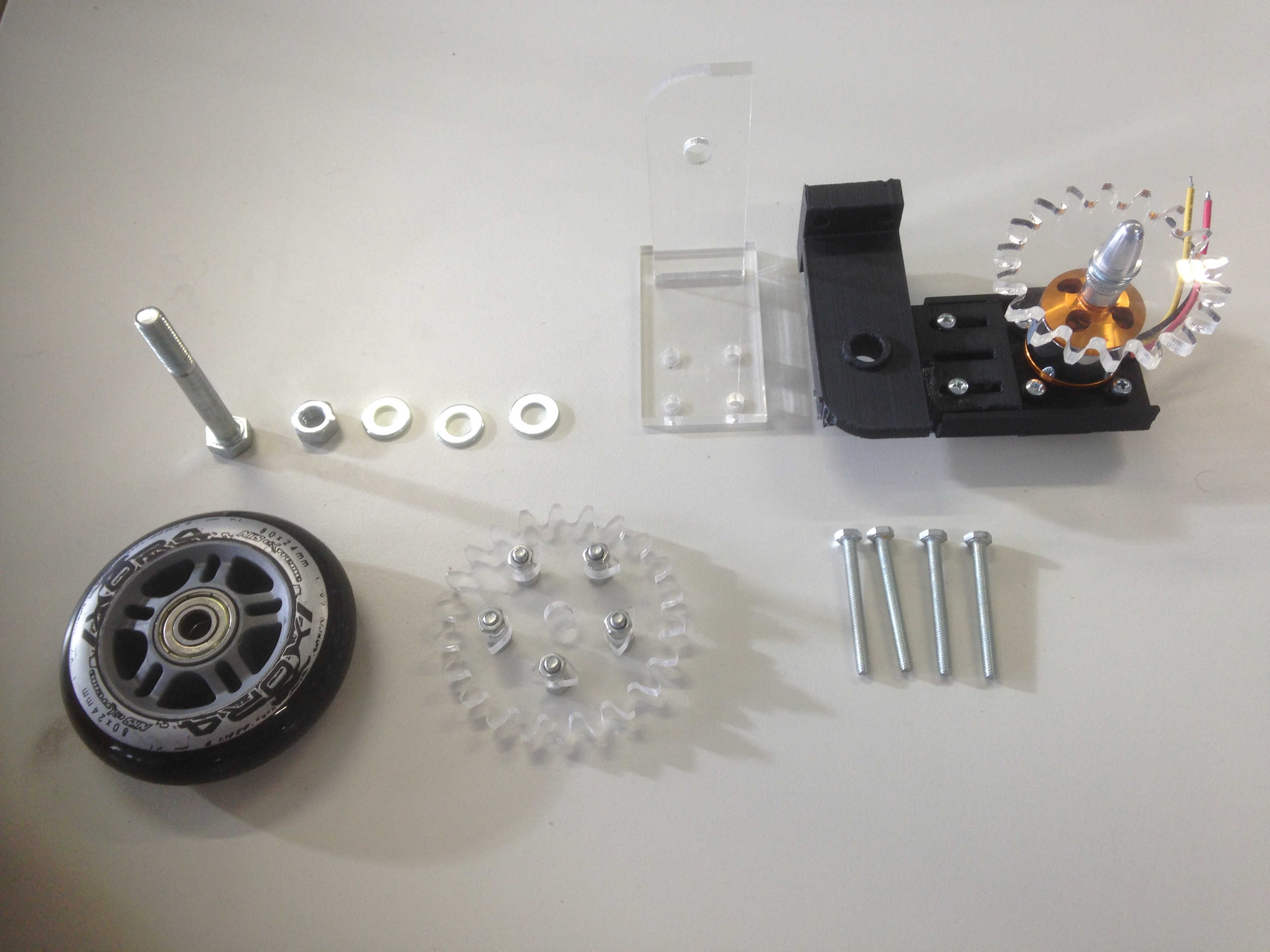
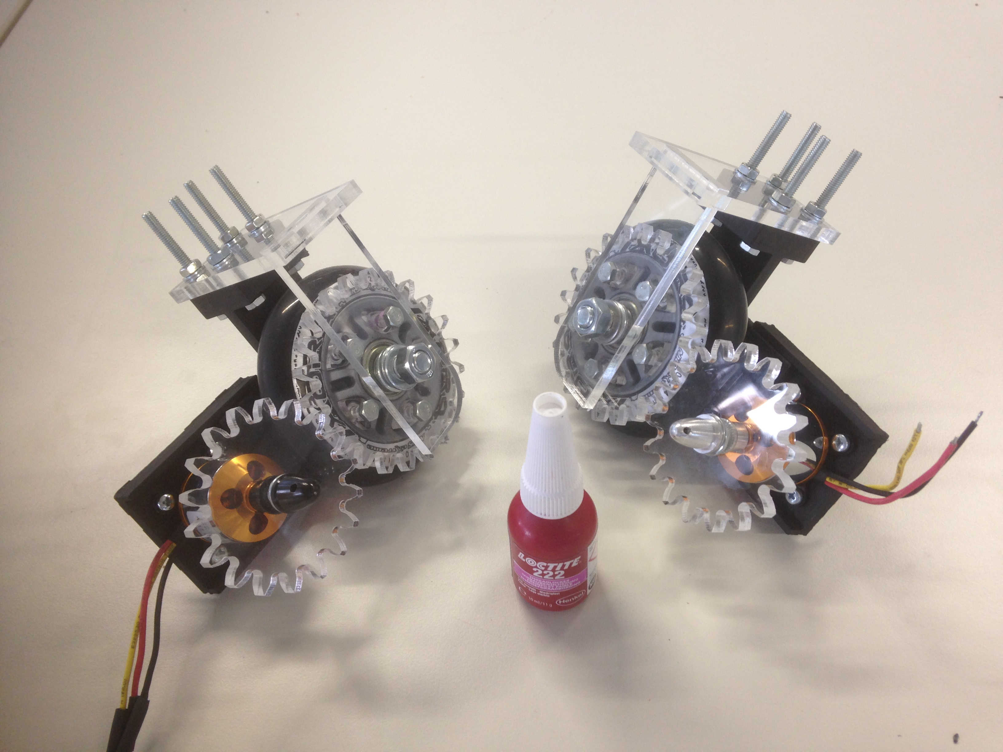
Now, it was time for a first test. I attached an ESC and did a first test of the geared drive use a remote control to send a PWM signal to the speed controller.
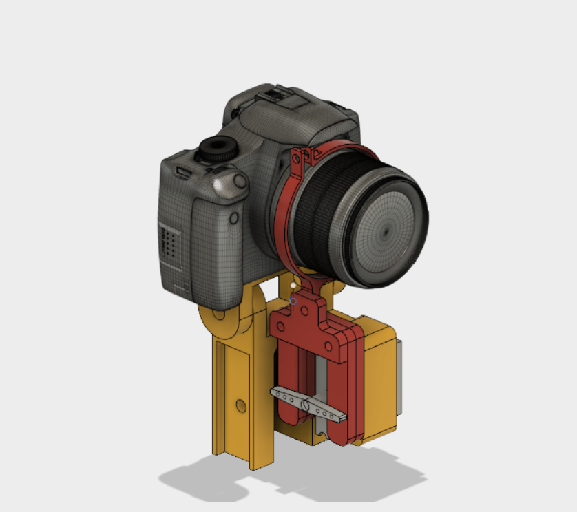
The camera module
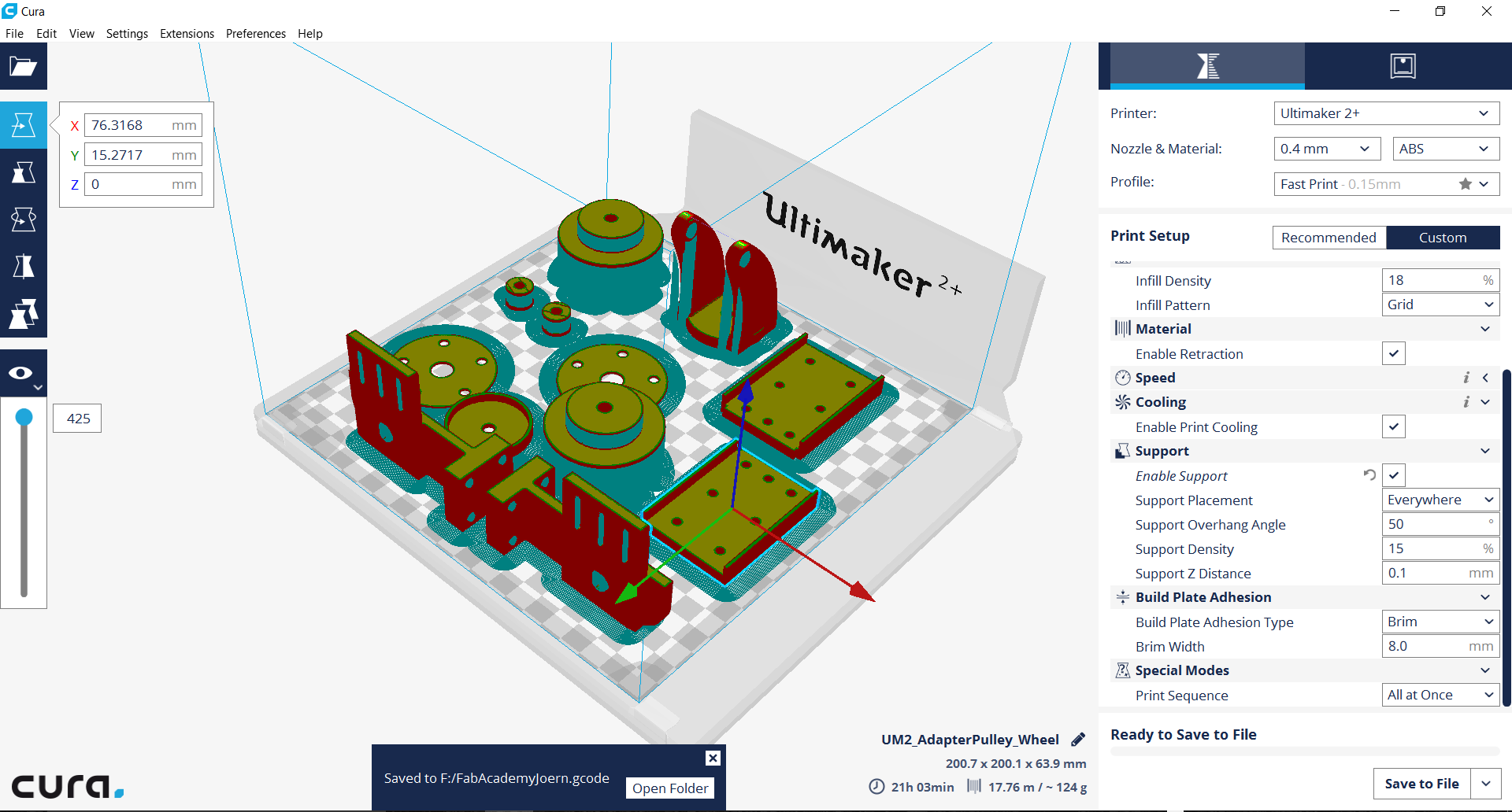
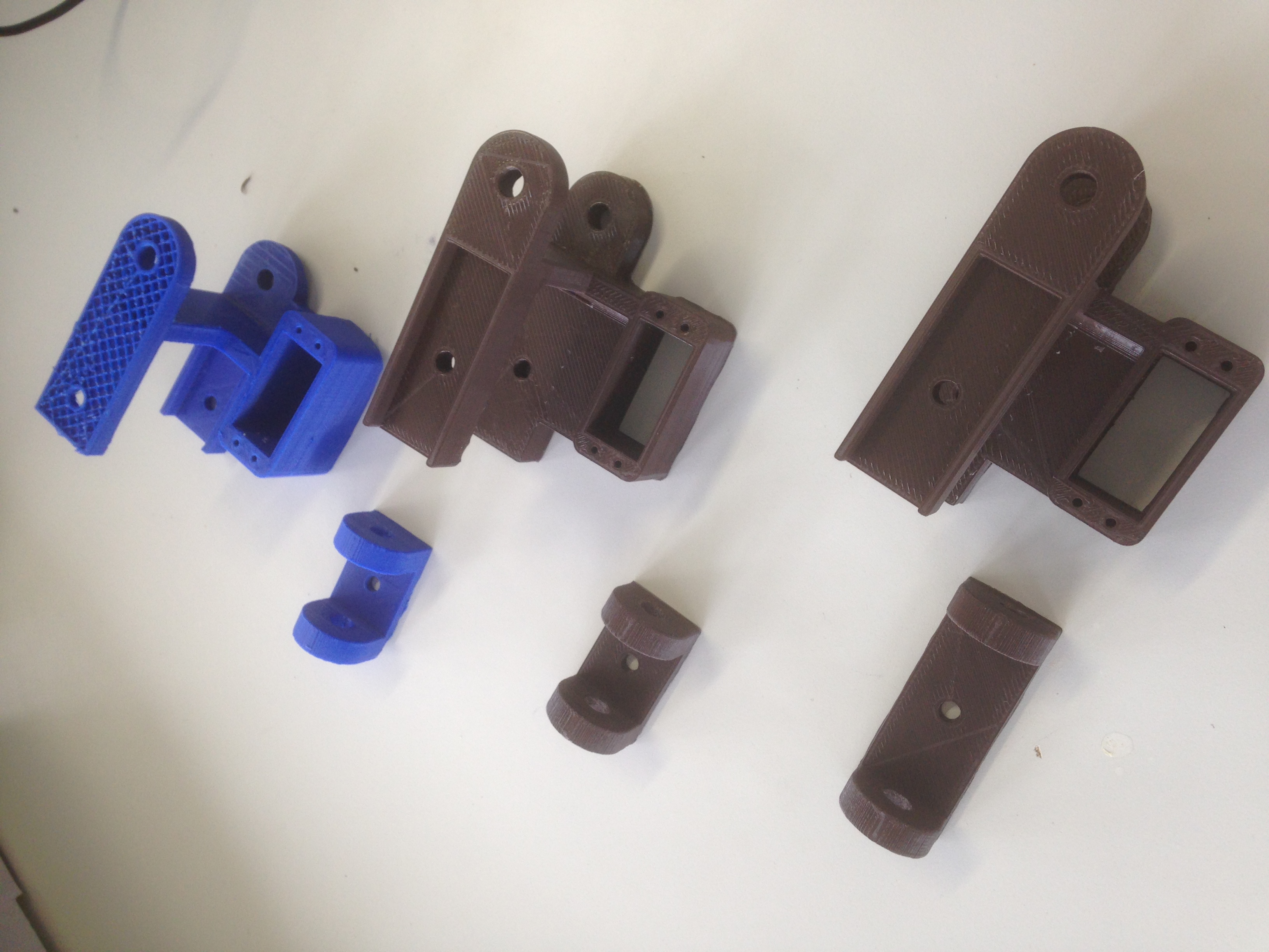
My final design consists of a simple servo socket which pushes up ring that is connected to the objective of the camera.
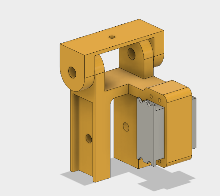
The design will be 3D printed in PLA.
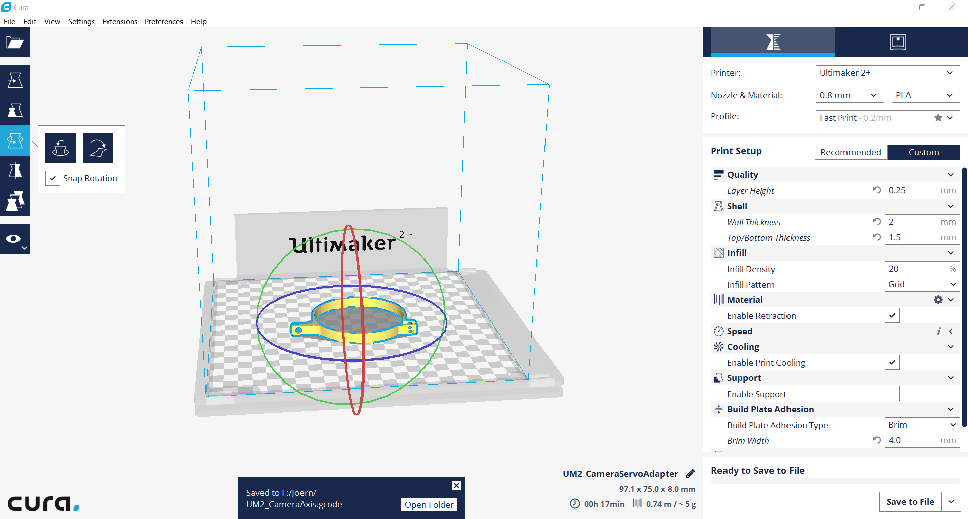
It had to make two iteration until the camera adapter fit nicely onto the guide rails. I used a simple laser cut design to build the connected using the servo housing as a guide rail for the pitch movement.
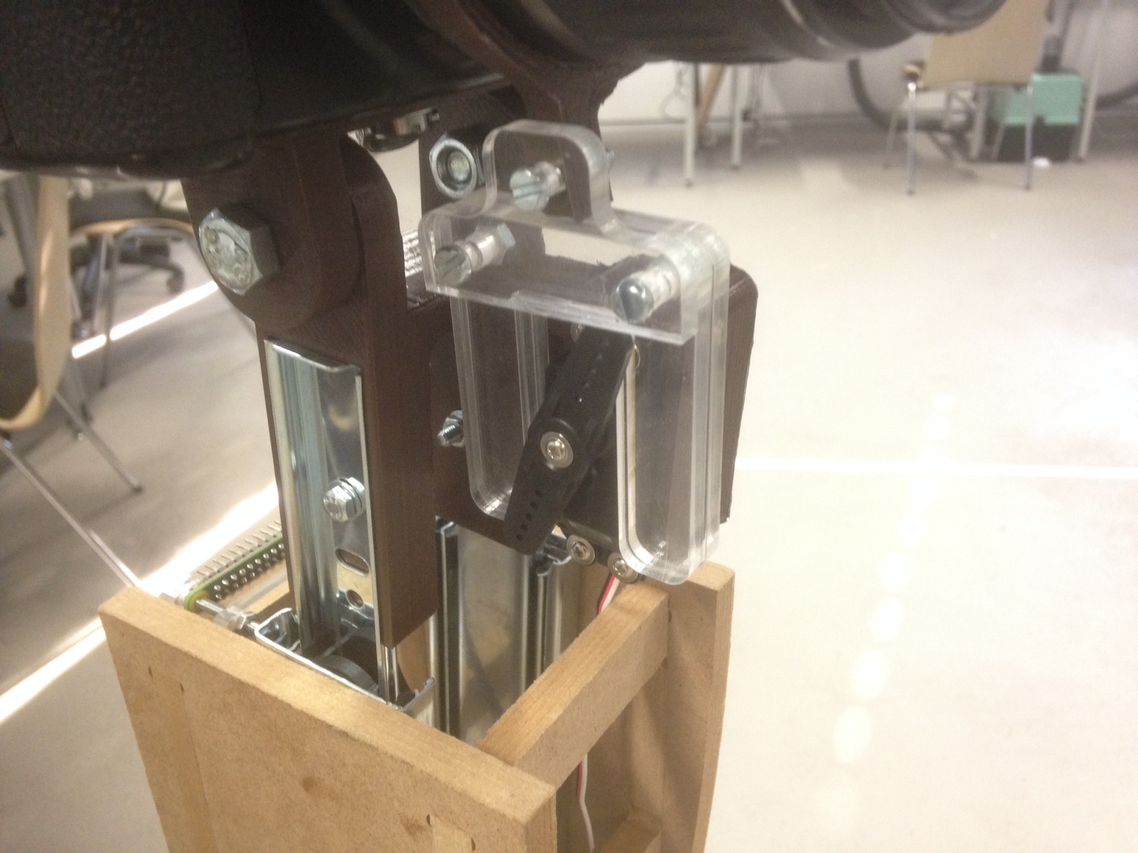
The next step was the kinematics to raise the camera.
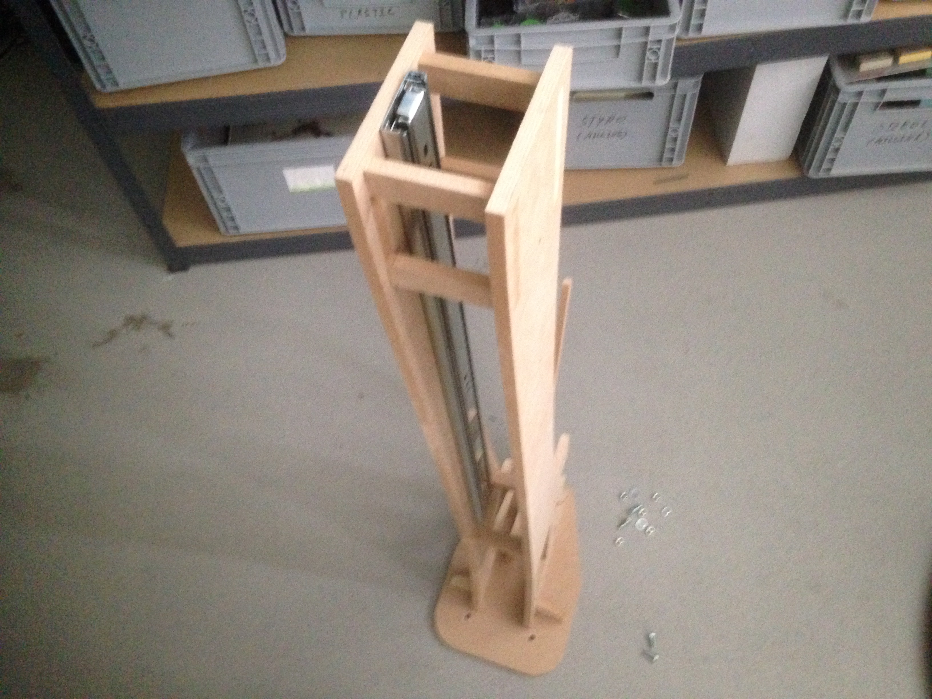
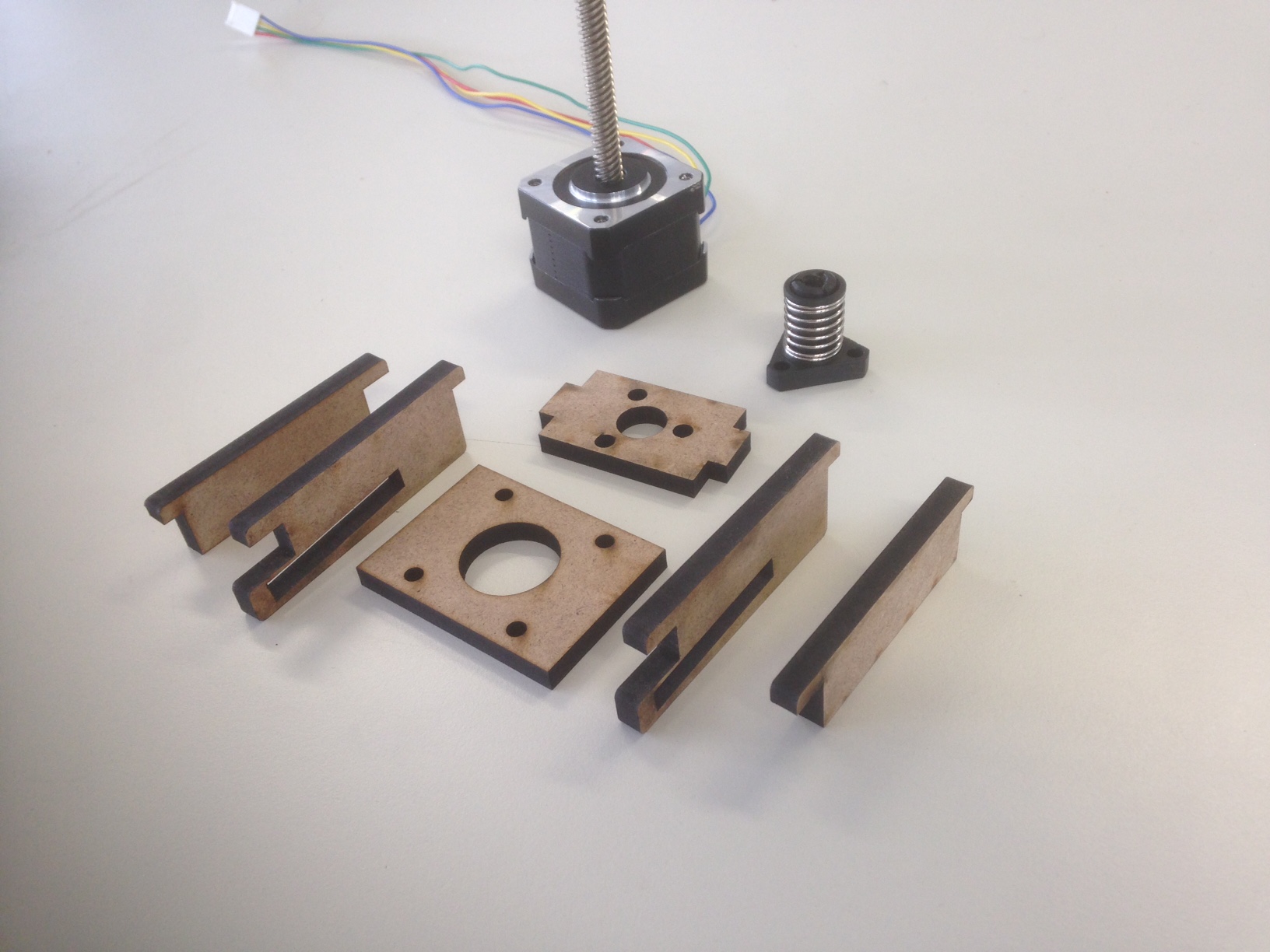
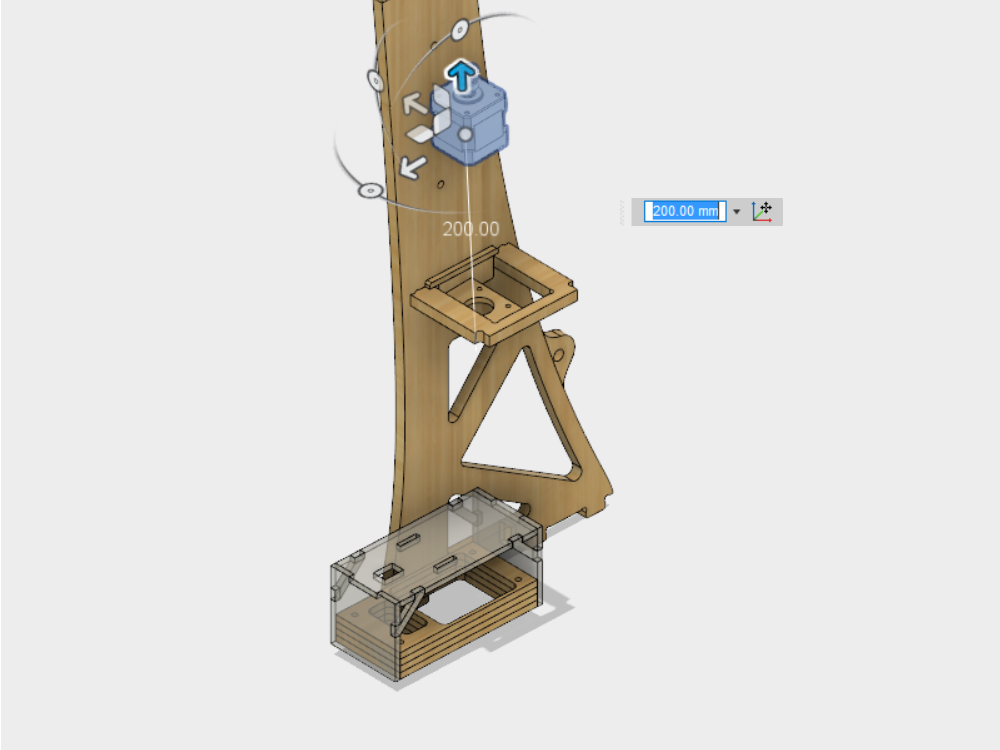
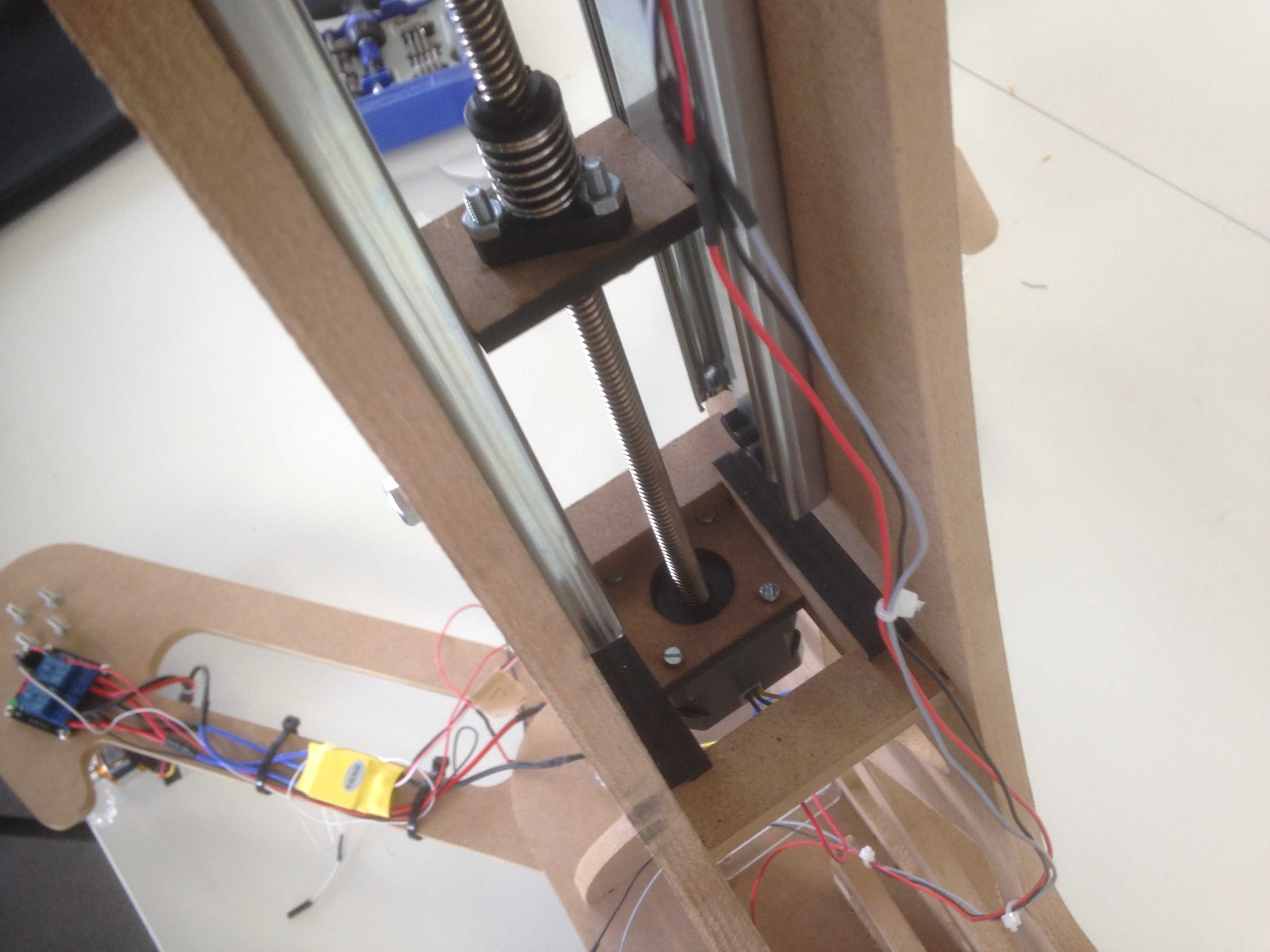
However, I never really came to implement this design, but went for a simpler one driven by a threaded rod with the stepper motor on the lower end. Suitable adapter were laser cut from 5 mm MDF. I used rails of a drawer to guide the movement. Fully extended, this would give an extra height of 70 cm but due to the limited rod length it only extended to around 30 cm so far.
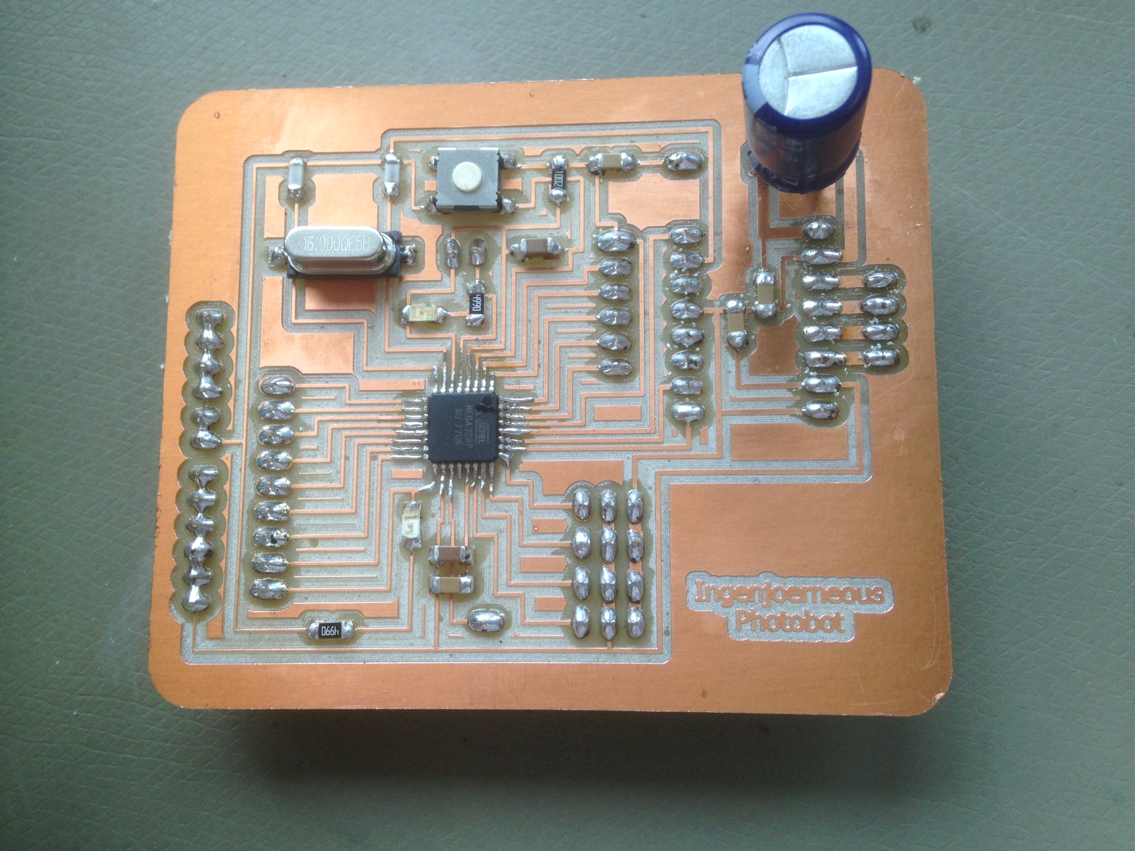
The electronics
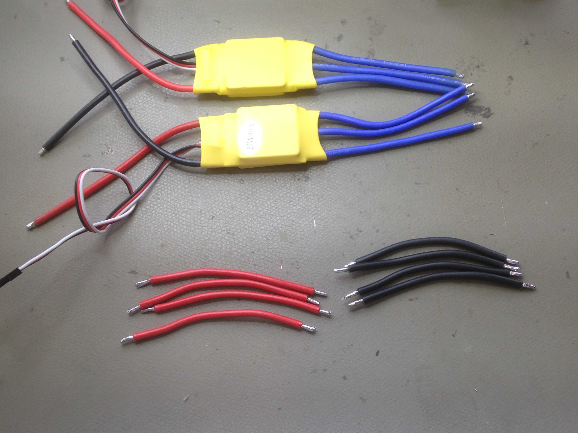
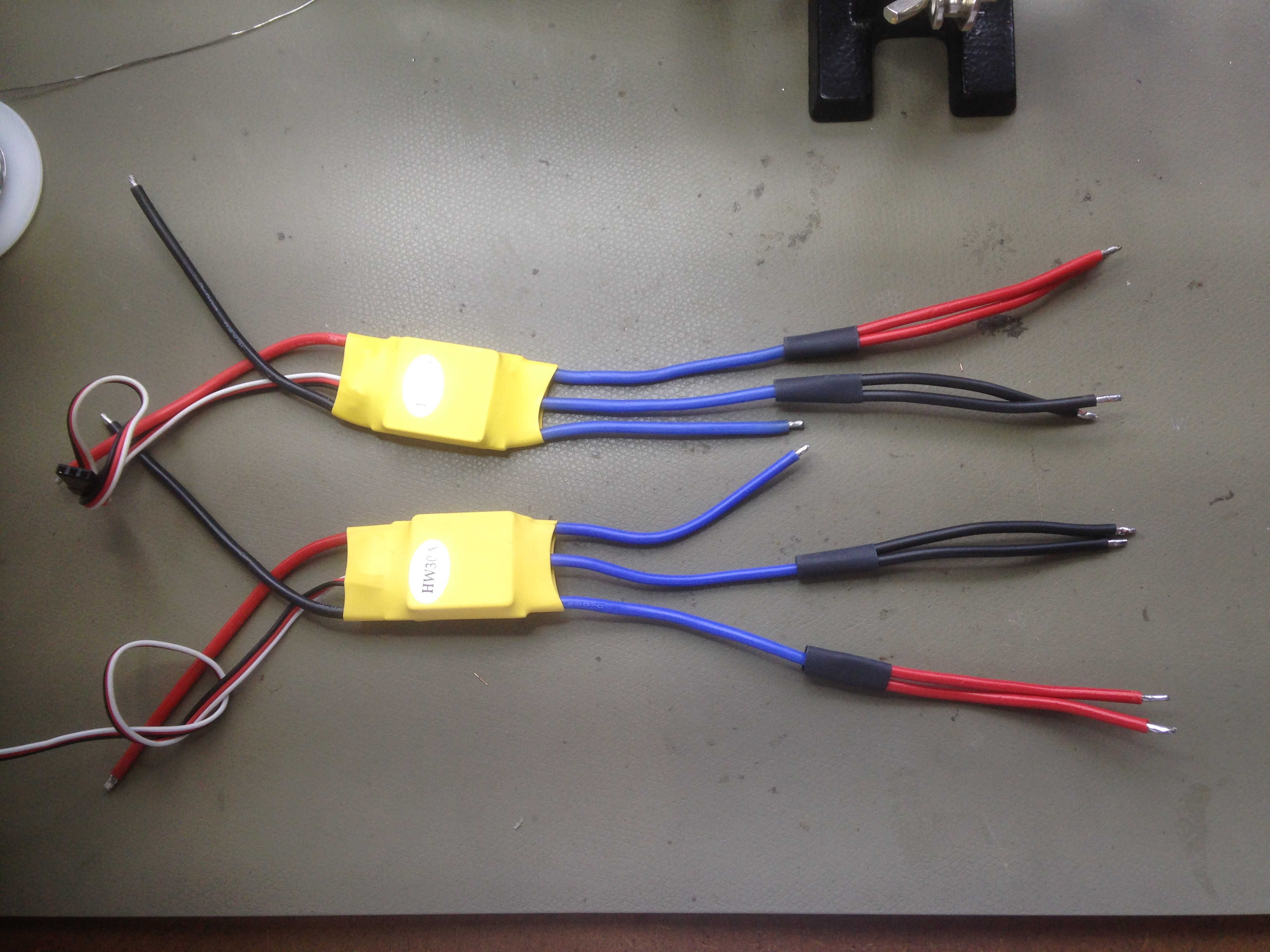
The bot will be controlled by a microcontroller board carrying the ATMega 328P. I will use three different output devices, two 2212 BLDC motors with 1000 kV, a stepper motor and 360 degree servo. The system will be powered by a 3S LiPo battery with high C-Rate. I have some 30C left, which I going to use. Of course, a higher capacity is also fine. Furthermore, I will need to integrate two ESCs for brushless motors as well as a board that distributes power to the output devices. To trigger the camera, a commercial wired remote control was hacked. The camera needs high levels on the auto focus and trigger to take a shot. Last but not least, I need a serial connection to the Raspberry pi which will be my WiFi receiver, hosting the Node JS server.
I started to planning with this layout.
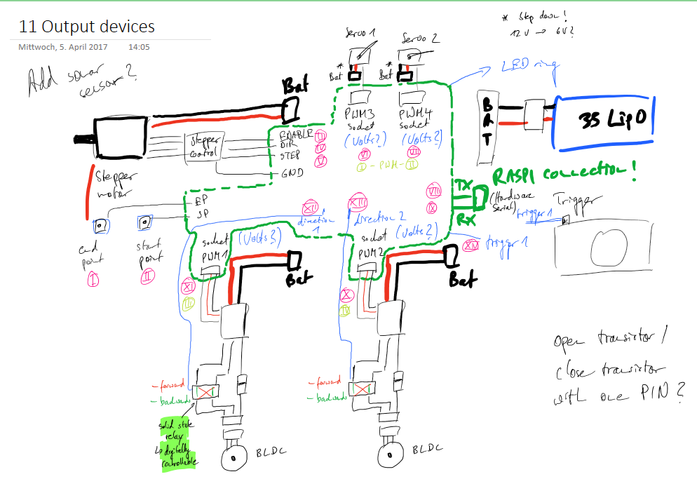
I ended up not implementing the second camera axis, enabling also portrait mode for the camera as I considered it unnecessary in the end.
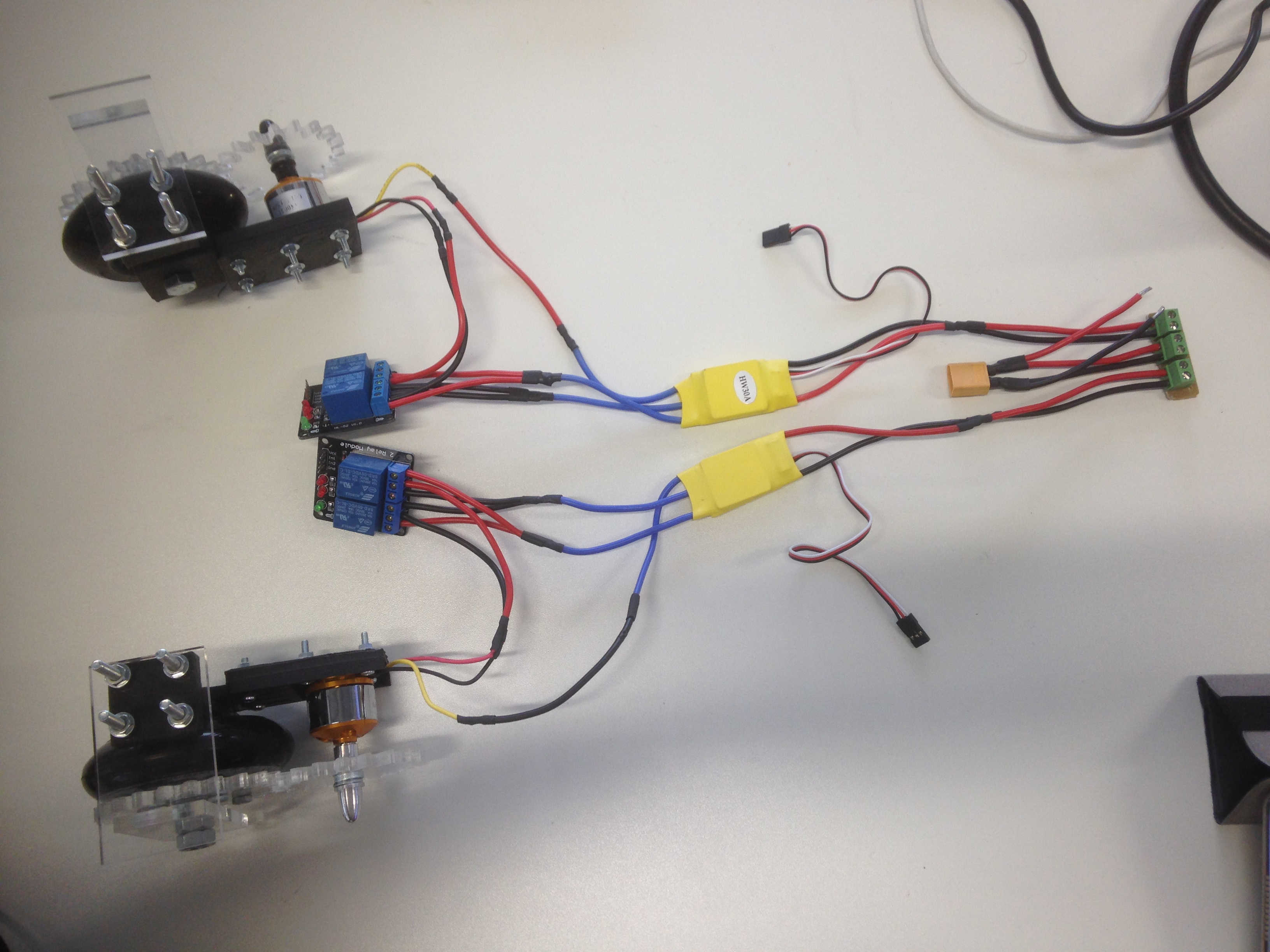
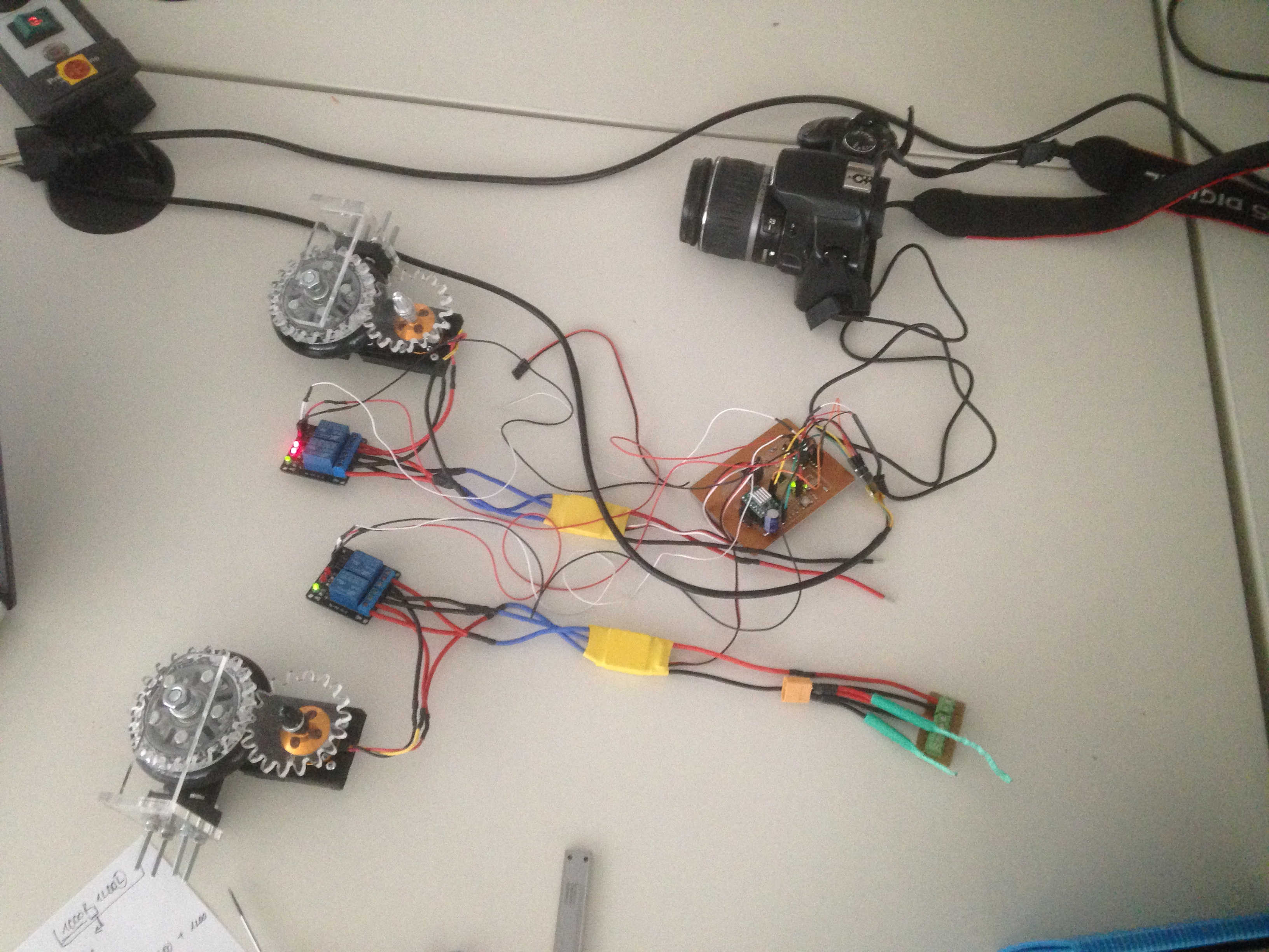
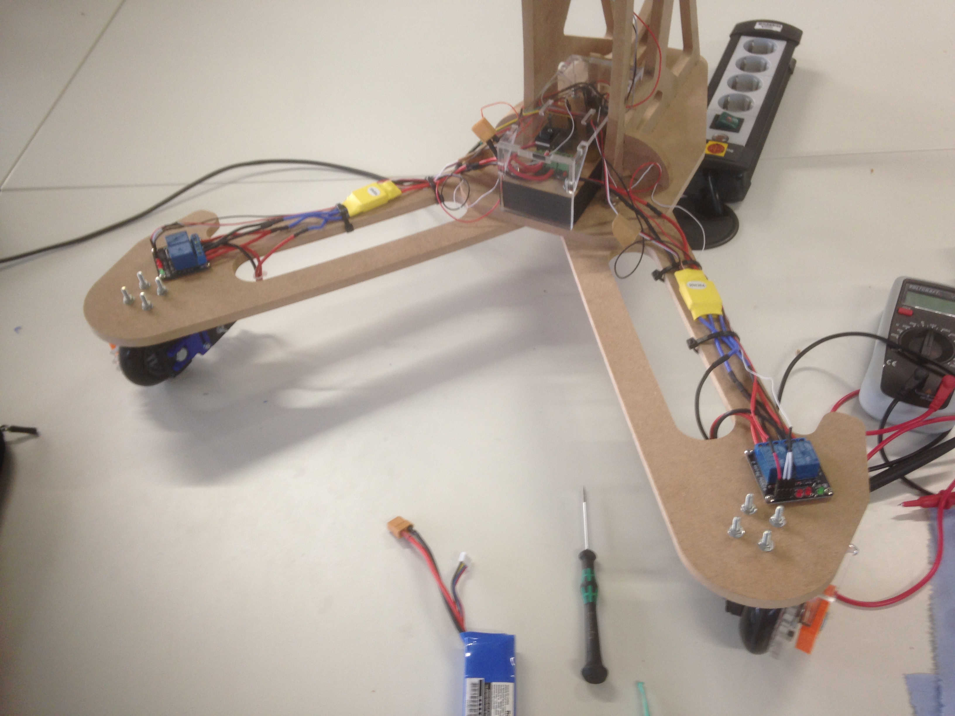
As the bot was moving based on the principle, I continued to assemble the other ESC as well as a power distribution board and the microcontroller board.
A added two relays on both sides to switch the turning direction of the BLDC motor.
I designed a simple power distribution board to route battery power to the to BLDC motors and the stepper motor driver on the modified Satshakit.
It turned out that the wires to the plug of the battery were switched, which caused short circuits. As the motor need to turn in both direction, I used relays to switch two wires of the motor to change from CW to CCW, i. e. forward an backward. As both relays have to switch at the same time, the two pins on the relay board can be bridged.
The microcontroller board also carries the Pololu stepper motor driver. As I burnt my board a week before the final presentation, I made a new one putting the female sockets to the bottom. More details can be found in the documentation of week 10.
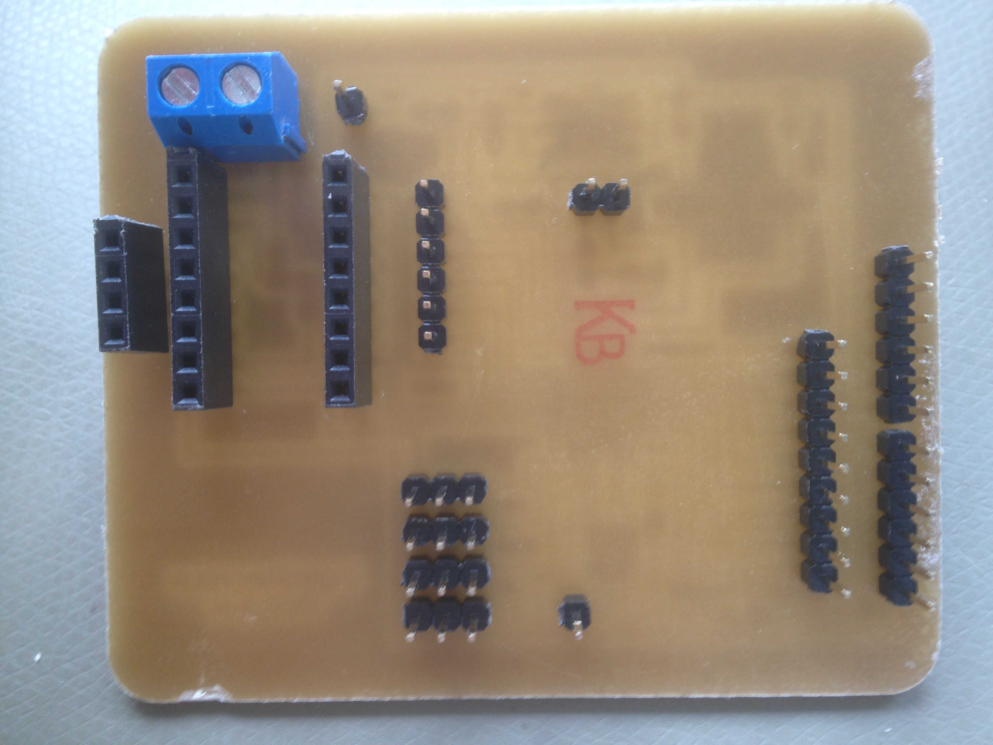
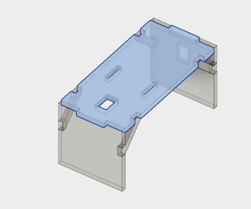
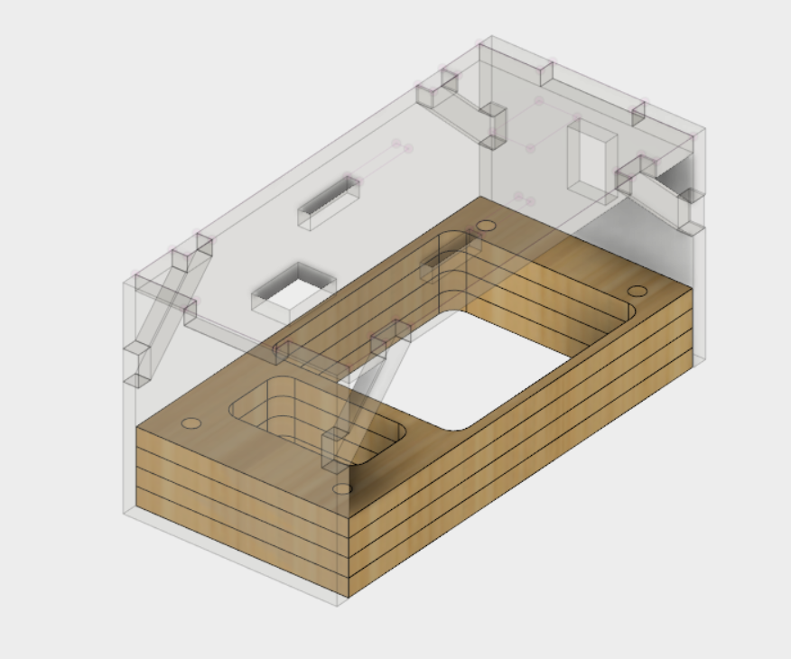
The circuit board are integrated into the electronics bay. It's a laser cut compartment from MDF covered with acrylic. The bay is integrated at the bottom of the bot.
Programming the microcontroller
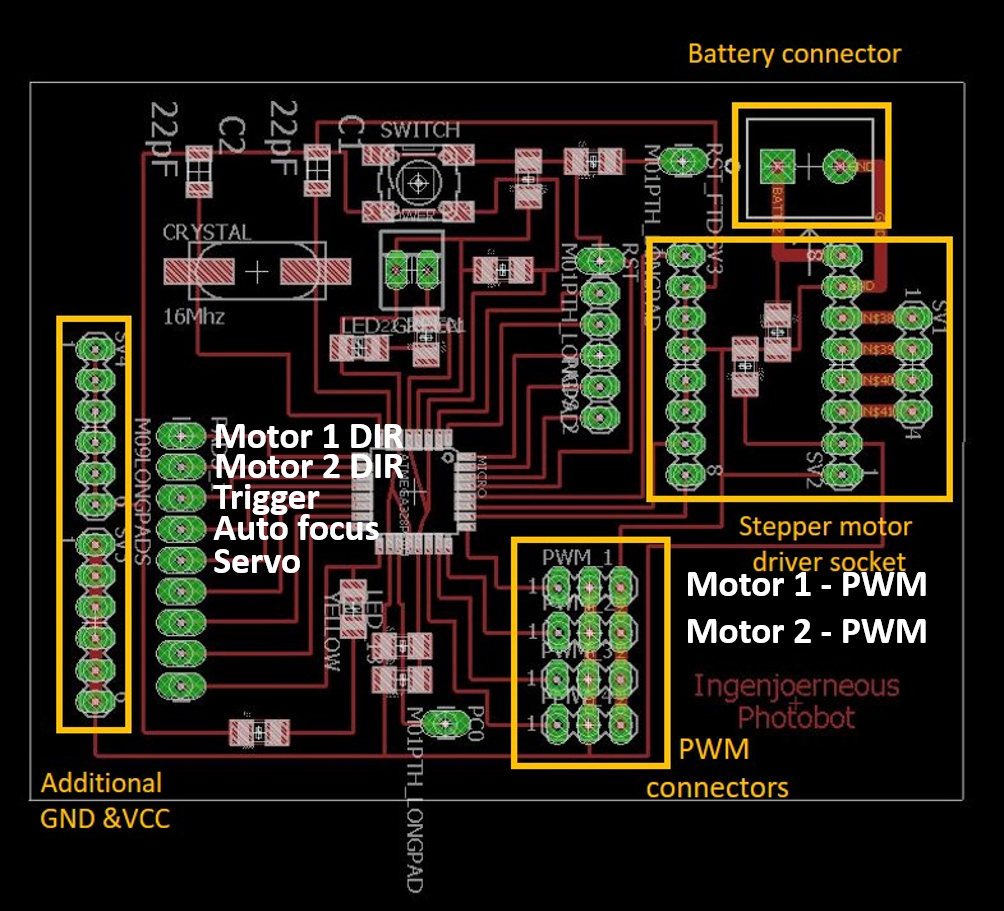
First, I connected all devices to the microcontroller board. Below, you can find the final pinout.
I choose the following physical connections:
| Function | Microcontroller pin | Arduino IDE pin |
|---|---|---|
| Motor 1 – PWM | PC2 | A2 |
| Motor 1 – Dir | PD5 | 5 |
| Motor 2 – PWM | PC1 | A1 |
| Motor 2 – Dir | PD6 | 6 |
| Trigger | PD7 | 7 |
| Auto focus | PB0 | 8 |
| Servo pin | PB1 | 9 |
As the goal was to control everything remotely, I programmed the microcontroller so that each component could addressed by a serial command. The commands were separated by tokens. E. g. L for left motor, R for the right motor, C for camera, B for both motors as well as S for the servo control.
I won't elaborate on all the initialization parameters, but briefly describe the function in the code.
Catch token
On receiving one of the above mentioned tokens, a boolean variable is set true. This is then handled by an if-condition that sets the output signals accordingly.
 while(Serial.available()>0){   // if some data come to the serial it will be passed to the speedValue

   // Recieve data from Node and write it to a String (read until end sign comes!)
   while (Serial.available() && pwmComplete1 == false && pwmComplete2 == false && triggeredCamera == false && stepperControl == false && pitchControl == false && danceTrigger == false && bothMotorsTrigger == false) {
      char inChar = (char)Serial.read();
      // Motors
      if(inChar == 'R'){  // end character left motor
        pwmComplete1 = true;
        Serial.print("R: ");
      }
      if(inChar == 'L'){  // end character left motor
        pwmComplete2 = true;
        Serial.print("L: ");
      }
      // Camera
      if(inChar == 'C'){
        triggeredCamera = true;
        Serial.print("C: ");
      }
      // Stepper Motor
      if(inChar == 'S'){
        stepperControl = true;
        Serial.print("S: ");
      }
      // Pitch Servo
      if(inChar == 'P'){
        pitchControl = true;
        Serial.print("P: ");
      }
      if(inChar == 'D'){
        danceTrigger = true;
        Serial.print("D: ");
      }
      if(inChar == 'B'){
        bothMotorsTrigger = true;
        Serial.print("B: ");
      }
      else{
        inputString += inChar;
      }
   }
Handling conditions
After the token is caught, the stringToInt function is converting the strings from the serial line to an integer value. This way of interfacing serial commands was existing before, combined by sending data from a webinterface via socket.io, which I will talk about in the next section.
int stringToInt()
  {
      char charHolder[inputString.length()+1];
      inputString.toCharArray(charHolder,inputString.length()+1);
      inputString = "";
      int _recievedVal = atoi(charHolder);
      return _recievedVal;
  }
The following condition handles the turning direction of a motor by setting the relay to high or low, as well as the turn right handling. This will set the PWM signal of the ESC to 1500 for one second and pull it back to zero afterwards. This way the robot is moving only stepwise, so in case of a loss of signal, no uncontrolled movement can happen.
    // Switch PWM signal / motor speed 1 R --> Serial.available is 0, buffer read
    //if(!Serial.available() && pwmComplete1 == true)
    if(pwmComplete1 == true)
    {
      // convert String to int.
      int recievedVal1 = stringToInt();

      speedValue1 = recievedVal1;

      // Set direction motor 1
      if (speedValue1 > 0){
        digitalWrite(M1_Dir, HIGH);
        Serial.println(speedValue1);
        motor1.writeMicroseconds(speedValue1);  // here the values will be writen to the ESC
      }
      if (speedValue1 <0){
        digitalWrite(M1_Dir, LOW);
        speedValue1 =speedValue1*-1;
        Serial.println(speedValue1);
        motor1.writeMicroseconds(speedValue1);  // here the values will be writen to the ESC
      }

      // Button control turn right
      if(speedValue1 == 0){
        digitalWrite(M1_Dir, HIGH);
        motor1.writeMicroseconds(1500);  // here the values will be writen to the ESC
        digitalWrite(M2_Dir, HIGH);
        motor2.writeMicroseconds(1500);  // here the values will be writen to the ESC
        delay(1000);
        motor1.writeMicroseconds(0);
        motor2.writeMicroseconds(0);
      }

      pwmComplete1 = false;
    }
The camera section is giving a high level output to the auto focus pin first and then also pulling the trigger high an instant later.
// CAMERA Function
if(!Serial.available() && triggeredCamera == true){
// Take a shot:
    digitalWrite(pinAutoFocus,HIGH);
    delay(300);
    digitalWrite(pinTrigger,HIGH);
    delay(100);

  // Turn down
    digitalWrite(pinAutoFocus,LOW);
    delay(100);
    digitalWrite(pinTrigger,LOW);

  triggeredCamera = false;
}
The pitch servo is not as well suited for the purpose of a pitch servo as it was originally designed for the purpose of a winch motor on RC sailing boats. It therefore goes 360 degrees. By setting a speed for a certain period of time, the servo will set the pitch a few degree up or down, which will totally sufficient for adjustment.
// Pitch servo function
if(!Serial.available() && pitchControl == true){

    pitchPosition=stringToInt();
    Serial.println("pitchPosition: ");
    Serial.print(pitchPosition);

    //Test
     //pitchServo.write(pitchPosition);


    if (pitchPosition>0){
    // Up
      pitchServo.write(82);
      delay(200);
      pitchServo.write(95);
    }
    else{
    // Down
      Serial.println("reverse");
      pitchServo.write(100);
      delay(200);
      pitchServo.write(95);
    }

  Serial.println("End Servo");

  pitchControl = false;
  }
Finally, the stepper motor driver will get its position from a slider in the web interface. As I do not have implemented end stops, the additional steps possible in each direction have to respect the current position and step up or down from there.
// Stepper function
if(!Serial.available() &&  stepperControl== true){

// decide direction
  int steps = stringToInt();
  Serial.println(steps);

Serial.print("steps: ");
Serial.println(steps);

// If new position below old reverse direction
  if (steps<startStep){
    // Go down
    digitalWrite(dirPin,HIGH);
    for(startStep; startStep >= steps; startStep--) {
      //Serial.println("Go Down");
      digitalWrite(clkPin,HIGH);
      delayMicroseconds(stepSpeed);
      digitalWrite(clkPin,LOW);
      delayMicroseconds(stepSpeed);
    }
  }
  else{
    // Go up
    digitalWrite(dirPin,LOW);
    for(startStep; startStep <= steps; startStep++) {
      //Serial.println("Go Up");
      digitalWrite(clkPin,HIGH);
      delayMicroseconds(stepSpeed);
      digitalWrite(clkPin,LOW);
      delayMicroseconds(stepSpeed);
    }
  }

   startStep=steps;

   Serial.print("startStep: ");
   Serial.println(startStep);
   stepperControl = false;
  }

  } // close Serial bracket
}   // End loop
Application & interfacing
Local host communication
As launching my JavaScript code on the server won't be too difficult, I did the modifcation of the code as well as testing in the localhost environment.
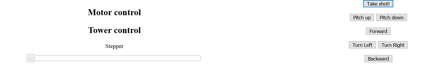
I basically had to add another GUI element in the interface.html. Initially, I thought about using sliders to control the speeds of each motor individually.
<h2>Motor control
	   <div id="btnHolder">
	</div>
	   <p id="sliderTxt">Throttle 1 - Left</p>
	   <div id="throttleLeft"></div>

	   <div id="btnHolder">
	</div>
	   <p id="sliderTxt">Throttle 2 - Right </p>
	   <div id="throttleRight"></div>
   </div>
I finally used the document.ready function, calling socket.io to send data to the Raspberry Pi.
    $(document).ready(function() {
        // Camera trigger
        $('#check').click(function() {
            toggleVal += 1;
        toggleVal %= 2;
        iosocket.emit('Camera',toggleVal);
        });

		// Pitch Up
		$('#pitchButtonUp').click(function() {
            pitchToggleVal = 1;
	    iosocket.emit('Pitch',pitchToggleVal);
		});

		// Pitch Down
		$('#pitchButtonDown').click(function() {
            pitchToggleVal = -1;
	    iosocket.emit('Pitch',pitchToggleVal);
		});
		// Turn right
		$('#ThrottleRightButton').click(function() {
            turnVal = 0;
	    iosocket.emit('throttleLeft',turnVal);
		});

		// Turn left
		$('#ThrottleLeftButton').click(function() {
            turnVal = 0;
	    iosocket.emit('throttleRight',turnVal);
		});

		// Forward
		$('#Forward').click(function() {
            turnBoth = -1;
	    iosocket.emit('BothMotors',turnBoth);
		});

		// Backward
		$('#Backward').click(function() {
            turnBoth = 1;
	    iosocket.emit('BothMotors',turnBoth);
		});
	});
Last but not least, I modified the server.js file in order to connect this element to the correct serial data.
socket.on('throttleRight', function(data) {
    serialPort.write(data + 'L');
});
socket.on('throttleLeft', function(data) {
    serialPort.write(data + 'R');
});

    });
Camera control
I extended the serial protocol by adding another button for the camera trigger to server.js file.
//  Camera
socket.on('Camera', function(data) {
    serialPort.write(data + 'C');
});
Everything was working in the localhost environment. I progressed to using the Raspberry Pi Zero as my receiver. Therefore, the Node code had to be send to the Pi.
Enable remote control
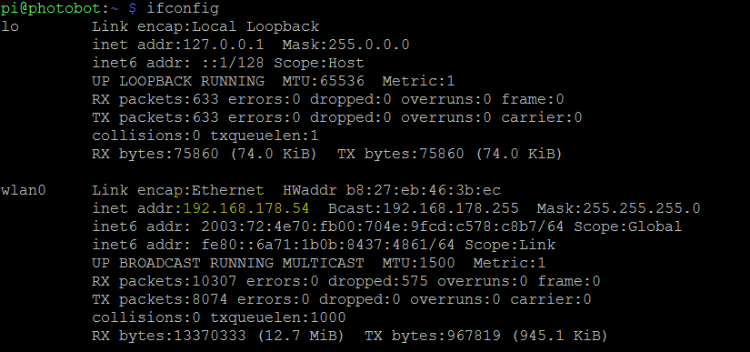
First, I had to find out how to control the raspberry pi from a remote desktop. Therefore, I retrieved the IP address of the pi by typing ifconfig into the command prompt. Be sure to activate SSH in the settings. I used Putty on my Windows machine, typed in the address with the default port 22. The login screen appears in your shell. Use pi and raspberry as the login credentials.
Remote control via remote desktop
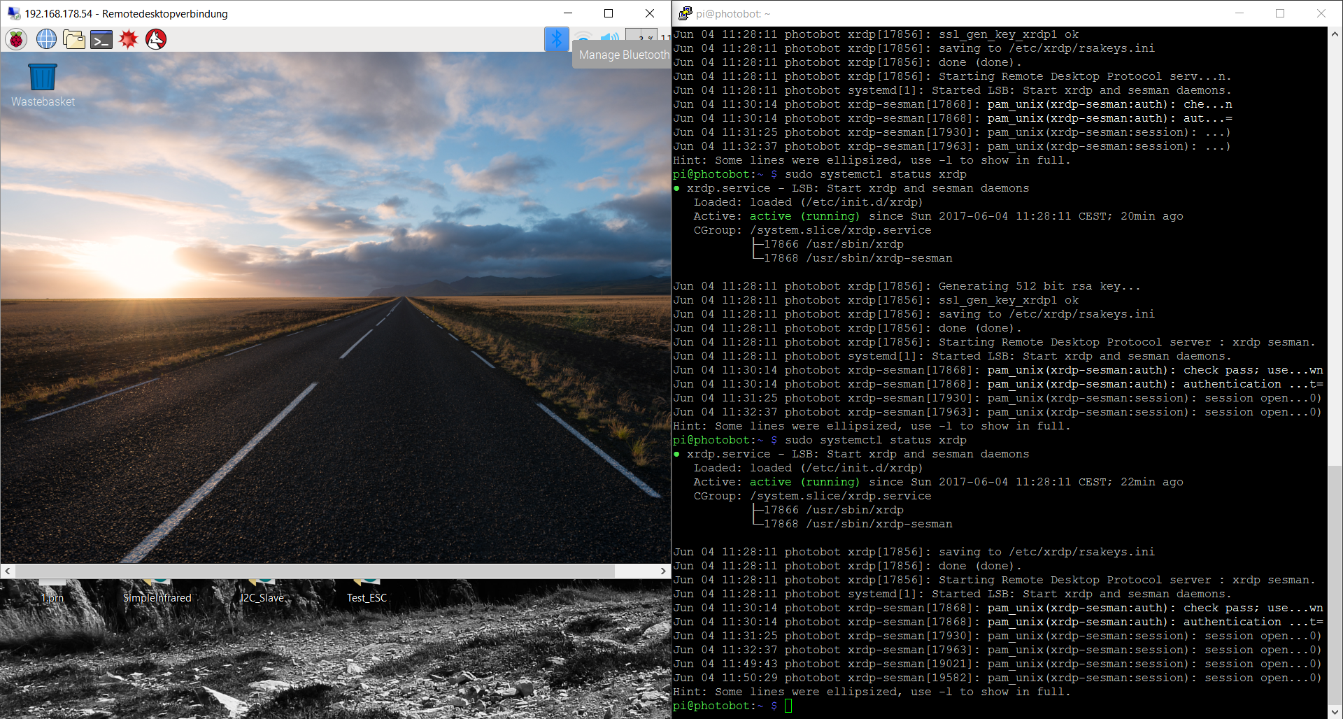
Next step, setup remote desktop. This is rather optional. Type sudo apt-get install xrdp to enable it.
To check the status:
sudo systemctl status xrdp
This may take a few minutes. If you get an error message, try this:
$ sudo apt-get install tightvncserve
On my Windows machine, I used the remote control application, typed in the IP address and connected.
The most suitable way of sharing files with the pi remotely seems to be a samba file server. Here is how it is set up.
sudo apt-get update
sudo apt-get install samba samba-common smbclient
After the installation, check whether the following processes are running:
sudo service smbd status
sudo service nmbd status
The standard configuration file is very exhaustive, so we create a new one for a simple basic configuration:
sudo mv /etc/samba/smb.conf /etc/samba/smb.conf_old
sudo nano /etc/samba/smb.conf
Use this code to paste into the smb.conf:
[global]
workgroup = WORKGROUP
security = user
encrypt passwords = yes

[SambaTest]
comment = Samba-Test-Freigabe
path = /home/shares/test
read only = no
browsable = yes
Use this command to confirm, that everything is working.
testparm
And restart the services...
sudo service smbd restart
sudo service nmbd restart
Create a home directory.
sudo mkdir /home/shares
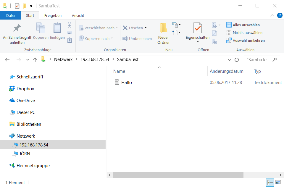
This directory will be seen as SambaTest on your Windows machine. chown (change owner) allows to change users or files. chmod 777 means everyone can read, write and execute. This is not advisible in general, but for a test it is OK.
sudo mkdir /home/shares/test
sudo chown root:root /home/shares/test/
sudo chmod 777 /home/shares/test/
For more information, check this.
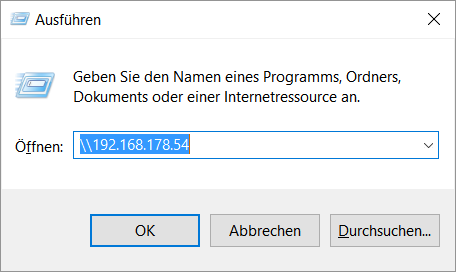
I typed run in the prompt on my Windows machine,
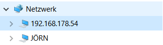
Login in with your credentials and find the folder created on the Pi.
Now let's continue and try to make the serial connection work.
Node JS
After testing Node JS on my Windows machine, making sure all control were working as expected, I started transferring the code the Pi. I installed Node JS on your Pi, following this tutorial. This does not work architectures below ARMv6, which is true for the Pi 2 & 3, but not for 1 & 0.
There is earlier Node version (4.2.4), built specifically for armv6l. Follow this tutorial to install it.
Another way of doing it, can be found here. I ended up using this.
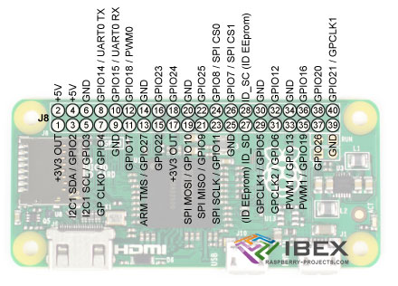
Then I connect the board to the Raspberry Pi Zero W, according to the pinout below. I connect GND, RX, TX and VIN.
I pushed the files Nodes JS files which I used for the networking assignment to the Raspberry Pi. I had to change the serial port to /dev/ttyAMA0, but it did not work. The USB port ttyUSB0 was fine, so I used an FTDI cable to connect the Pi and the board. Then, I changed the directory to home/shares/test/ and started the server typing:
node index.js
The server responded as expected.
Listening at: http://localhost:1337
Server is up
open serial communication
Request for / received
About to route a request for /
Request handler 'interface' was called.
Request for /favicon.ico received
About to route a request for /favicon.ico
user connected
Request for /favicon.ico received
About to route a request for /favicon.ico
Request for / received
About to route a request for /
Request handler 'interface' was called.
user connected
Request for /favicon.ico received
About to route a request for /favicon.ico
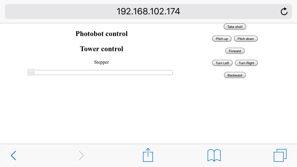
After typing the IP address of the Raspberry Pi (check ifconfig) and the port into your web browser, Node JS will respond with user connected. But it turned out that the port did not work. I switched to USB connection from the Raspberry Pi to serial of the Satshakit with an FTDI cable on port ttyUSB0.
The web interface showed up, the control worked.