Week 10 - Output devices
Menu
- Output devices
- Arduino prototyping
- Design & production of a modified Satshakit kit
- Programming Satshakit
- Download files
Output devices
Output devices basically turn an electrical input into any given output. It can be a visual ouput, e. g. a display, an audio output, e. g. a speaker or a mechanical output like a servo or motor.
For my final project, I will need servos, a stepper motor and at least two brushless DC (BLDC) motor. Therefore, I will try to combine this weeks task with the making of the electronics for my final project. I'm going to modify a Satshakit to hold the necessary components.
make video of ESC and embed
For here are the tasks for Week 10:
- Add an output device to a microcontroller board you've designed and program it to do something
- Document the process
Arduino prototyping
I will test all of the output devices of my final project upfront in an Arduino setup. This will contain, two servos, a stepper motor and two BLDC motors. I will go trough it one by one, before starting to design the actual Satshakit modifcation.
Stepper motors
My first output device will be a stepper motor. Stepper motor need additional hardware to be operated. These stepper motor drivers can either be build or bought. I will use a commercial Pololu stepper motor driver which I found here.
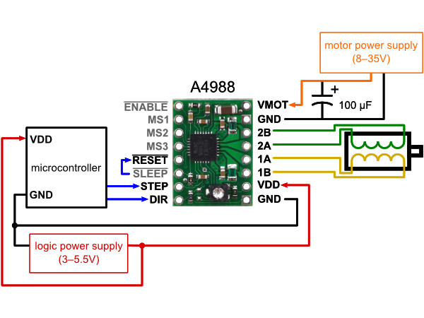
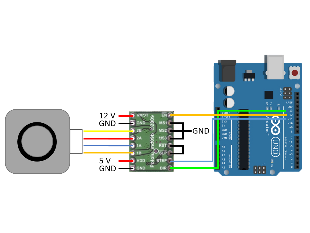
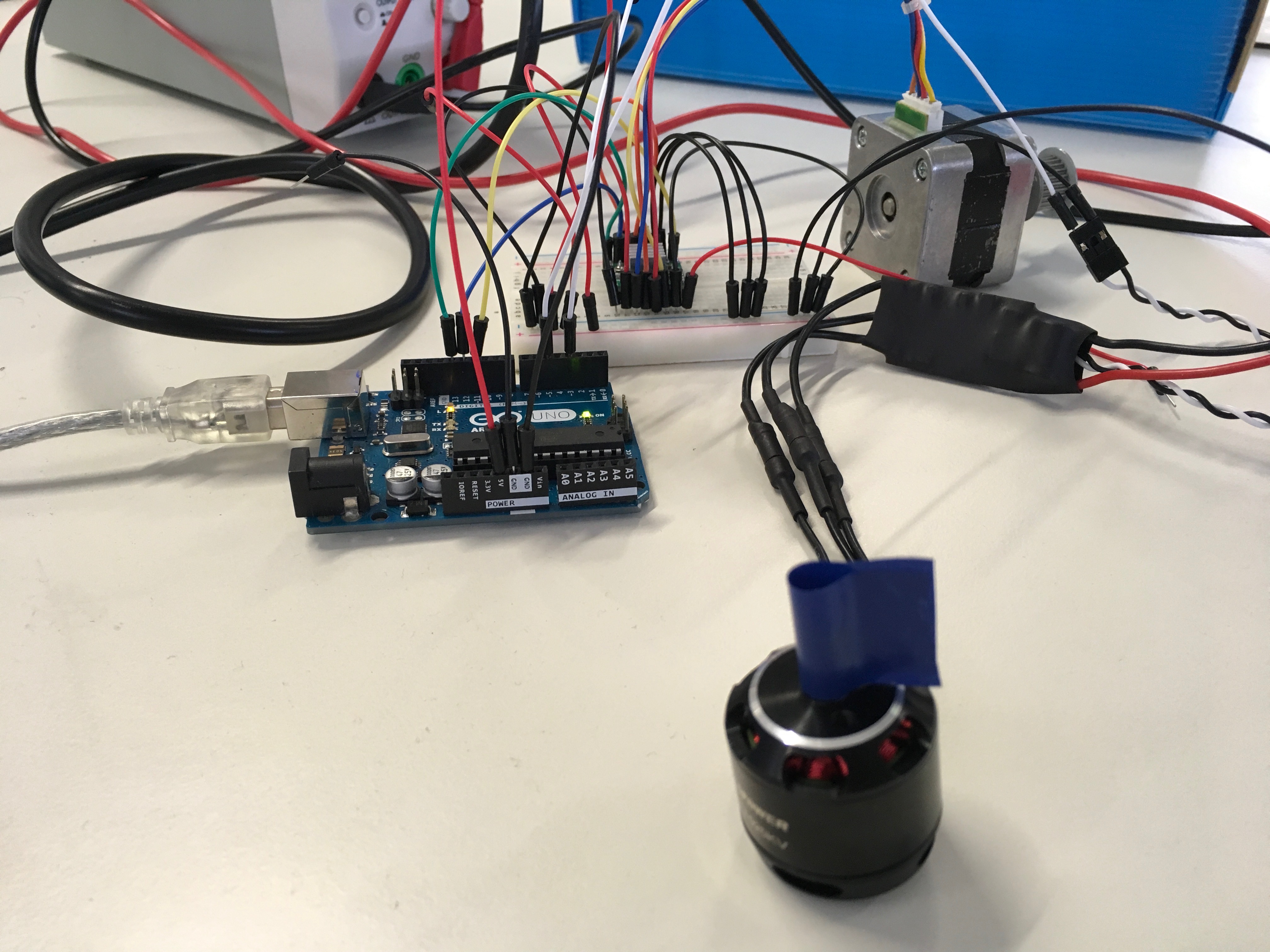
I connected my Arduino, the motor driver and the motor on a breadboard. The stepper motor driver needs a level of 5 V for basically three signals, which are ENABLE, STEP and DIR. The three pins marked MS control the step size. As I won't need high precision, I will go with full step size, connecting all pins to GND level. On the right hand side (left image), you can see the wiring for the motor. Coil 1 and 2 need to be connected accordingly. In my case, I selected a motor voltage VMOT of 12 V which comes from an external power supply. The final design will run on a 3S lipo battery which will me 11.1 V.
The motor is working with the sample code which runs on the Arduino. However, it took some tweaking of the waiting time. If it is not set correctly, the motor will only buzz but not move a step. I set the wait variable to 500 which worked fine.
Sample code for stepper motor:
// Control of a stepper motor

int enablePin = 12;
int dirPin = 13;
int clkPin = 11;
int wait, waitWhileSwitch;
int received;
int timeToSwitch = 1000;
int counter;
bool dirStatus;

void setup()
{
  Serial.begin(115200);
  pinMode(enablePin,OUTPUT);
  pinMode(dirPin,OUTPUT);
  pinMode(clkPin,OUTPUT);
  digitalWrite(enablePin,LOW);
  digitalWrite(dirPin,LOW);
  wait = 500;
  waitWhileSwitch = 1000;
  counter = 0;
  dirStatus = false;
 }

void loop()
{

  while(Serial.available() > 0){
    received = Serial.parseInt();
    if(received != 0){
      wait = received;
       Serial.println(wait);
    }

  }  ++counter;

 if(counter > timeToSwitch){
  counter = 0;
  if(!dirStatus){
    dirStatus = true;
         delay(waitWhileSwitch);
         digitalWrite(dirPin,HIGH);
  }
  else{
      dirStatus = false;
         delay(waitWhileSwitch);
         digitalWrite(dirPin,LOW);
     }
 }

 digitalWrite(clkPin,LOW);
 delayMicroseconds(wait);
 digitalWrite(clkPin,HIGH);
 delayMicroseconds(wait);

 digitalWrite(clkPin,LOW);
 delayMicroseconds(wait);
 digitalWrite(clkPin,HIGH);
 delayMicroseconds(wait);
}
Here is how it works:
Brushless DC motor
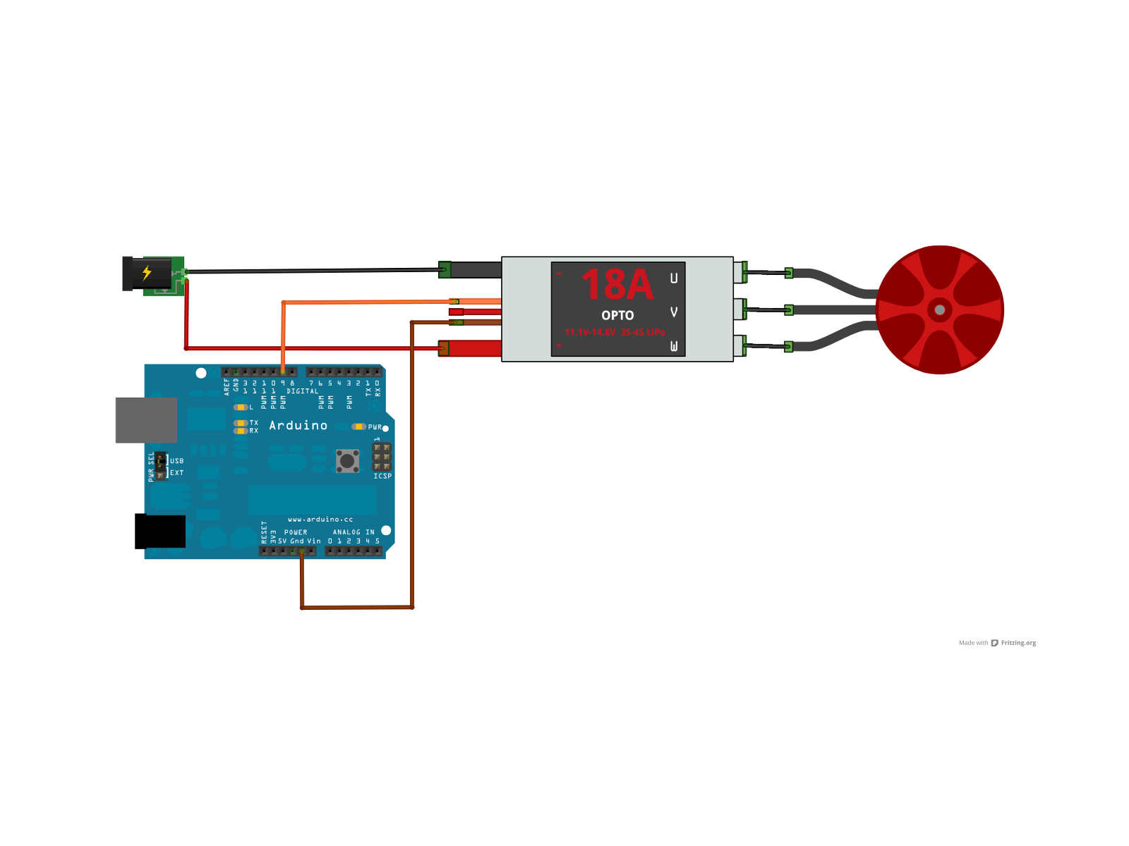
My next output device is the brushless DC (BLDC) motor. For a BLDC motor, there wiring is rather easy. As building my own power electronics however is rather complex, I will rely on "off the shelf" components from a commercial vendor. The electronic speed controller (ESC) needs the GND level as well as a PWM signal generated by the microcontroller. For testing, I'm using an 20 A ESC with no BEC (battery eliminator circuit). ESC containing BECs can also be used to power components with lower voltage (basically containing step down elements), which is the common way for 5 V receivers of a radio controlled plane or drones. I will probably do so in my final design but in this case, I will power the Arduino from USB, the ESC for the BLDC motor will get its power from the external supply at 12 V. I used the following code to control the motor, applying serial commands to control the speed.
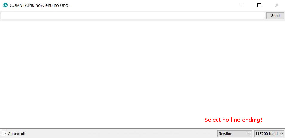
If you are using the serial monitor to control the speed of the motor, make sure to select No line ending in the dropdown menu. Otherwise, you will waste hours of trying to figure out what is wrong with the code or the serial library or your Arduino board.
Here is how I wired everything.
I used this code to test control of an ESC-powered BLDC motor.
// Control of a esc bldc motor

#include <Servo.h>

Servo esc;
int speedValue =100;    // defined variable

void setup() {
  Serial.begin(115200);   // pinMode(5,OUTPUT);
  esc.attach(5,1000,2000);
  esc.write(5);
  delay(500);
  esc.write(20);
  esc.writeMicroseconds(1000);
  speedValue =1000;
  delay(1000);
}

void loop() {
  while(Serial.available()>0){   // if some data come to the serial it will be passed to the speedValue
    speedValue = Serial.parseInt();   // here the read-in values get assigned to the variable speedValue
  }
  esc.writeMicroseconds(speedValue);  // here the values will be writen to the ESC
}
Here is how it works:
Servo testing
The servo motor will also be controlled by the microcontroller. Just like the ESC, these are controlled by a PWM signal at 5 V. Furthermore, GND and VCC are needed. The 3-Pin-socket is a common connector in RC vehicles. My modified Satshakit design will also have some of these sockets, using BEC ESCs to step down the battery voltage to 5 V to power the Satshakit and the servos.
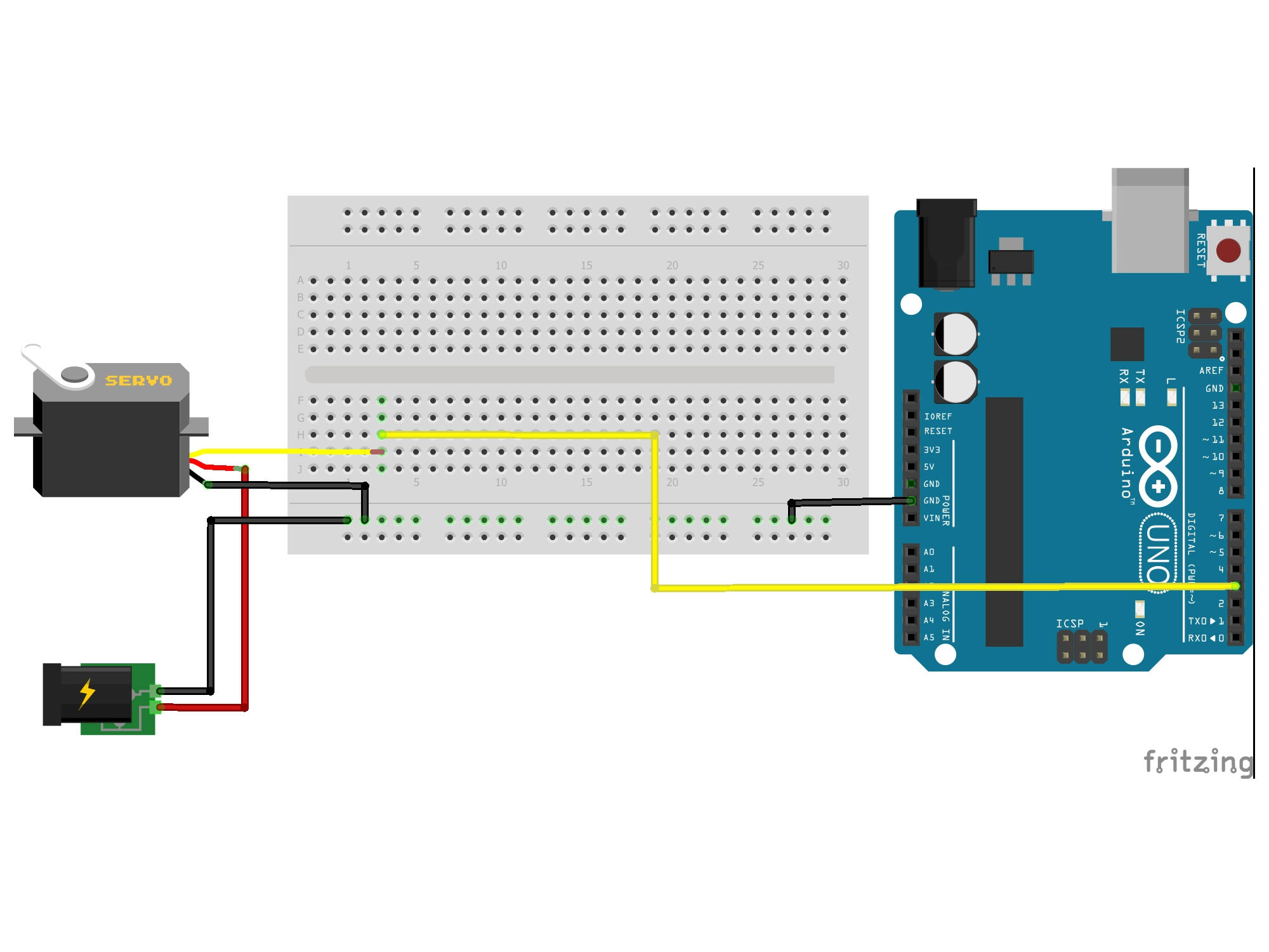
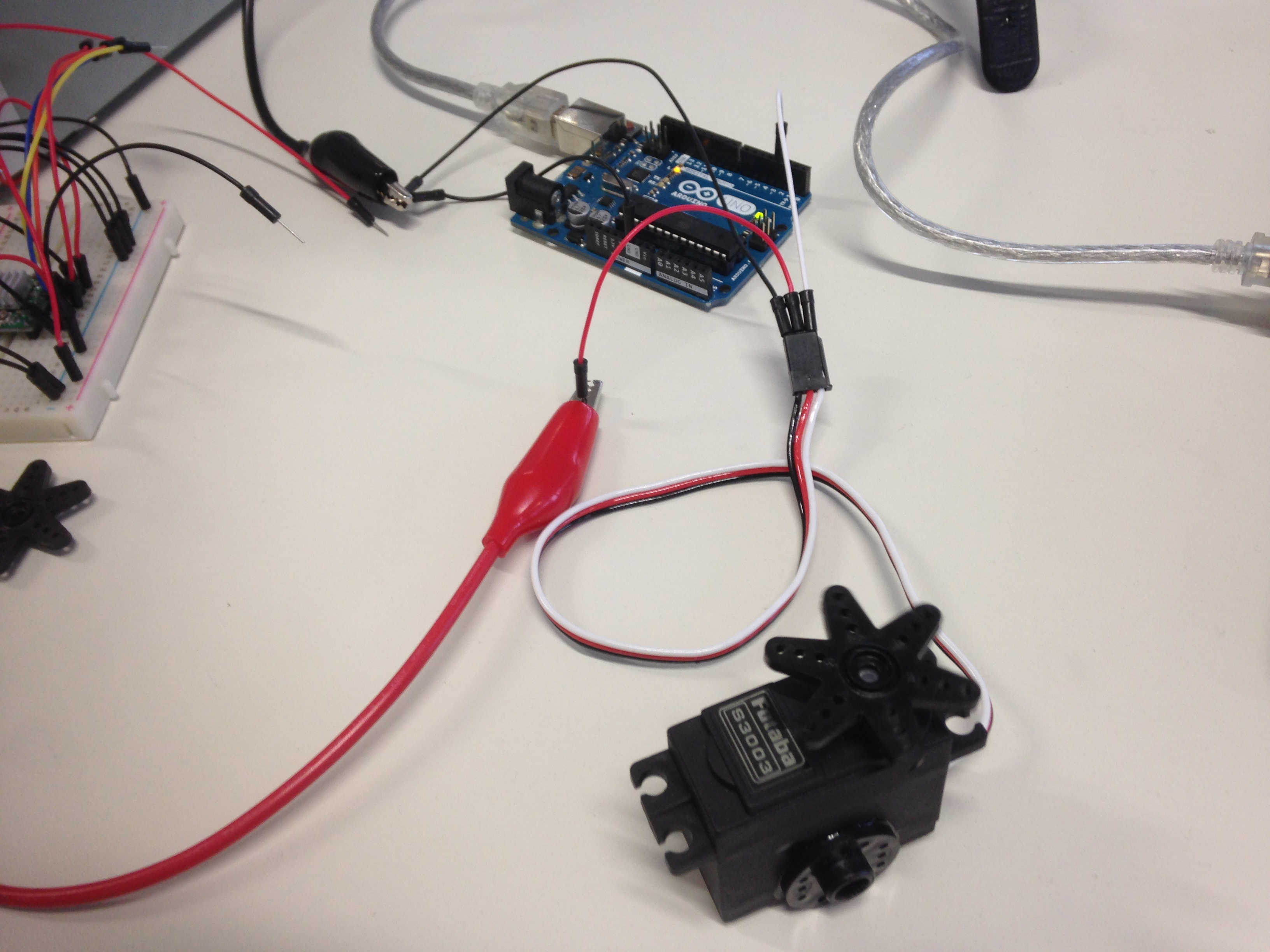
Here is the code to control the servos. I used a demo code from the Arduino examples. Two of servos I tried to move were broken which also cost me some time to figure out. The third one however started moving. I also controlled the servo with serial command. It worked but the servo was rather shaky after reaching its final position. This maybe caused by noise on the PWM signal.
1. Hello world sketch for the servo:
// Controll of a servo

#include <Servo.h>

Servo myservo;  // create servo object to control a servo
// twelve servo objects can be created on most boards

int pos = 0;    // variable to store the servo position

void setup() {
  myservo.attach(3);  // attaches the servo on pin 9 to the servo object
}

void loop() {
  for (pos = 0; pos <= 180; pos += 1) { // goes from 0 degrees to 180 degrees
    // in steps of 1 degree
    myservo.write(pos);                 // tell servo to go to position in variable 'pos'
    delay(15);                          // waits 15ms for the servo to reach the position
  }
  for (pos = 180; pos >= 0; pos -= 1) { // goes from 180 degrees to 0 degrees
    myservo.write(pos);                 // tell servo to go to position in variable 'pos'
    delay(15);                          // waits 15ms for the servo to reach the position
  }
}
2. Servo control with serial commands:
// Controll of a servo

#include <Servo.h>

Servo ServoX;
int ServoAngle=0;    // defined variable

void setup() {
  Serial.begin(115200);   // pinMode(5,OUTPUT);
  ServoX.attach(3);
}

void loop() {
  while(Serial.available()>0){   // if some data come to the serial it will be passed to the speedValue
    ServoAngle = Serial.parseInt();   // here the read-in values get assigned to the variable speedValue
  }
  ServoX.write(ServoAngle);  // here the values will be writen to the ESC
  delay(15);
}
Here is how it works:
All components
Now, that I tested all components and their requirements, I will start with designing a modified Satshakit to control all of these components.
Design & production of a modified Satshakit kit
Satshakit modifications
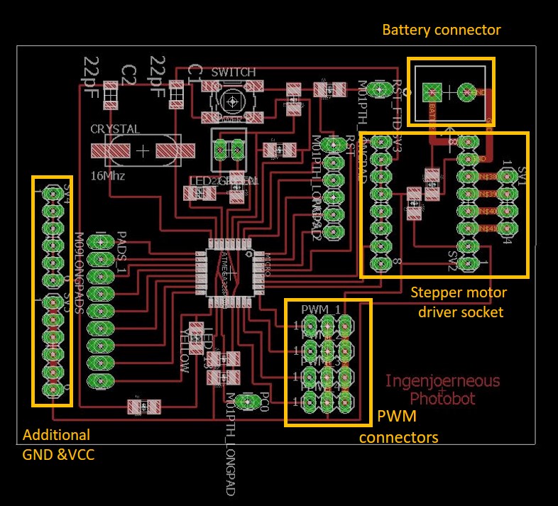
I started off from a Satshakit by adding:
- four PWM sockets for two servos as well as two ESCs
- a driver of a stepper motor (reconnected M14 Longpad pins)
- a socket for the battery connector (12 V)
- additional pins for that might need VCC as well as GND level (additional I/O devices.
The differences towards the original Satshakit can be seen in the comparison below.

In the schematics of Eagle, I rewired the the connections to the stepper motor driver as well as to the four PWM sockets. As two of the PWM sockets will carry BECs containing ESCs, they will be used to power the servos next to them. As the servos draw higher current, I increased the size of these traces as well. I added a link to a file containing the battery connector in the bill of materials below.
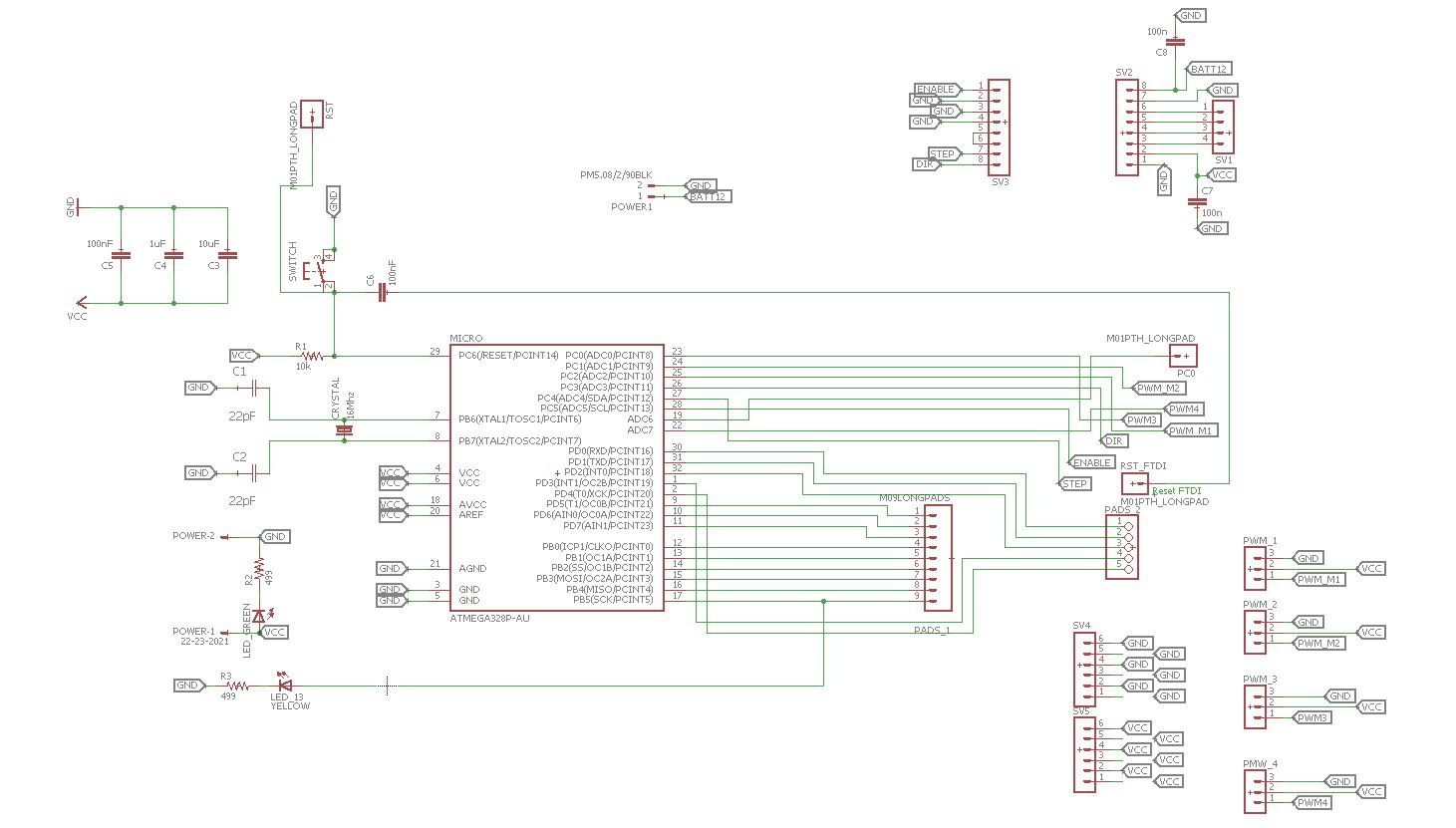
The former RESET pin which is circular was replaced by a oval one as these are easier to solder by hand. To account for the stepper motor driver, I wanted to create a socket on the Satshakit to hold the Pololu A4988 motor controller. I was inspired by a design from a former FabAcademy student.However, this design has the weakness of also using circular soldering pads, which is why I replaced the socket with female 8-pin headers. As the stepper motor needs 12 V supply voltage which will come directedly from the battery, the size of the traces was increased to 1 mm as well to account for high currents. The same is true for the wires that connect to the stepper motor (4-pin socket on the right hand side).
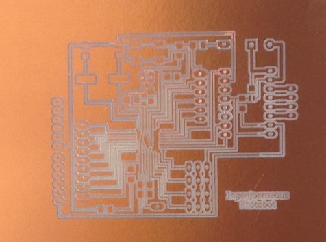
I followed the standard workflow described earlier to go from Eagle to GIMP to high resolution *.png images for the internal and the external tool paths. Having the two files creating, I went to production on the CNC mill - where the Odyssee began.


Production
It took me few trials to get the settings right for the PCB milling. An uneven bed caused several failures which can be seen in the failure alley below.
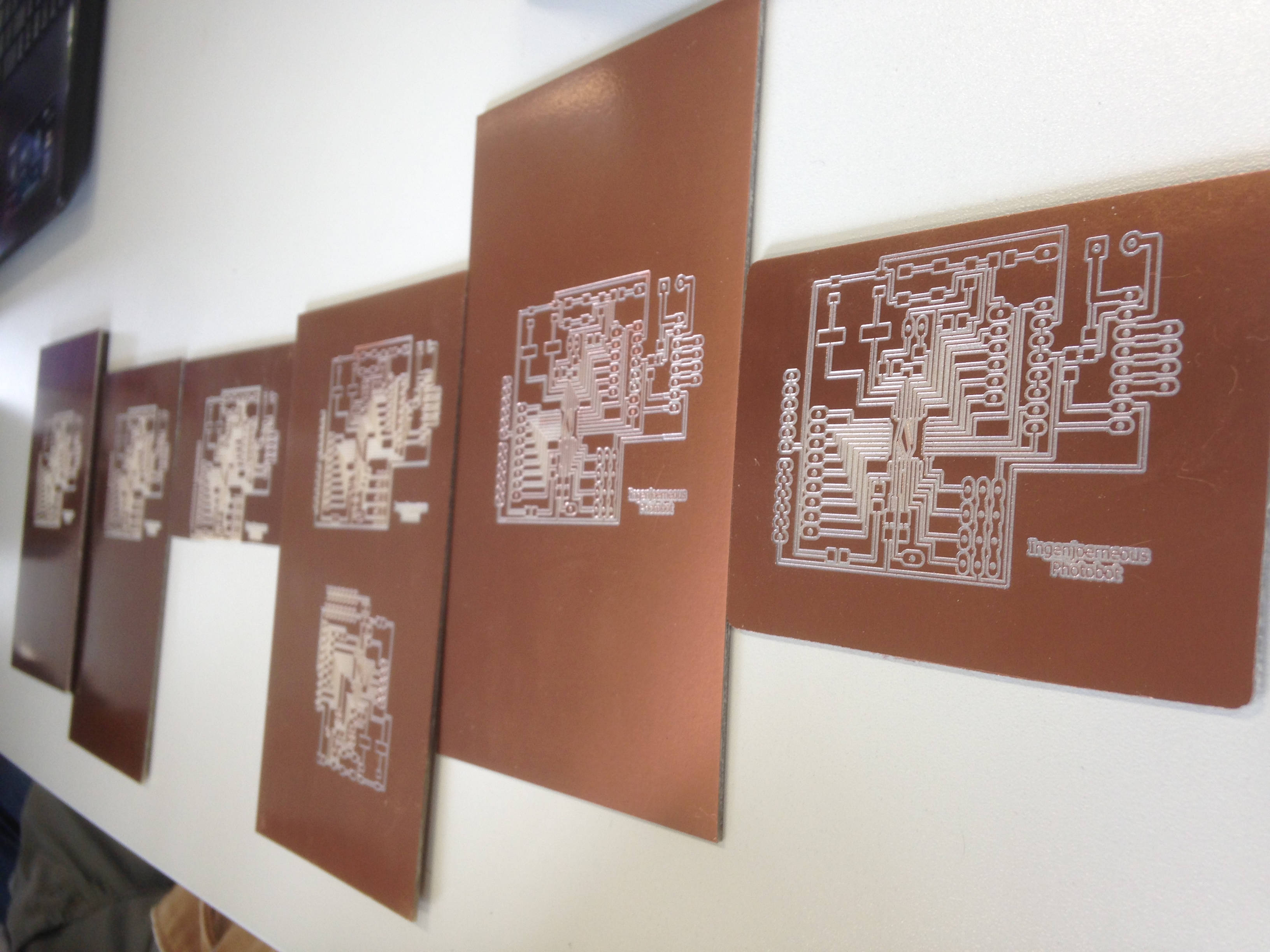
Here are some of the reason, why so many attempts to mill the board failed.
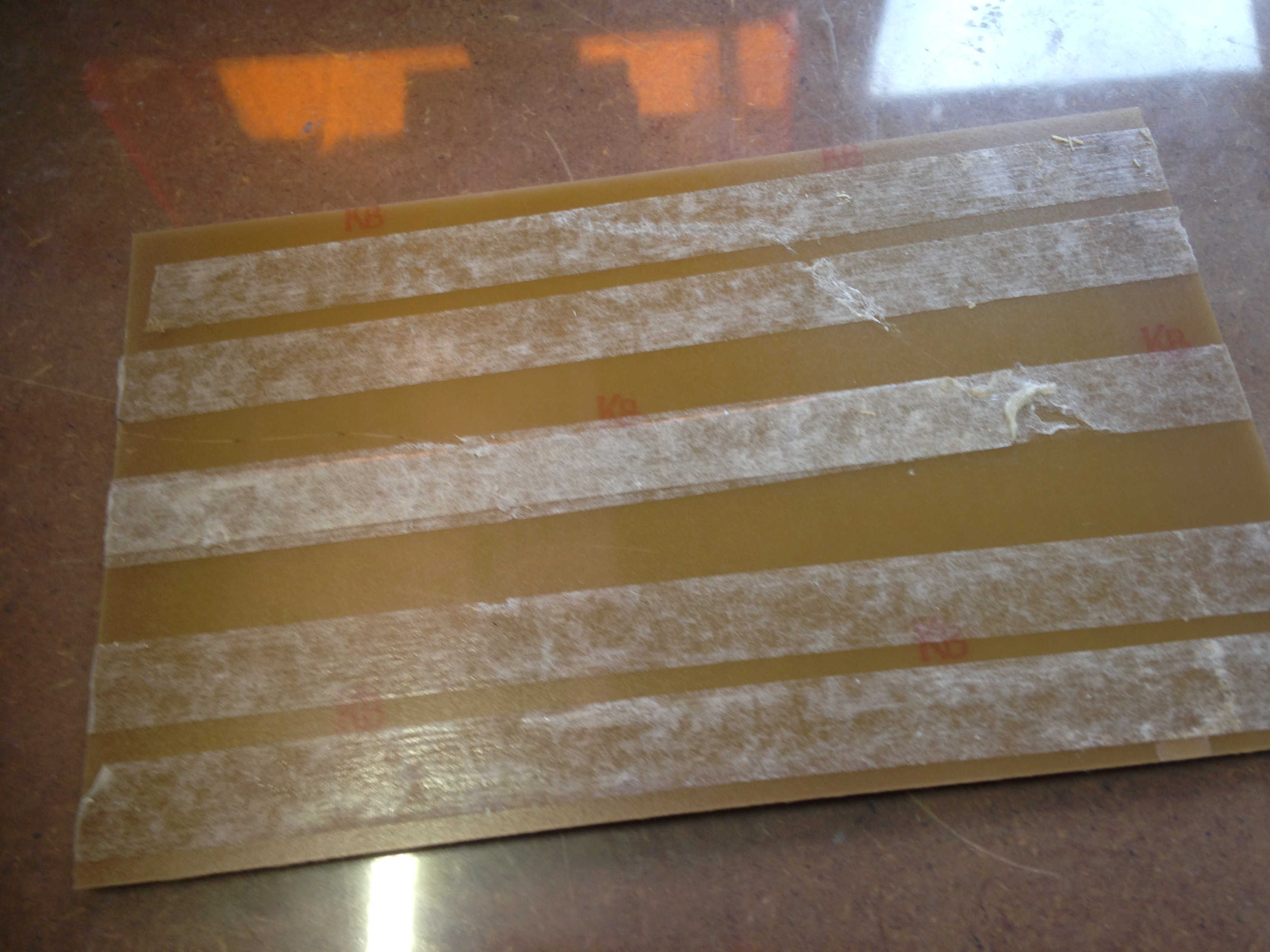
Cause 1 - I used the classical machine bed which is an MDF plate that carries the raw PCBs attached with double-sided tape. In this case, the bed was prepared poorly with two layers of tape in some regions causing unevenness.
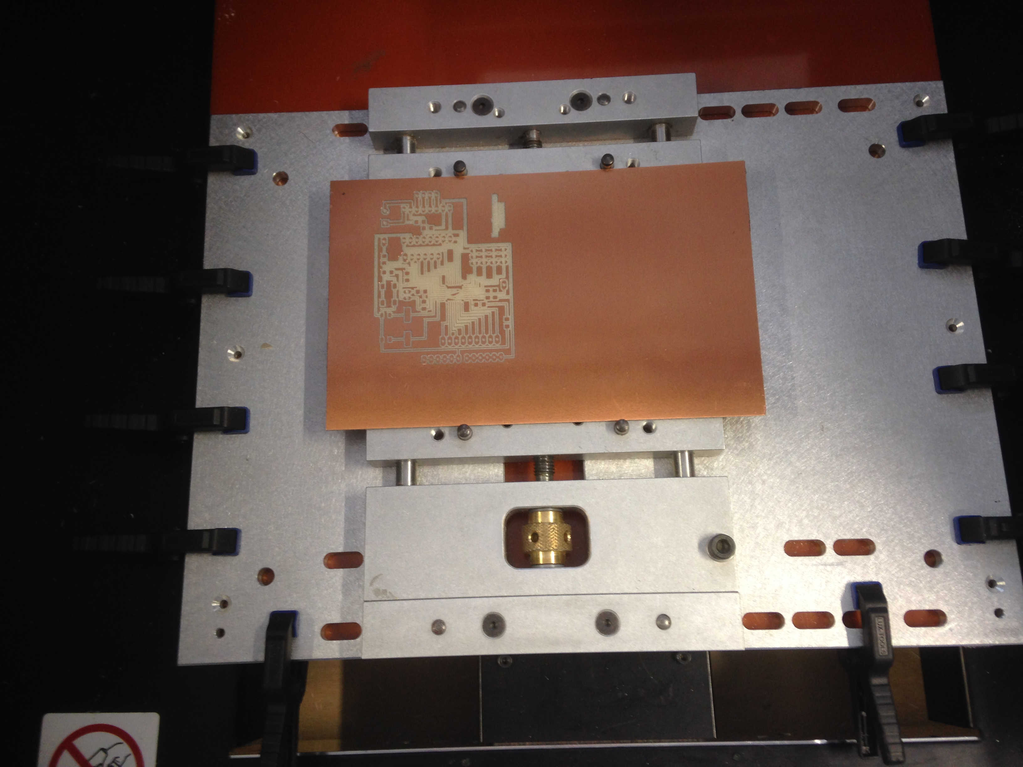
Cause 2 - After two more trials, we changed the bed using the one display here. A sacrificial layer would need to added for the cutting part, so I support the PCB to be engraved with another PCB. I tightening it too much so a bending occured. Then, I lasercut a MDF plate with the size of the PCB plate in order avoid bending which then resulted in uneven surface again. Traces turned out to be ok, other were not well enough insulated. I modified the internal engraving in GIMP and cut the traces again.
The result were traces that were very nice in the middle of the board but to thin on the other sections. I modified the *.pngcode> image for the internal path and milled again.

The result was still not fully satisfactory plus some traces cut and would have to be resoldered by hand. Furthermore, the loose tightened brackets caused the PCB come fall out during vacuum cleaning the traces after the internal cut. This caused loss of the origin point, so I had to engrave another one.
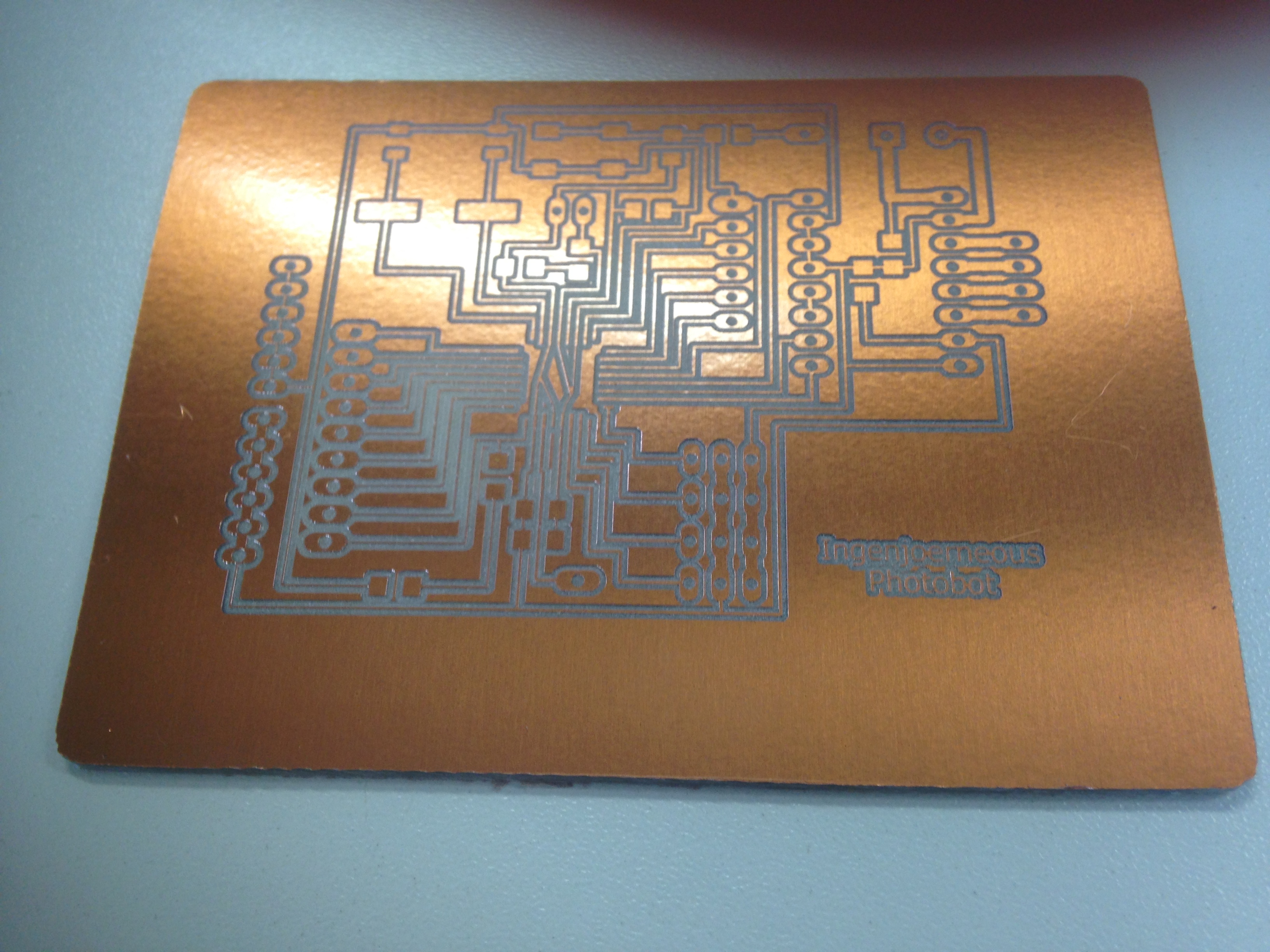
The final solution was a smooth tightening of the PCB as well as the use of another "sacrificial" PCB underneath it. Here are the settings, I used:

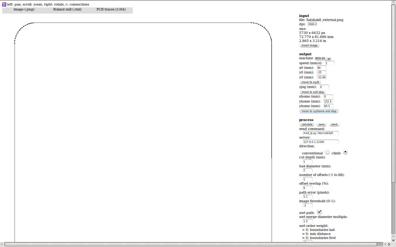
In the end, three offsets turned out to be sufficient, leaving me with very nice final result.
Soldering
Most of the components are identical with the original Satshakit:
- Capacitors: 1 uF, 10 uF, 2x 22 pF, 5x100 nF
- Crystal: 16 MHz
- Resistors: 2x 500 Ohm, 10 kOhm,
- LED: green, yellow,
- Microcontroller: ATMEGA328P
- Switch: 6 mm
- Connectors: male
- (NEW*)Power connector: PM5.08/2/90 BLK (Eagle component)
- (NEW*)Connectors: female
Programming Satshakit
To jump start the ATMEGA328, an Arduino (or another microcontroller or a FabISP) is required to install the bootloader. Afterwards, you can switch to programming via FTDI which does not require any additional microcontroller. I will check if everything works as expected by flashing a blink sketch. Finally, I will test the control of a BLDC motor which is one the output device I studied.
Burning bootloader
Burning the bootloader require the already known, MISO, MOSI, CLK, VCC, GND and RESET connections. I installed the Arduino ISP sketch on an Arduino Uno as done before.
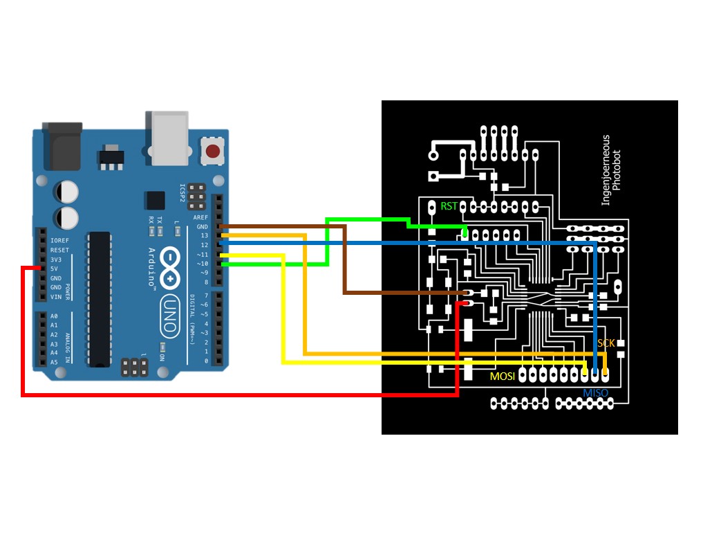
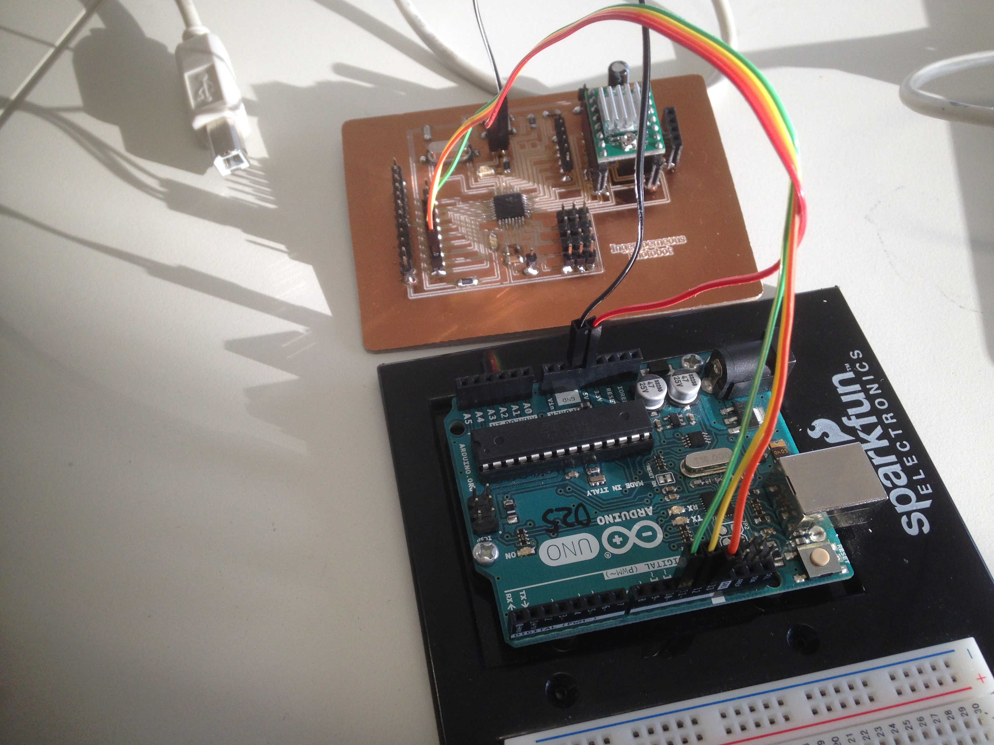
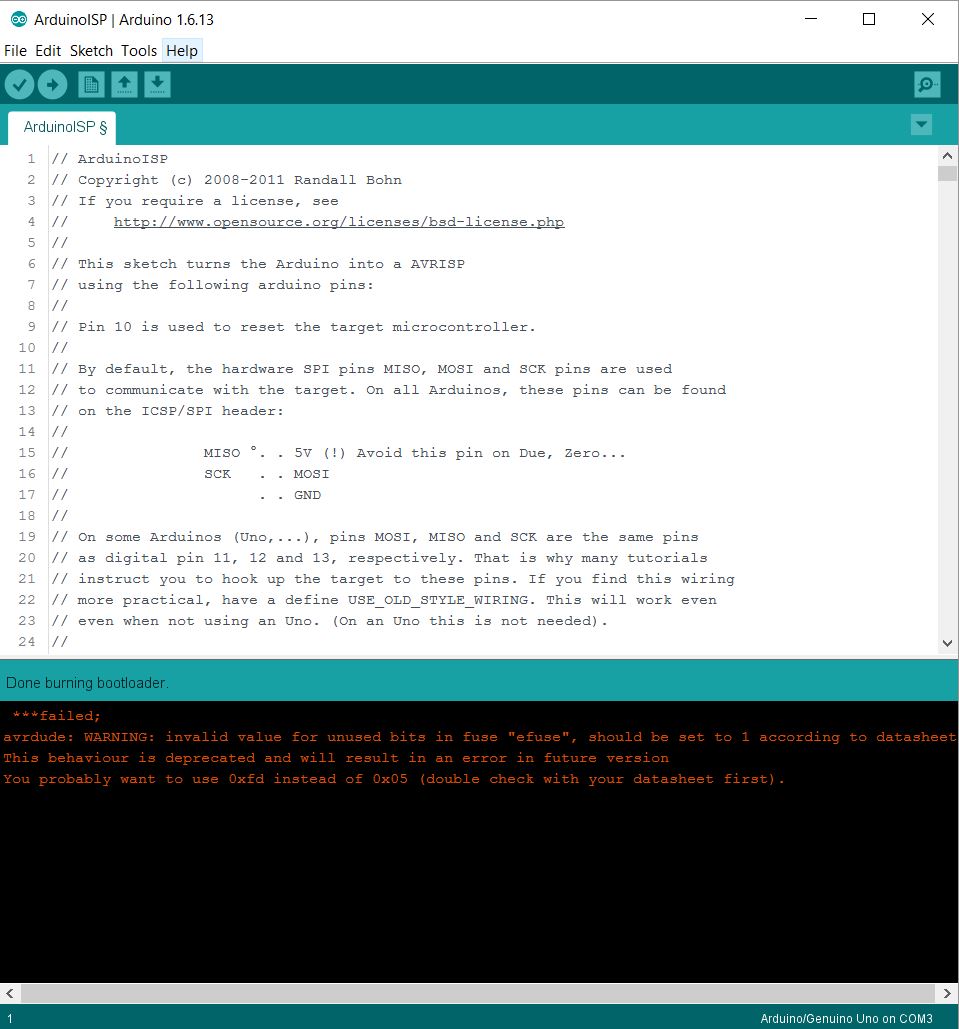
Select tools and click burn bootloader. The Arduino confirmed the successful installation of the bootloader though returning a warning, which could be ignored.
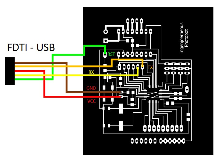
FTDI connection
Now that the chip is equipped with a bootloader, it switched to FTDI connection for programming. Please find the wiring below.
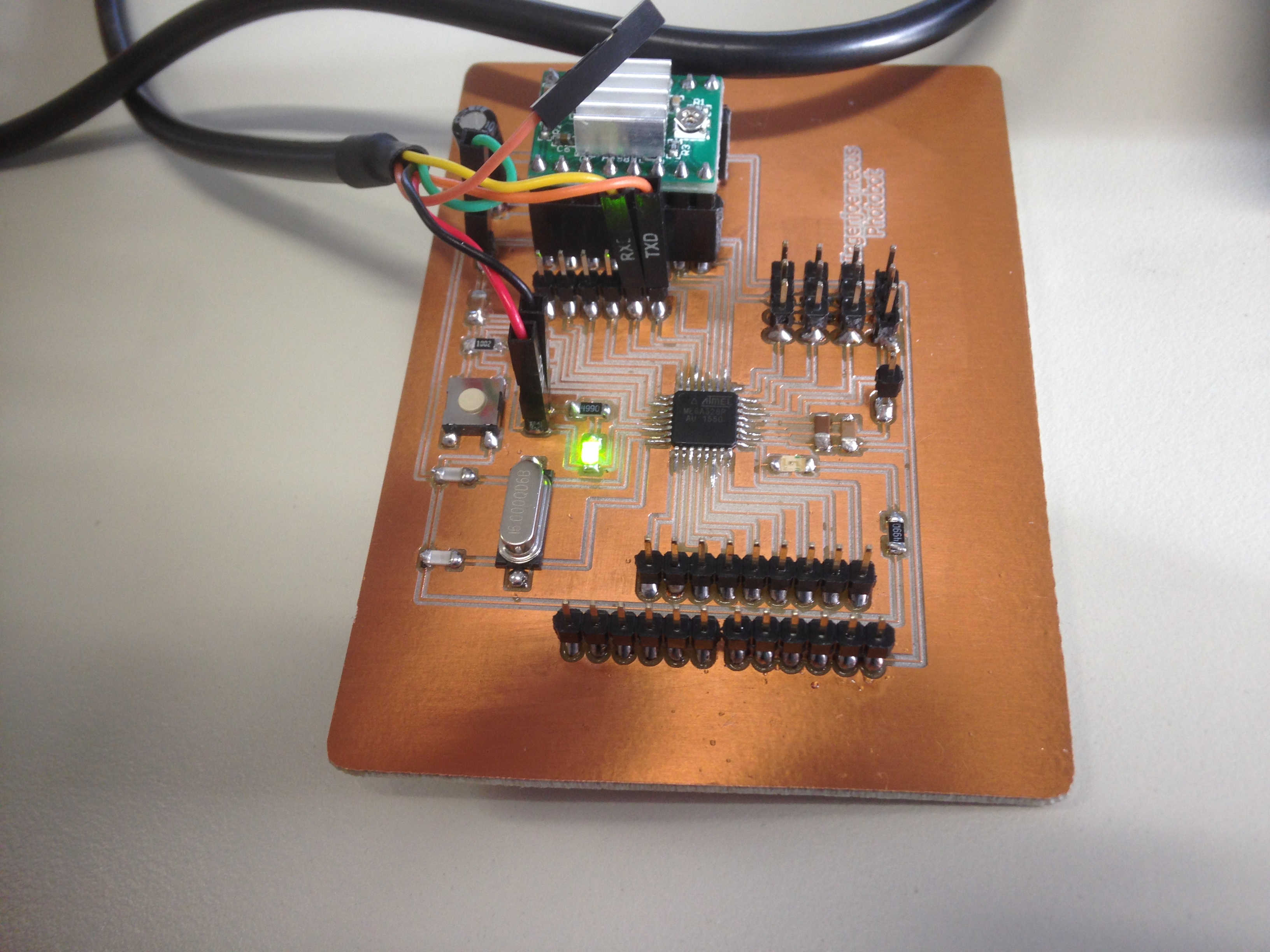
Blink sketch
I installed a blink sketch to confirm that the chip was not damaged during the soldering process. As I was using the Arduino IDE, I had to find the right pin translation.
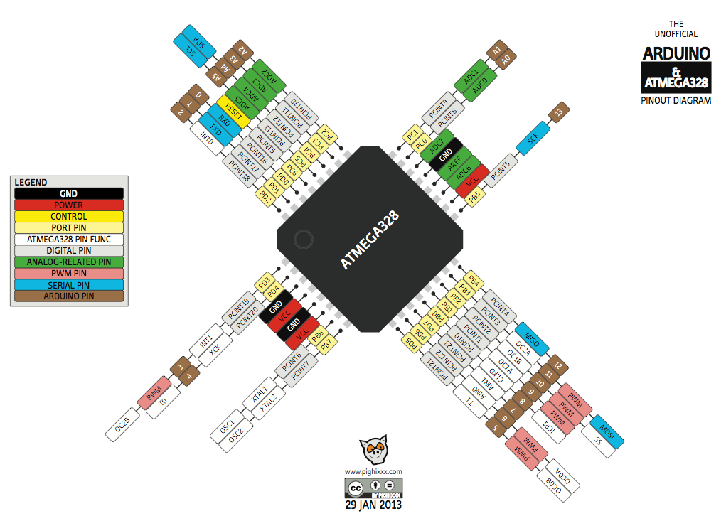
Below, you can find Blink sketch for the Satshakit, the LED is connected to PB5 which is'Arduino' pin 13 according to the legend.
int LED_PIN=13;

// the setup function runs once when you press reset or power the board
void setup() {
  // initialize digital pin LED_BUILTIN as an output.
  pinMode(LED_PIN, OUTPUT);
}

// the loop function runs over and over again forever
void loop() {
  digitalWrite(LED_PIN, HIGH);   // turn the LED on (HIGH is the voltage level)
  delay(1000);                       // wait for a second
  digitalWrite(LED_PIN, LOW);    // turn the LED off by making the voltage LOW
  delay(1000);                       // wait for a second
}
If I did everything correctly...it works!
ESC sketch
I controlled a BLDC motor with the modified Satshakit which concludes this week's tasks. I'm using the VarSpeedServo library and a short initialization sequence in the setup function. The motor's ESC is connected to A1 which sends the PWM signal.
#include <VarSpeedServo.h>

VarSpeedServo esc;

void setup(){
  pinMode(A1,OUTPUT);
  esc.attach(A1,700,2000);
  esc.write(5);
  delay(500);
  esc.write(20);
  esc.writeMicroseconds(1000);
  delay(1000);
}
void loop() {
  esc.writeMicroseconds(1300);
}
The code works as expected.
Stepper motor sketch
Finally, I tested the stepper motor with the Pololu stepper motor driver. I did so on a bread board first and adding it to the socket on the Satshakit in a second step.

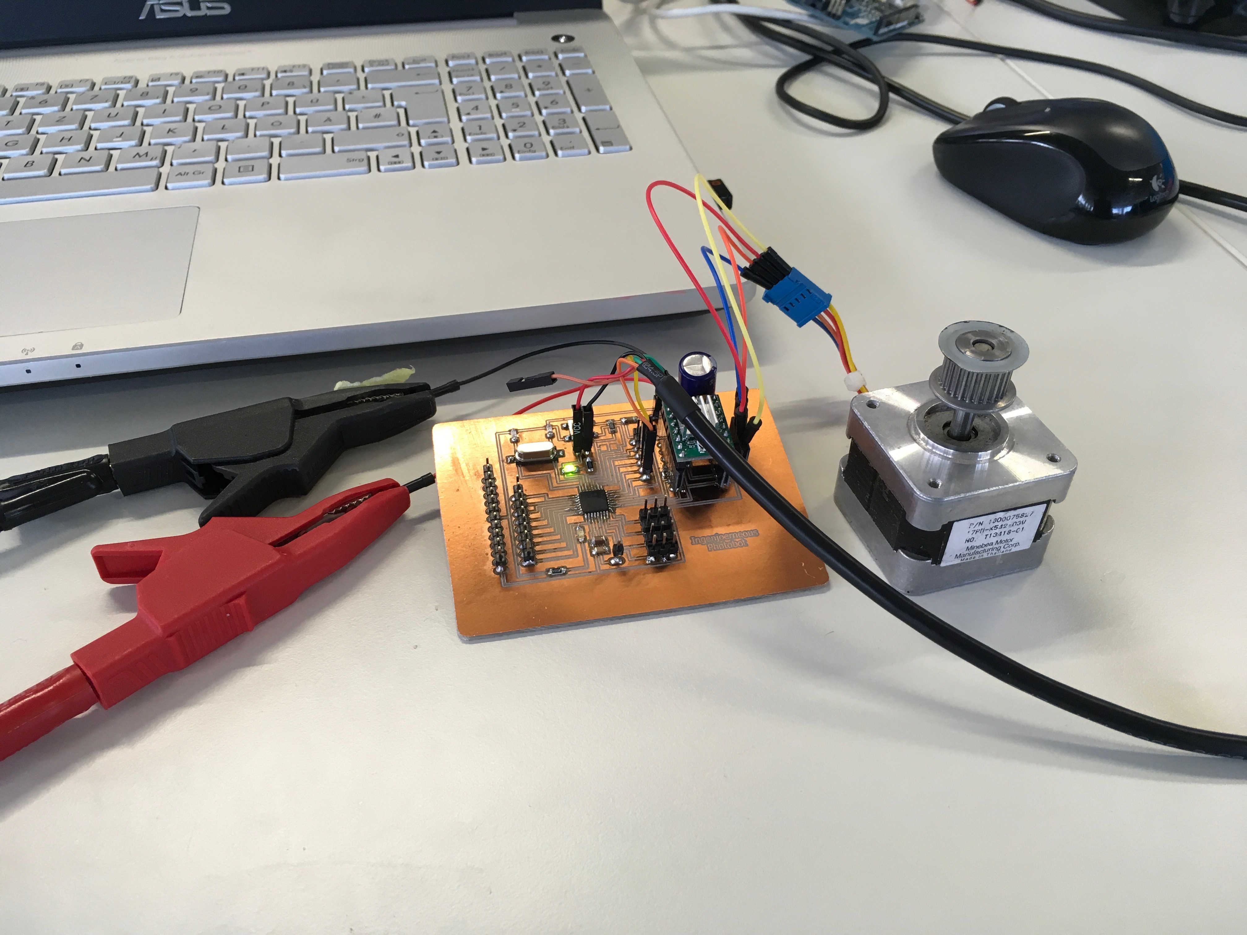
I changed the enablePin, dirPin and the clkPin according to the connection on the Satshakit.
int enablePin = A5;
int dirPin = A3;
int clkPin = A4;
int received;
int timeToSwitch = 1000;
int wait = 1000;
int waitWhileSwitch = 1000;
int counter;
bool dirStatus;

void setup()
{
  Serial.begin(115200);
  pinMode(enablePin,OUTPUT);
  pinMode(dirPin,OUTPUT);
  pinMode(clkPin,OUTPUT);
  digitalWrite(enablePin,LOW);
  digitalWrite(dirPin,LOW);

  counter = 0;
  dirStatus = false;
 }

void loop()
{

  while(Serial.available() > 0){
    received = Serial.parseInt();
    if(received != 0){
      wait = received;
       Serial.println(wait);
    }

 }  ++counter;

 if(counter > timeToSwitch){
  counter = 0;
  if(!dirStatus){
    dirStatus = true;
         delay(waitWhileSwitch);
         digitalWrite(dirPin,HIGH);
     }
     else{
      dirStatus = false;
         delay(waitWhileSwitch);
         digitalWrite(dirPin,LOW);
     }
 }

 digitalWrite(clkPin,LOW);
 delayMicroseconds(wait);
 digitalWrite(clkPin,HIGH);
 delayMicroseconds(wait);


  digitalWrite(clkPin,LOW);
 delayMicroseconds(wait);
 digitalWrite(clkPin,HIGH);
 delayMicroseconds(wait);
 }
It moves...I am so proud :)!
I will test the servos in the documentation for the final project.