
WEEK 19 (07 Jun 2017)
[Project Development]
The assignment for this week is to develop the FINAL PROJECT
The Idea
I have two cats (In the future a lot of small cats)
Siza (Male) and Zaha Hadid (Female)

And I need a smart food dispenser to follow my cat’s food consumption historical.
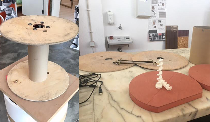
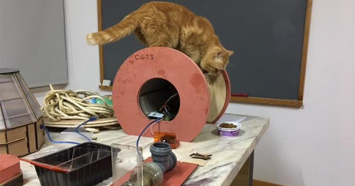
Automated Cat Feeder Is a smart food device "C.A.T'S ", which will dispense an amount of dry food at a chosen time of the day, is perfect for when I must leave my cats alone, and would rather that they don't starve, and one of the biggest difference for which there is already, is: this cat feeder was built based on recycling materials...(Garbage that I find in the construction works I'm going through).
Last minute proposal: it will also be a toy, on the rope they can sharpen the nails, and they love it...
Future improvements include:
Water dispenser...
List of some parts and components that I need to make this project:
Materials:
- Electric cable coil (recycled);
- 3D Printed a drill bit (Screw Mechanism)
- Plastic Tube (40mm Diameter x A little over a 0.26 Metre long) (recycled);
- Sheet of clear Acrylic (3mm and 5mm)
- Sheet of white and black Acrylic (3mm)
- White Wood MDF;
- Orange Valchromat;
- Wood Glue;
- Rope;
- Cork (recycled);
- Electric tube (recycled);
- Water tube (recycled);
- Cheese packaging (recycled);
- Vinyl Cutter; ( Cut the Logo C.A.T,S)
Electronics:
- Arduino (I need an Arduino UNO)
- Atmega 328P
- Continuous Servo (or a step Motor)
- 16x2 LCD Screen
- Potentiometer :
• Power Supply: 5V
• Produces analog output between 0 and Vcc on its D1 connector
• Resistance value: 10k ohms
- Power Supply (Anything above 500mA should have enough juice for the Servo and LCD):
• Plastic holder use for standard AA battery
• Number of cell: 6
• Double sided
- RTC - Real Time clock :
• Fully assembled and pre-programmed with the current time
• Lithium coin cell battery
• Run the module for a minimum of 9 years
• Accessed via the I2C protocol
- 1x3 Pin header for connecting servo motor
- 1x4 Pin header for connecting real-time clock (RTC)
- 1x16 Pin header for connecting LCD
- Numerous jumper cables
Plan and sketch my Final Project (Week 1)
Step 1: Required materials (Done)
Step 2: 3D Print drill bit (Screw Mechanism) (Done)
Step 3: Electronics :
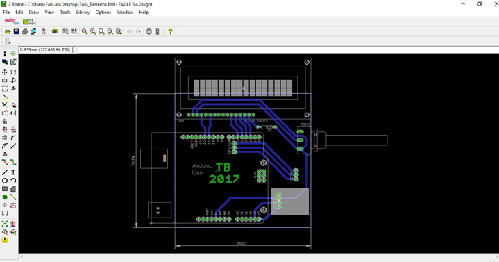
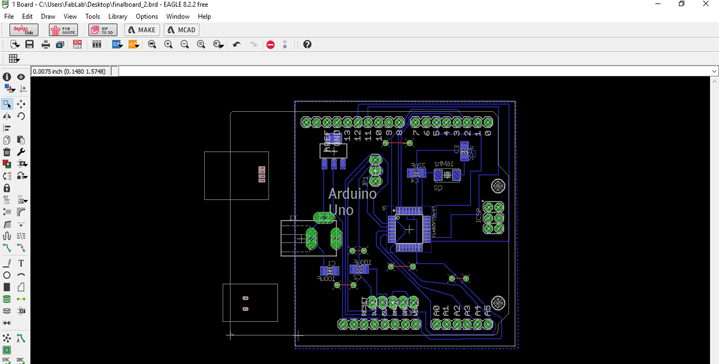
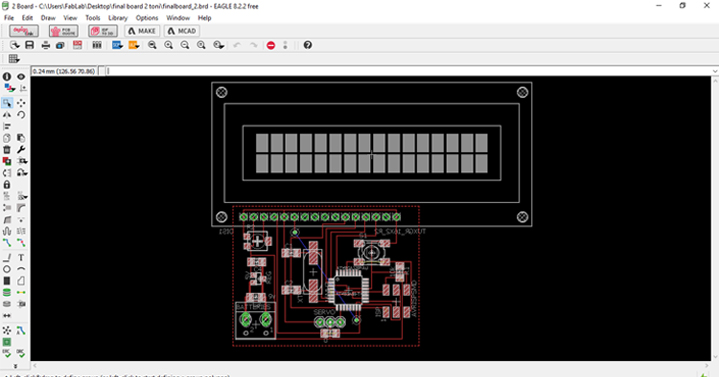
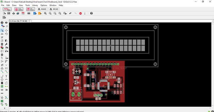
- 1st Phase - Drawing a first board on Eagle to work with the arduino (Done) :
- The board is a shield style for Arduino Uno, includes a RTC ds3231, is powered directly by the Arduino with 5v.
- It has a 100k potentiometer for contrast control of the 16x2 lcd and a resistance of 220Ohm to limit the supply current of the lcd background leds to about 15mA.
- The outputs will be pin Male and female headers that fit into the inputs of the Arduino and also for outputs to the servo motor and the RTC.
- The dimesion of the board is 8cm by 7.8cm
- The LCD will be connected through wires to the board for a more dynamic application.
- 2 st Phase Drawing a second board on Eagle with a microcontroller (Atmega 328P) made by me (Done):
In the 2 st phase, I made two boards one to be programmed with arduino, and the other one to be programmed with FabISP...
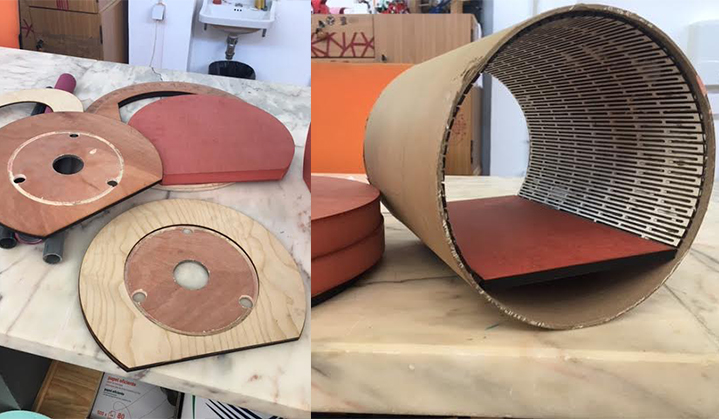
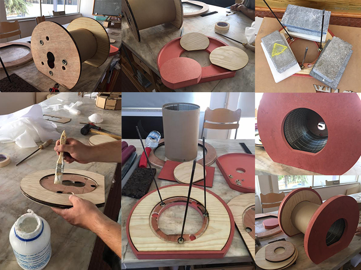
Step 4: Cutting the drawings in laser cut, and starting to assemble (Done)
Step 5: CNC ROUTER to cut the orange Valchromat (Done)
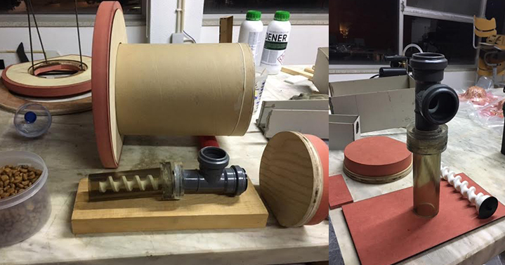
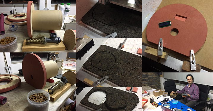
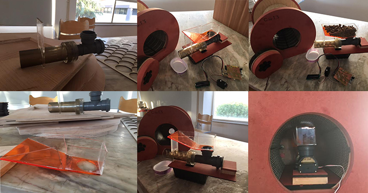
Step 6: Build a pipe with recycled materials and the inner funnel (Done)
Step 7: Programming (Done)
Step 8: Assembly of the recycled parts with the new parts (Done)
Step 9: Build the container for food in press-fit acrylic (Done)
Step 10: Vinyl Cutter and Finishing touches (Done)
Step 1:
Required Materials
Electronics:
1 x Arduino (We're using an Arduino UNO R3). Price - $24.95
1 x Atmega 328P - $2.14
1 x Continuous Servo (Can be bought or an ordinary Servo can be modified - Search Google). Price - $ 14.54
1 x 16x2 LCD Screen ic2. Price - $8.75
1 x Potentiometer. Price - $1.42
1 x Power Supply (Anything above 500mA should have enough juice for the Servo and LCD). Price - $1.24
1 x RTC. Price -$6.39
Total spending on electronics: $59.43
Step 2:
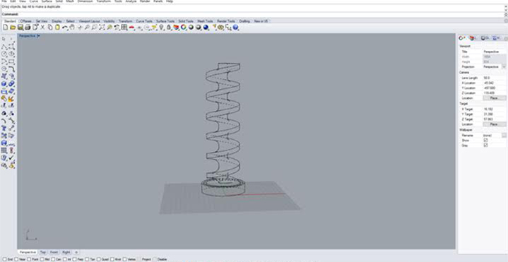
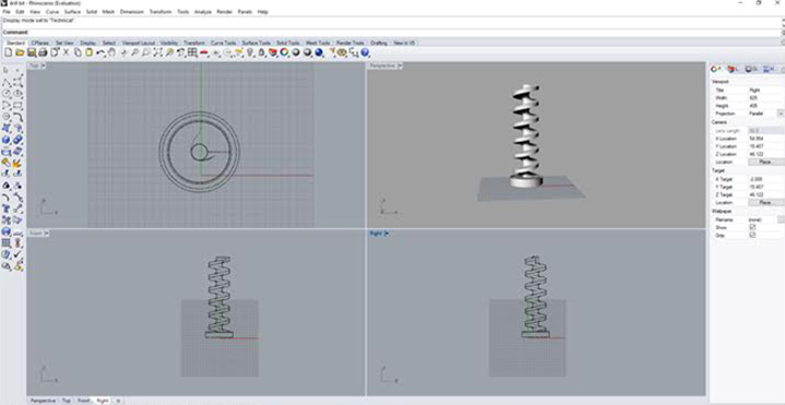
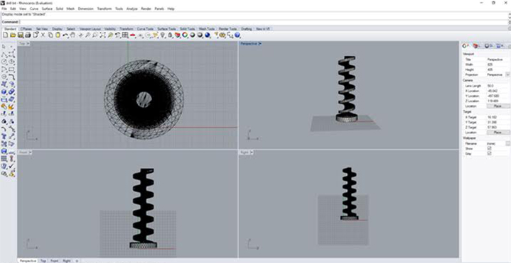
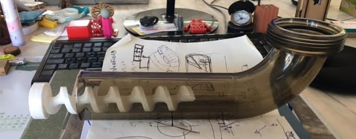
3D Print the Drill bit (Week 5)
One of the first things to do should be the main mechanism , it's by far the easiest part, because we have many 3D Printers in the Fab Lab. In the week 5 (the 3D scanning and printing assignment) I had already drawn the drill with Rhino, I just had to make some adjustments to improve the drill bit I also built a A funnel in 3D printer ( a pipe with a wide (often conical) mouth and a narrow stem. It is used to channel the food...
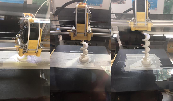
3D printer Funnel:
Watch the VIDEO:
Files:
- Files : Rhinoceros(drill bit .3dm) - drill bit.stl - 3D Funnel
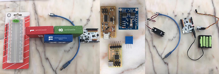
Step 3:
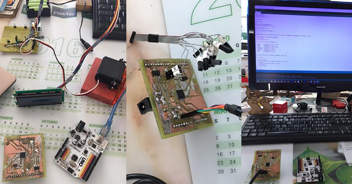
Electronics (Playing with electronics)
The next most important step of this project is the electronics, these are some of the components I need:
Schematic followed, it utilises all the components listed in Step 1:
Watch the VIDEO:
- Playing with electronics:
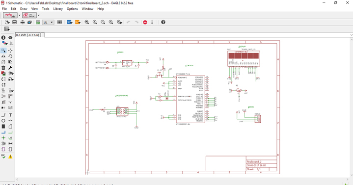
- 1 st Phase - Drawing a first board on Eagle to work with the arduino:
This is the schematic of my board:
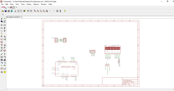
This is the board layout, and it shows how the electrical components and traces will be laid out on the board, and the dimensions of the board:
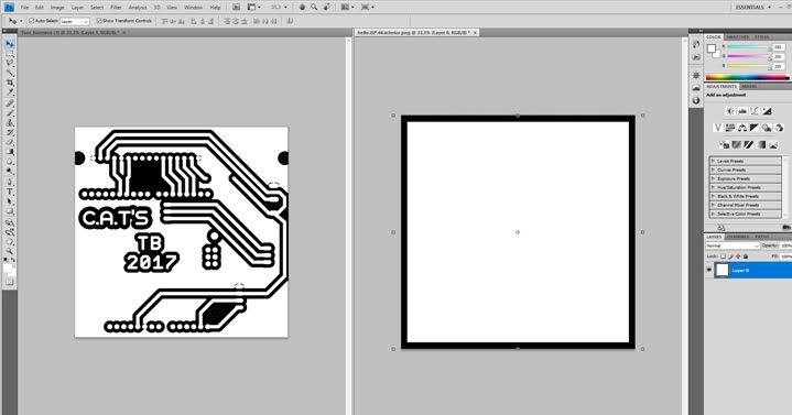
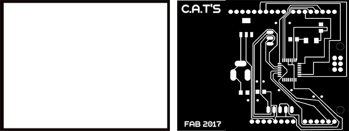
The Final Board PNG:
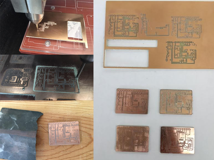
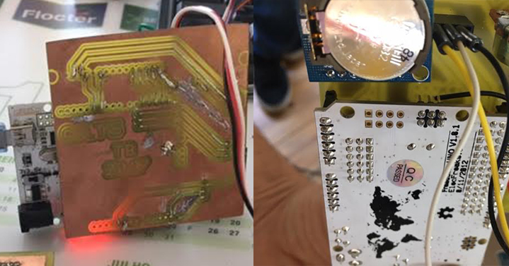
Milling the board:

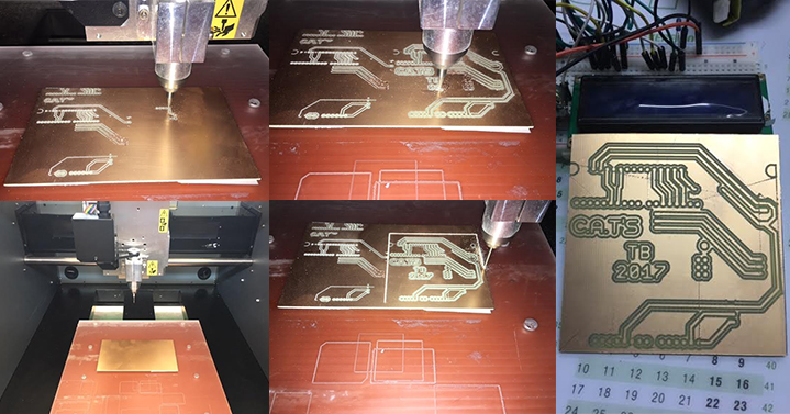
Final result:
Files:
- Files : Milling - Modela MDX 40
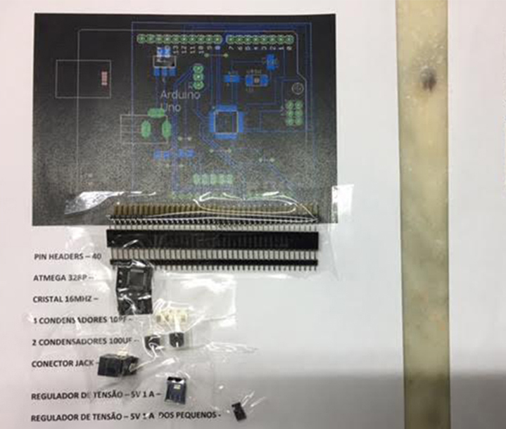
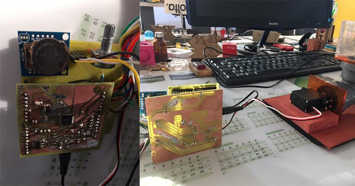
- 2 st phase - Drawing two more boards on Eagle with a microcontroller (Atmega 328P) one made by myself and thw other with the help of my remote instructor Luis Carvão :
THE COMPONENTS:
1 - Microcontroller: Atmega 328P
1 - Crystal
2 - 22PF AF Capacitors
2 - 100uf Capacitors
1 - Voltage Regulator
1 - Jack connector
43 - Pin Headers
Final Board 1 Schematic:
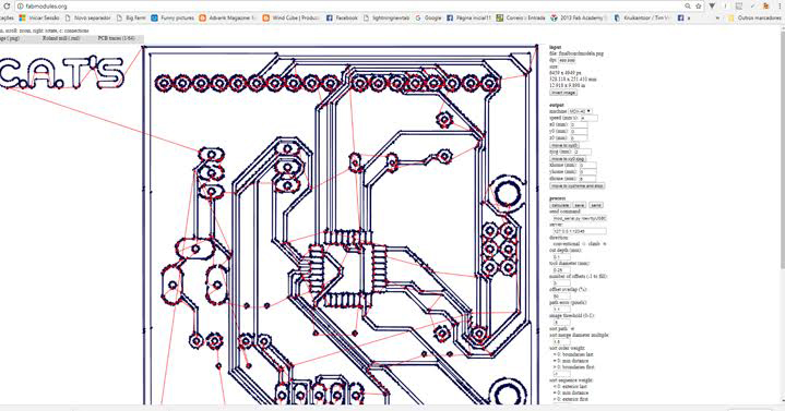
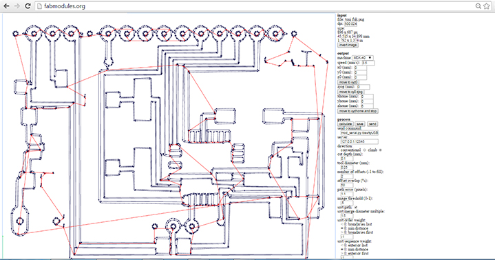
EXPORTING THE DESIGN & MILLING:
Once the design was finished and checked I exported PNG files of my new board:
- Selected through "LAYERS" option the appropriate layers to export;
- 500 dpi Resolution;
- MONOCHROME;
Generate the gcode. Using fabmodules website upload the .png files, select the process 1/64 for milling the traces and 1/32 to cut the outline. The steps are the same of WEEK 4 [Electronics Production]:
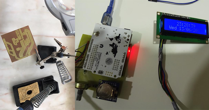
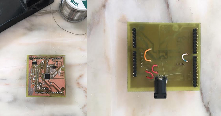
Verifying circuit, selecting the components and soldering: :
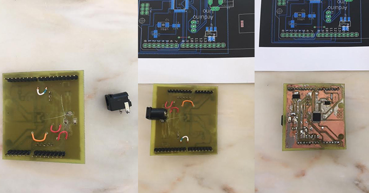
The Final Board 1 finished:
Final Board 2 Schematic:
During the milling process I had a lot of problems with the mill... We broke a series of 0.4 mill during the course, and now we just have only one left, I had these setbacks during the execution of the first final board...
Work in progress, trying to verify the circuit, selecting components and soldering:
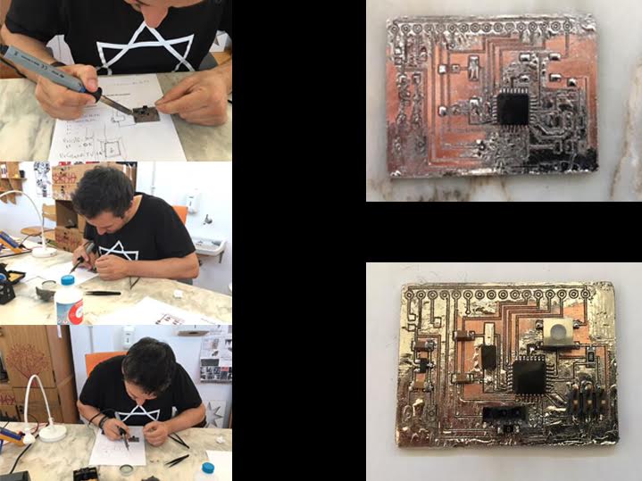
The final result wasn´t what I was expecting, during this phase I had some problems with my second final board, I ended up having some broken routes and with the solder I could not repair them and when i checked the routes and the components with the voltimeter, the board didn´t work ):
I want to make a new one, repeating the whole process...
Note - After all I had some luck because I had decided to make 2 boards, and the first one worked well so I was able to finish my Fab Feeder - C.A.T.'S
Files:
- Files :Final Board 1 - Milling - PNG - rml - schematic
- Files :Final Board 2 - Milling - PNG - rml - schematic
Step 4:
Cutting with laser cut, and starting to assemble (Week 7)
I used the laser cut machine to cut some pieces, I had already done the same work in the assignment "Computer - Controlled Machining" (Week7)
Files:
- Files : lasercut - Illustrator
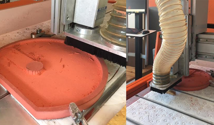
Step 5:
Using the CNC ROUTER to cut the orange Valchromat (Week 7)
Cutting and thinning the valchromat using the CNC Router, first we must choose what to do, Cut or thinning? I always choose thinning and then cut the the interior of the piece, only after I cut the exterior of the piece and the main reason is: to avoid undesaired movements of the piece which may lead to a damage of the work/machine.
Watch the VIDEO:
Files:
- Files : CNC Router - Art Cam - Illustrator
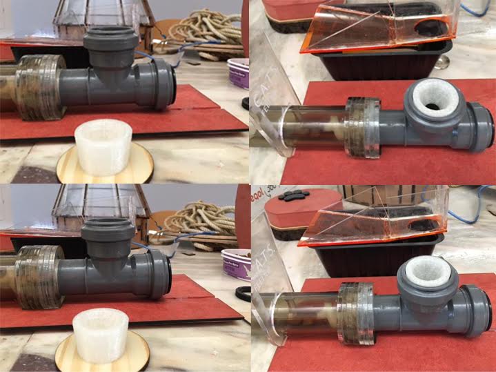
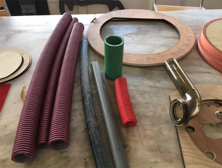
Step 6:
Build a Pipe
I found a recycle pipe, it came from a construction in Fundão, and I'll adapt it to the project, and I create an acrylic collet to connect the pipes.
Files:
- Files : Collet - Illustrator
Step 7:
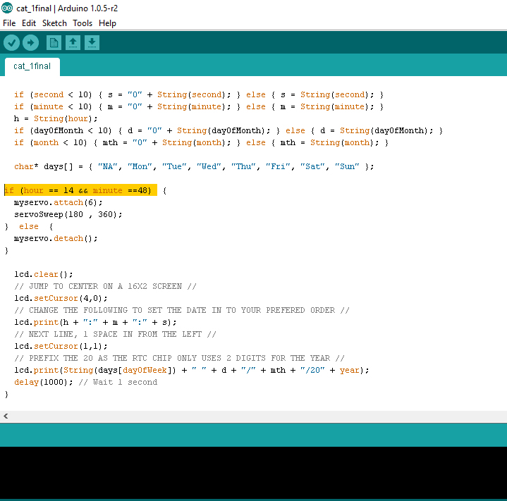
Programming
For programming was used the Arduino, telling to the 16x2 LCD Screen, the RTC and the Servo what to do.
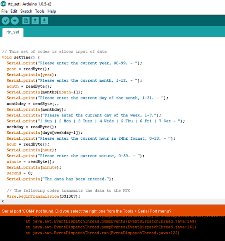
Note that there are two seperated files, rtc_set and cat_1final, the first one is to setup the RTC with the correct date and time, the second one is the code that will gather this feedback and then it is going to be used to activate the motor at a set time.
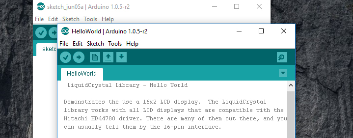
Firstly as a test, I tried the hello World, steps followed:
Open the arduino and then go to "examples" after that "liquidcrystal" and finally helloworld and the LCD screeen shows "Hello World"
After this we download the library to find the needed RTC (Real Time Clock), and we change the settings and values according with what we need
We must follow the steps and change the values in the code, in order to fill in the data that responds to the given questions:
"Code sample:"
void setup() {
Wire.begin();
Serial.begin(9600);
delay(2000); // This delay allows the MCU to read the current date and time.
Serial.print("The current date and time is: ");
printTime();
Serial.println("Please change to newline ending the settings on the lower right of the Serial Monitor");
Serial.println("Would you like to set the date and time now? Y/N
" Y" (yes)
"17" ( the year)
"6" ( the month)
"5" (the day)
"1- Monday" ( the day of the week)
"14" (the hour)
"41" (the minute)
After that verify and upload
After programming the LCD screen with the correct values (date and time) I programmed the servo according to the the time at which I want to feed the cats, in this example it was at 14 hours and 48 minutes.
*Important detail: once we have set the time in order to start the cat feeder, it is going to be working continuously for 60 seconds in this specific case because it is the amount of time defined by me after it stops.
Programming the final board 1 with the Atmel 328P:
To programming the board with the Atmel 328P I used this tutorial step by step:
- https://www.youtube.com/watch?v=CzY0dB2wfTw&feature=youtu.be
To programmig the Atmel 328P with the arduino, first of all I have to burn the Bootloader...
Steps:
- Open Arduino (I have the Arduino 1.8.3)
- Go to "File" next "Examples" and choose "Arduino ISP"
- After that go to "Tools" "Board" ando choose "Arduino Uno"
- Go to " Tools" " Programmer" and choose " USBtinyISP"
- Click "Upload"
- After that go to "Tools" choose " BreadBoardArduino"
- Go to "Tools" "Processor" and choose "Atmega328"
- Go to "Tools" "Programmer" and choose "ISP"
- Go to "Tools" and choose "Burn Bootloader"
- Click "Upload"
And it's done...
After that we just have to repeating the whole programming process from the "7 step".
Watch the VIDEO
Files:
Step 8:
Assembly of the recycled parts with the new parts
Step 9:
Build the container for food in press-fit acrylic
I built the container for food made of press-fit acrylic, and cut in the laser cutter machine, I had already done the same work in the assignment "Computer Controlled Cutting" (Week3):
Files:
Files : Touches - Container Press-Fit - Illustrator
Step 10:
Vinyl Cutter and Finishing touches
I used the vinyl cutter machine to cut the logo, I had already done the same work in the assignment "Computer Controlled Cutting" (Week3)
![]()
Files:
- Files : Vinyl - Touches - Illustrator
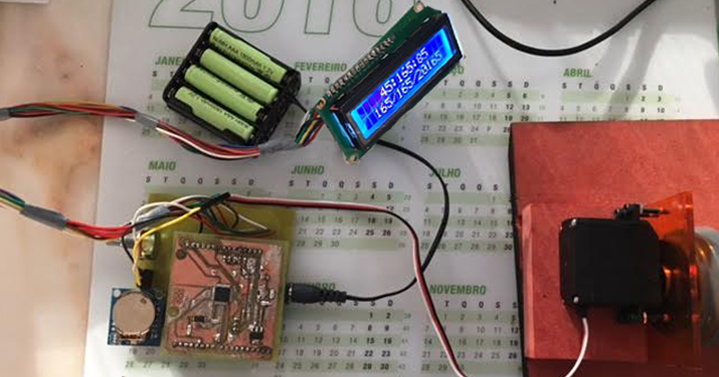
FINALLY
The C.A.T'S Feeder
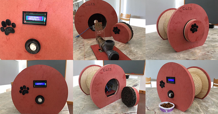
Fab Feeder C.A.T'.S on maintenance (:
Watch the VIDEO with the C.A.T'S. Feeder running:
Watch the VIDEO with the Cats using the C.A.T'S. Feeder :
The cats loved their new cat feeder, and their new toy ( the rope was a success).