
WEEK 3 (08 February 2017)
[Computer - Controlled Cutting]
In this class session me and my colleagues have designed and tested several types of Press Fit using wood, after this first job we made a personal work and I designed the tickets for an event that I usually organize known as: Sons à Sexta
( For this homework I used the Vinyl Cutter Machine and a Laser Cutter machine)
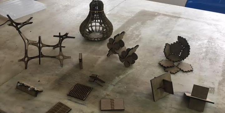
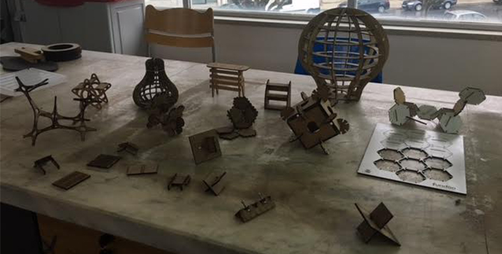
Press Fit Test:
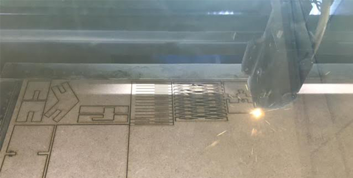
Using laser cut machine to test several types of Press fits and also to test several types of machine parameters to notice when it appears more or less burnt:
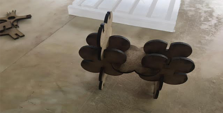
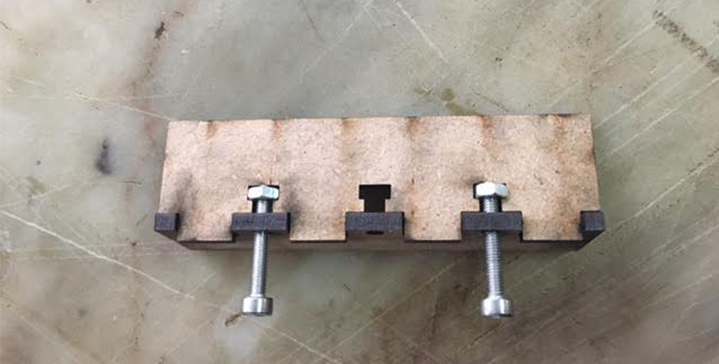
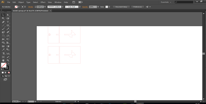
In the end, each of us focused on one specific press-fit, I did mine, and I tested it, to draw the press-fit test I used the 2D (Illustrator):
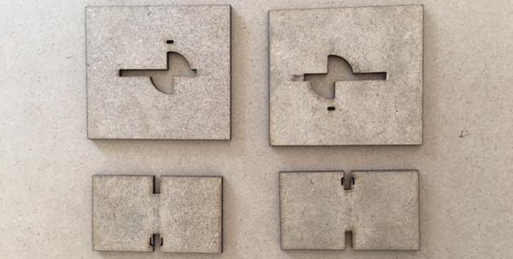
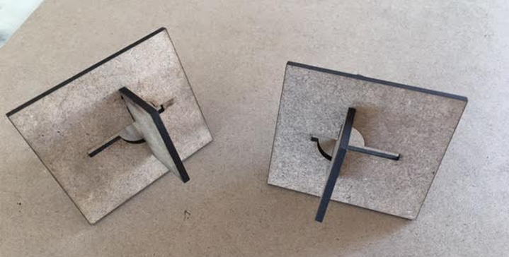
Final result:
Press Fit Test Personal Work :
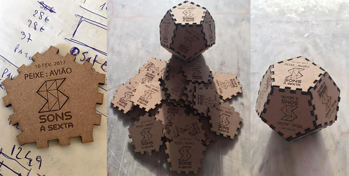
For my personal work I have designed the tickets for a concert, and with the set of 12 tickets we were able to build a press fit dodecahedron.
For modeling and Cading, I used the Illustrator 2D and I also used Parametric CAD SOLIDWORKS tools to obtain the vectorial drawings needed for cutting the wood. I Work with these tools on a daily basis, therefore I have a lot of experience in this type of work.
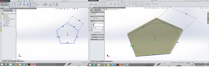
Using "SolidWorks" for the parametric drawing of each pentagon
I used Parametric CAD tools to obtain the vectorial drawings needed for cutting wood.
The parts were drawn with SolidWorks to simulate the assembly with all tikets and joints (very good tool to test this tasks). It is possible to test volume interference between parts, for instance.
Steps:
- First I chose the plane to draw "Top Plane";
- Then I used the tool "Polygon" to choose the number of sides and draw the pentagon;
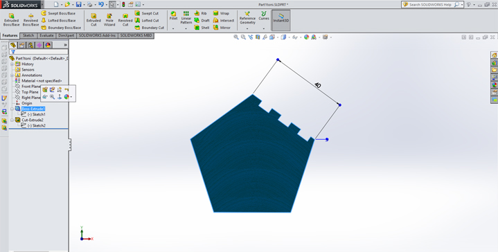
- After that I set the dimension of one side, I go to "Smart Dimension", (each side has 40mm);
- Then I used the tool "Equal" and dimensioned one side and that relation was used on all other sides;
- The next step was " Extruded Boss/Base" and I gave 3mm thick which is the thickness of the wood;
- I Made a new Sketch on the upper face of the "extruded";
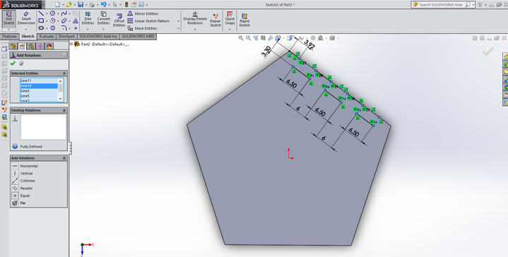
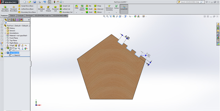
- After, I drew the fittings and set the right dimensions;
- "Add Relation" and I have difined all the lines: Perpendicular, Parallel and Coicident, into my draw;
- Finally I selected the Sketch and did an "Extruded Cut";
Explanation (step by step) with images:
An example of a sketch with constraints and dimensions and the parameters used to design the ticket:


Watch the video with the demonstration of my parametric design:
This is the virtual prototype to test subsystem assemble, and modules integration:
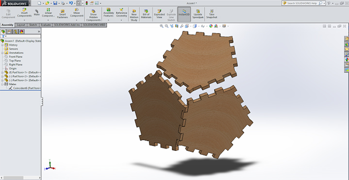
I used a lot of joints tikets (12 Pentagons ) to make the dodecahedron...
After that I generate the fabrication drawings, that are the orthogonal projection of the 3D model that means to the laser cutter (also very easy at this step). These files were saved in dwg format with precision dimensions.
To write in the ticket I use 2D (Illustrator)
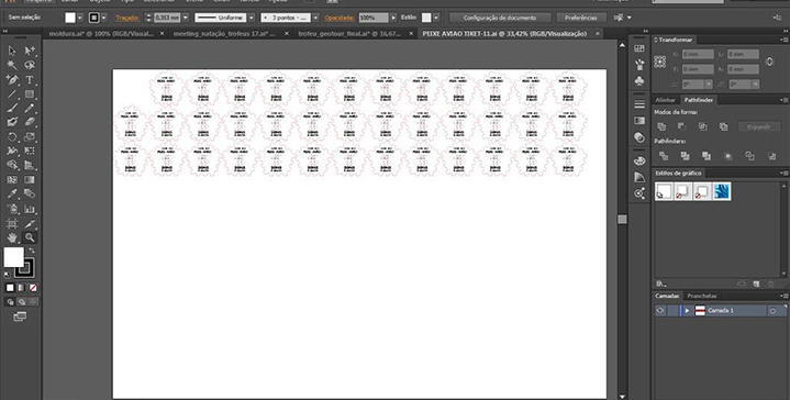
I also used the Illustrator to send the vectorial 2D models do the laser Cutter Machine.
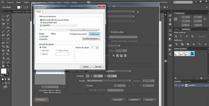
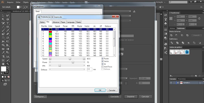
Using the Laser Cutter Machine (Spirit GLS)
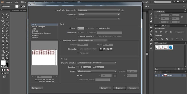
The parameters to making the object in wood were:
Black layer to ingrave thickness 0.001- Speed-60 Power-70
Red layer to cut espessura 0.001- Speed-2.5 Power-95
The final result was the assembly process, and the final product was a success for the audience of the concert: peixe:avião
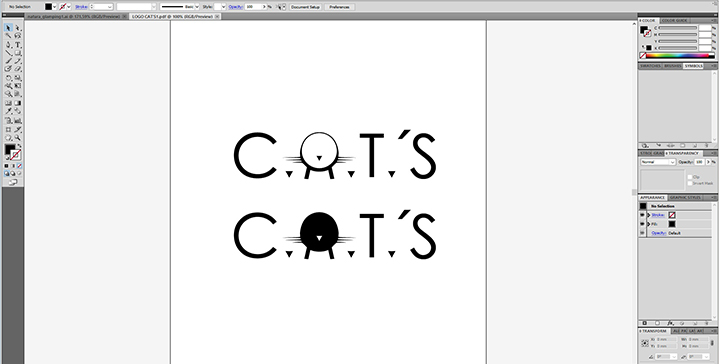
I used the Vinyl Cutter Machine to make the logo of My Final Project:
I have drew the Logo using the Illustrator tool,
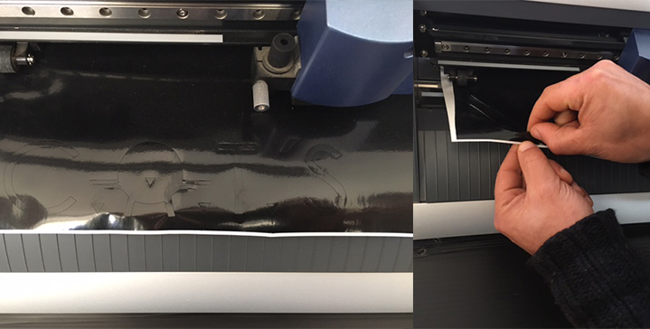
And I used black vinyl, and the Roland Vinyl Cutter to make this task.
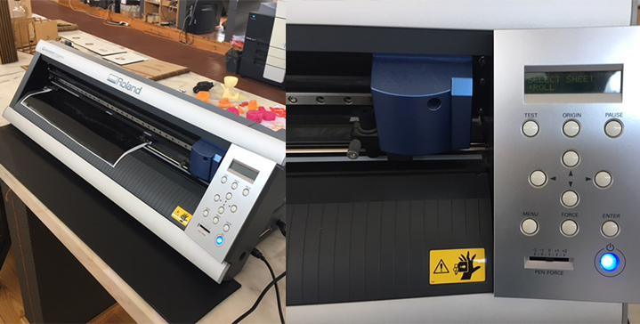
I used the Cutstudio to open the file from Illustrator in order to cut the black vinyl in the Roland cutter Machine.
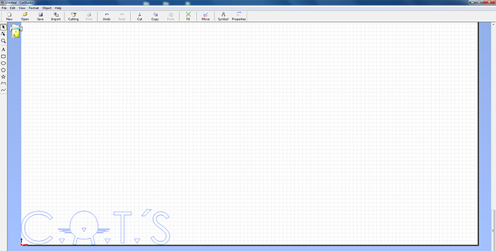
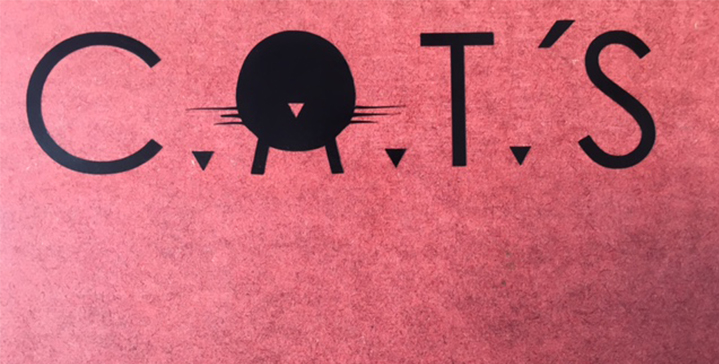
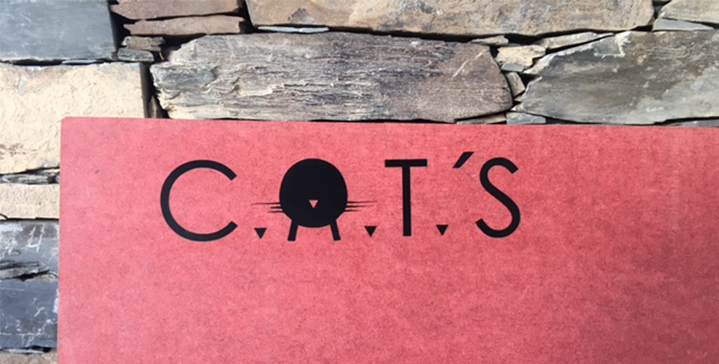
And this is the final result of my Logo, which will be used in my final project C.A.T'S Feeder
Files:
- Files : group.ai - cats aí - tiket aí - solidworks tiket