
WEEK 16 (17 May 2017)
[Interface and Application Programming]
The assignment for this week is to write an application that interfaces with an input &/or output device that I made and comparing as many tool options as possible.
For this week assignment we were introduced to the User interface and application writing world.
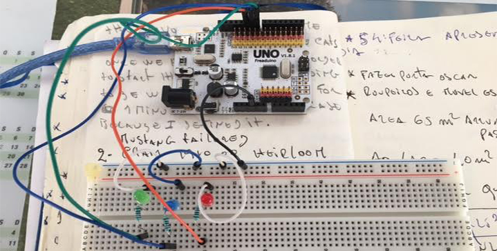
I will create an interface in "Processing" with 3 buttons that will allow us to control our 3 colored LEDs. I am also learning how to send Processing information to the board.
"Processing" is a programming language in visual context, created at MIT in 2001.
To get started, we need to download the latest version of Processing IDE that is currently version 3. To do so, just go to https://processing.org/ and download the appropriate version.
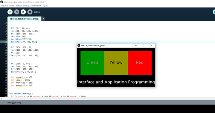
My goal here is to create an interface with 3 buttons in which we can click to light the LEDs we want. The first step in any Processing program is to create the window where we are going to draw (in my case, my graphical interface). I used the "size ()", method that takes as arguments the length and width of the window in pixels, in the same order.
I should also define the background color of my interface. In this case, black was chosen. To represent a color in "Processing", the RGB (Red Green Blue) system is used. Basically, all colors are any combination of these three base colors. For example, the brightest red is represented as (255, 0, 0). If we pay attention, this makes sense. We suppress any expression of Green and Blue and put the Red at its maximum value.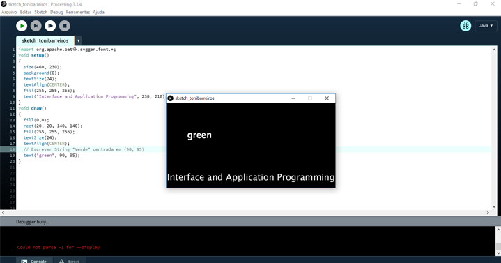

"Processing" Code:
import processing.serial.*;
Serial myPort;
int red = 150;
int green = 150;
int yellow1 = 150;
int yellow2 = 150;
void setup() {
myPort = new Serial(this, Serial.list()[0], 9600);
size(460, 230);
background(0);
textSize(24);
textAlign(CENTER);
fill(255, 255, 255);
text("Arduino LED Interface", 230, 210);
}
void draw() {
fill(0, green, 0);
rect(20, 20, 140, 140);
fill(255, 255, 255);
textSize(24);
textAlign(CENTER);
text("green", 90, 95);
fill(yellow1, yellow2, 0);
rect(160, 20, 140, 140);
fill(0);
text("yellow", 230, 95);
fill(red, 0, 0);
rect(300, 20, 140, 140);
fill(255, 255, 255);
text("red", 370, 95);
if (mousePressed && mouseX > 20 && mouseX < 160 && mouseY > 20 && mouseY < 160)
{
if (green == 255)
{
myPort.write("2");
}
{
myPort.write("1");
}
}
else if (mousePressed && mouseX > 160 && mouseX < 300 && mouseY > 20 && mouseY < 160)
{
// Desligar LED yellow
if (yellow1 == 255 && yellow2 == 255)
{
myPort.write("4");
}
{
myPort.write("3");
}
}
else if (mousePressed && mouseX > 300 && mouseX < 440 && mouseY > 20 && mouseY < 160)
{
if (red == 255)
{
myPort.write("6");
}
// Ligar LED red
else
{
myPort.write("5");
}
}
}
void mouseClicked() {
if (mouseX > 20 && mouseX < 160 && mouseY > 20 && mouseY < 160)
{
if (green == 150)
{
green = 255;
}
else
{
green = 150;
}
}
if (mouseX > 160 && mouseX < 300 && mouseY > 20 && mouseY < 160)
{
if (yellow1 == 150 && yellow2 == 150)
{
yellow1 = 255;
yellow2 = 255;
}
else
{
yellow1 = 150;
yellow2 = 150;
}
}
if (mouseX > 300 && mouseX < 440 && mouseY > 20 && mouseY < 160)
{
if (red == 150)
{
red = 255;
}
else
{
red = 150;
}
}
}
"Arduino" Code:
char valor;
int ledgreen = 8;
int ledyellow = 9;
int ledred = 10;
void setup() {
pinMode(ledgreen, OUTPUT);
pinMode(ledyellow, OUTPUT);
pinMode(ledred, OUTPUT);
Serial.begin(9600);
}
void loop() {
if (Serial.available())
{
valor = Serial.read();
}
if (valor == '1')
{
digitalWrite(ledgreen, HIGH);
}
else if (valor == '2')
{
digitalWrite(ledgreen, LOW);
}
else if (valor == '3')
{
digitalWrite(ledyellow, HIGH);
}
else if (valor == '4')
{
digitalWrite(ledyellow, LOW);
}
else if (valor == '5')
{
digitalWrite(ledred, HIGH);
}
else if (valor == '6')
{
digitalWrite(ledred, LOW);
}
}
Test the Interface:
Once I have both the Processing code and the Arduino code ready, I am ready to test it. To get my interface working, I started by connecting the "Arduino" to the computer and uploading the sketch. Once this is done I just have to click "Play" in "Processing" sketch, and my interface will appear. If all goes well, when you click on one of the buttons, the corresponding color LED will light up!
Watch the video:
I also followed this Processing tutorial
Write the Application that Interfaces with an Input Device:
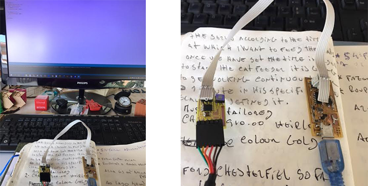
This week assignment also involves creating an application that interacts with one of the previously created boards. I will connect my button board that I've made on week 13, which has an input device ,a button, to communicate with a serial port (FTDI header).
To make the interface for my button board I had to program the board itself. Since my board has an FTDI header on it, I used the serial communication for sending and receiving data from the board.
To program the board with my modified C code, I installed AVRDude.The programmer used the .make file to install the .c file into my ATtiny44 microcontroller and the program successfully worked, to turn the button on and off with a press of the button.
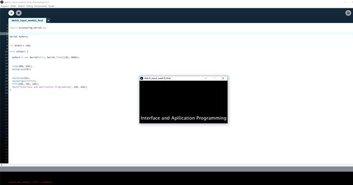
For this Interface I tried the simple read example for "Processing" application. Basically, a simple square responded to the clicks of my button, changed color from the display.
The code:
import processing.serial.*;
Serial myPort;
int black = 150;
void setup() {
myPort = new Serial(this, Serial.list()[0], 9600);
size(460, 230);
background(0);
textSize(24);
textAlign(CENTER);
fill(255, 255, 255);
text("Interface and Apllication Programming", 230, 210);
}
Watch the video:
Files:
- Files : Processing sketch - Arduino