Week 11:
Machine Design
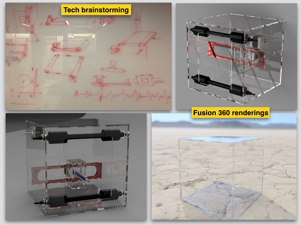
We started our group project from Mechanical Design mockup at Week 9 as a team with job definitions for each one of us and we finished it by working together on most of the missions. Each one of us can do 3D modeling and our fabrication skills are pretty same.
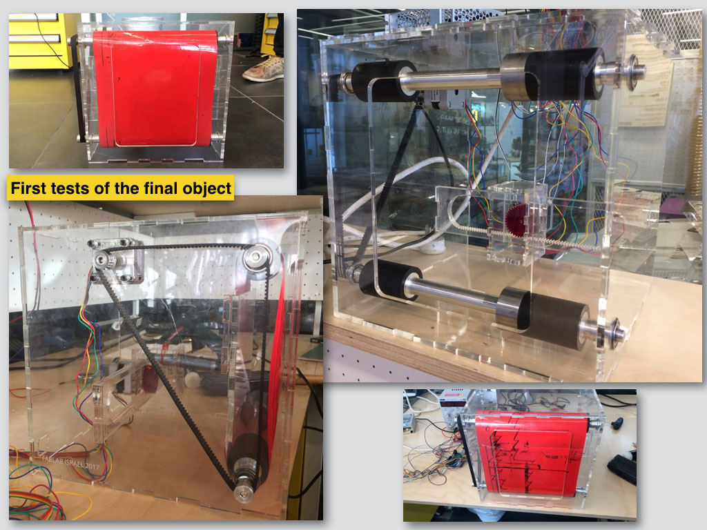
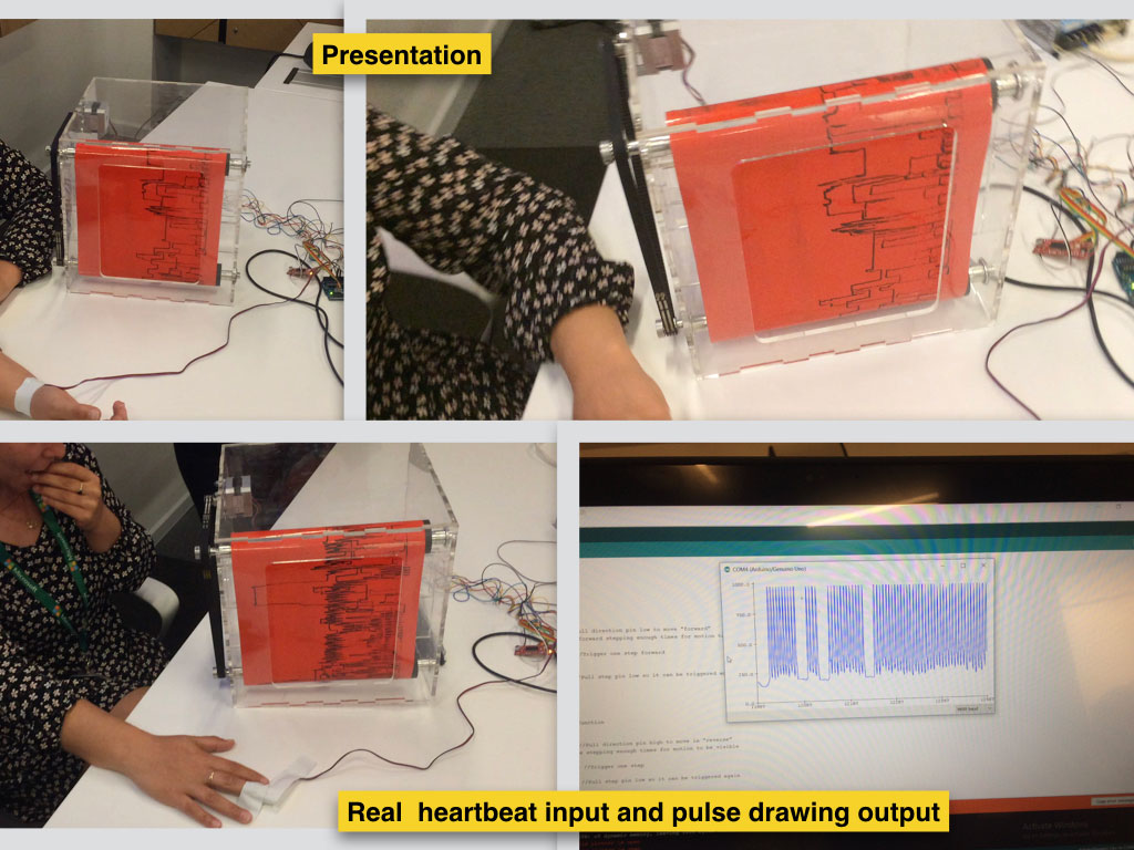
The machine we managed to build translates the analog infromation acquired from a heartbeat sensor into a left to right movement of a step motor. Another motor scrolles a whiteboard paper in endless loop and an erasable marker draws the pulse wave on the whiteboard paper loop like a monitor screen.
Our pulse plotter is a simple device that consists of the following:
An analog heartbeat sensor used as input data/analog signal.
An Arduino Uno board used as microcontroler.
Two step motors 12V used as out put to drive the axises.
Two step motors controller used as shields to make 5V powered Arduino control 12V motors.
An AC/DC converter 220V/12V used as motors power supply.
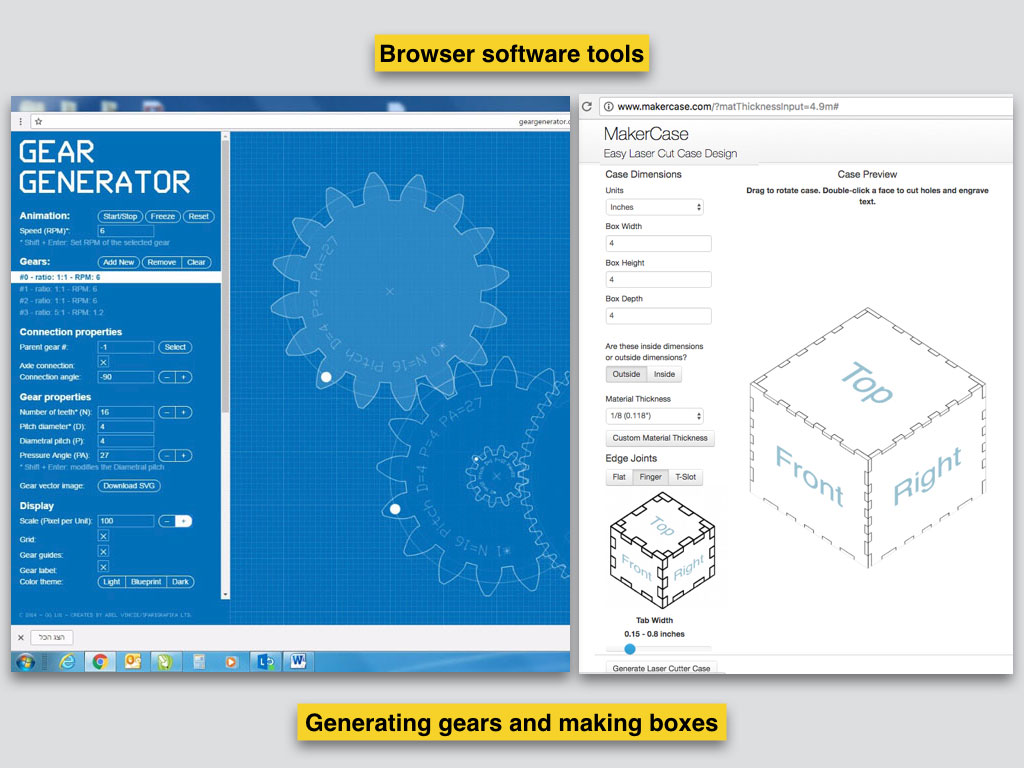
A belt and pulley mechanism used to roll the paper.
Rack and pinoin mechanism used for the marker motion.
Transparent Plexiglass monitor structure used to hold all the rigid + metal parts and to expose the inside mechanism.
After first mockup we started our second model that has 1:1 references to our final machine with only one difference - the material. By using plywood we saved the acril from mistakes and made them cheaper.
As the one who takes the measurements and fits them for the laser cut fabrication in his hands I made some mistakes but luckily we used plywood at this stage.
Working with Fusion 360 was very reliable because were able to share instantly the changes in the model. Most of my time was spent on modeling and the fitting preparations.
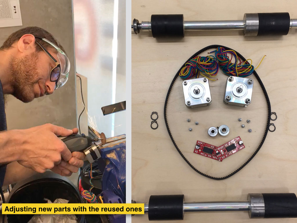
I had to assemble and to deconstruct back the machine few times to correct mistakes but most of the parts were tested “naked”, outside of the machine to make us possible to debug them without braking other parts on the way.
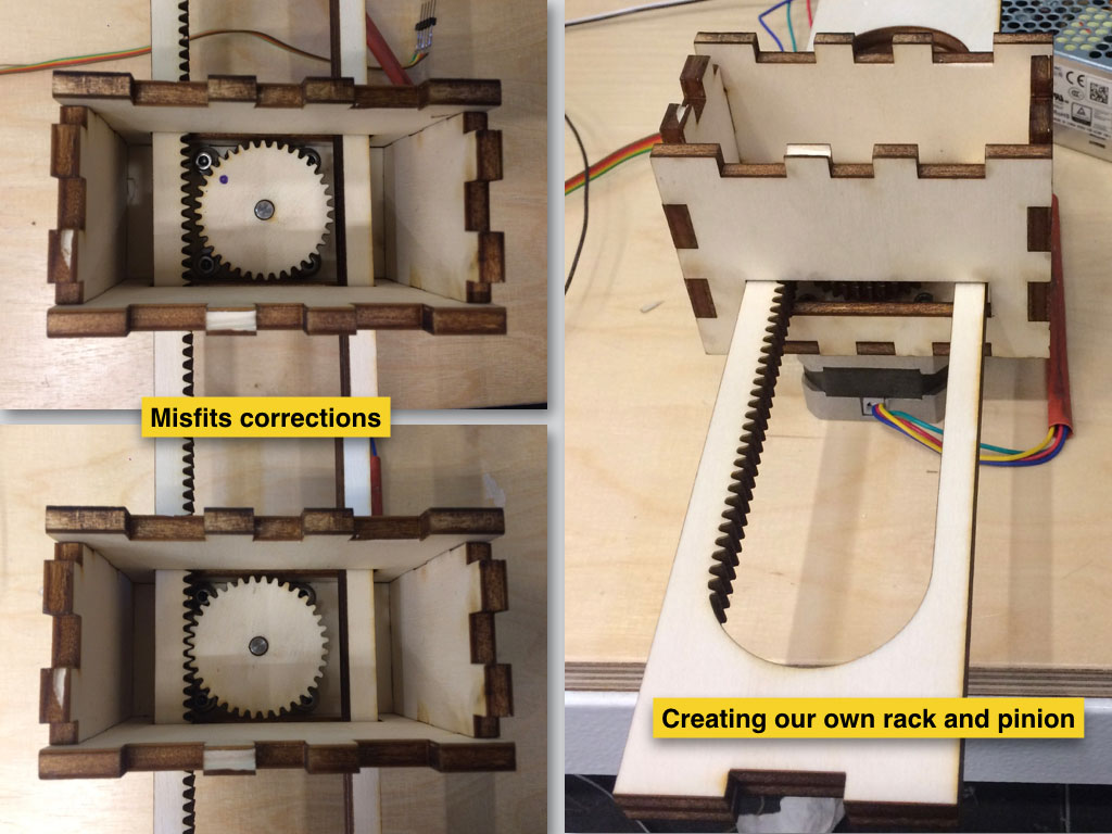
We created our own design of rack and pinion which worked fine. Of course the first version the sliding box with the motor went not smooth and we needed to get rid of the tension which caused by pen motor weight on the rack. We solved that with balance by spreading the weight of pinion and motor slide carriage from both of the sides of the rack.
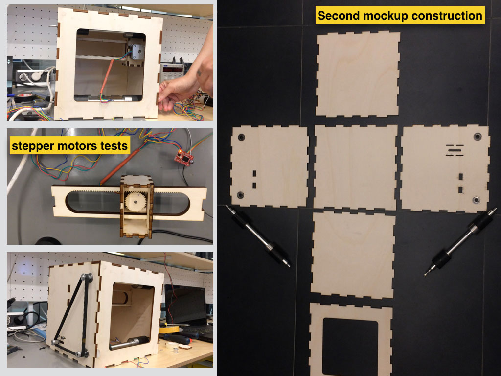
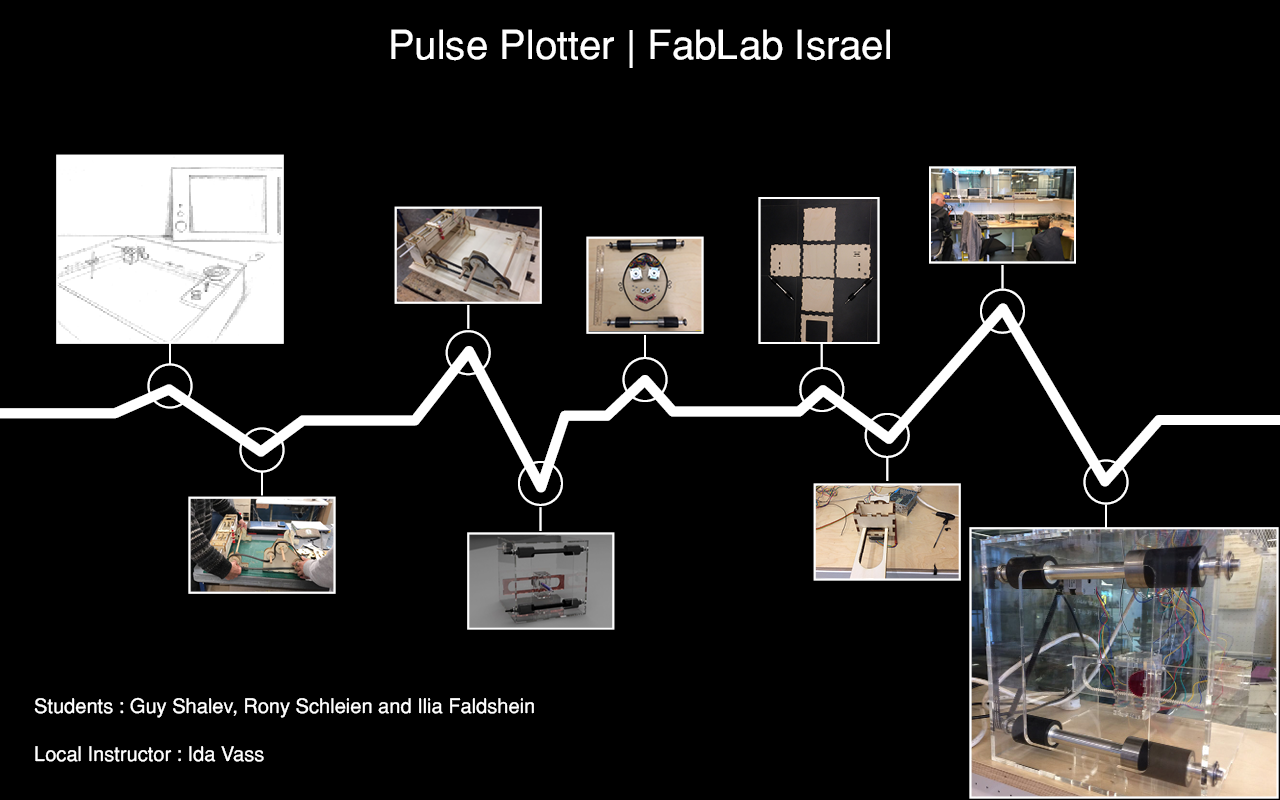
Finishing the second plywood mockup that works led us to the third and the final prototype.
Our lab project page