Yecatl: filtred RAINWATER DISPENSER
- Concept
- Process
BASIC IDEA
The idea of filtering and analyze rainwater becomes of the issue that in El Salvador and almost all Latin America, drinking water is not available to the majority, there are several geographical areas where its inhabitants have to walk for many kilometres to get it. What they do in rainy season, is to collect rainwater to use in their homes to irrigate their fields or wash clothes, but can not drink it because it contains many dangerous contaminants.
In El Salvador the rainy season lasts six months (May - October), then I came up with the idea of filtering the rainwater so that the inhabitants of those remote areas, with few resources, can use that purified water to drink or some other purposes in their homes.
I named it YEKATL because it means "purified water" in Mayan language.
My Final project consist in collect rain water to filter in a pipe with cotton, sand, rocks and activated carbon to be purified and make it potable. The purified water is held in a container that measures the water level with an horizontal level sensor and its pH level with a Ph electrode.
When the main container reaches the desire water level, the horizontal level sensor closes and then the pH electrode will measure and display the pH level in the LCD screen. If the water is in the range of 6,5 - 7,5 pH it runs to the blue container which is for drinkable water, if the pH level is not in that range, the water is still potable but not drinkable, so it runs to the green container for water to domestic use like wash the dishes, take a shower or water plants. The potable water pH level is between 6,0 and 8,5.
The whole project starts in collecting the rainwater and finishes in extract the purified water of the blue or green containers by user, but for Fab Academy project pourposes, I wont concentrate on how to collect or filter the water, I'll start on the step when the electro valve 1 opens to let the filtred water runs to the main container and the sensor 1 turns on indicating the water level, and I'll finish on the step when the electro vales 1 or 2 opens to let the pH measured water runs to the blue or green containers and the water level sensor 2 or 3 turns on.
I designed this project to be useful in rural areas of my country where potable water is scarce, but I'm going to develop it in Escuela Americana El Salvador too, because I'm attending Fab Academy 2017 to start the Escuela Americana Fab Lab to offer digital fabarication possibilities to students, faculty and community. We are planning to open the fab lab at the end of this year.
STAGES
Stage 1
The rain water runs through a pipe which conducts to the filter where the water electro valve 1 allows or forbids the water intake to the main container depending on the water level sensor 1.
When the water level is going up and reaches the water level sensor 1, it closes and the electro valve 1 closes too forbidding the water entry.
The water electro valves 2 and 3 are closed and water level sensors 2 and 3 are off at this time.
Stage 2
Once the electro valve 1 is closed, the pH electrode makes a measure and shows it in the LCD screen. The pH measurements are performed on a scale of 0 to 14, with 7.0 considered neutral (drinkable water). Measurements with a pH below 7.0 are considered acid and above 7.0 are considered alkaline. As the water is already filtered and potable, the pH level should be in the range of 6,0 and 8,5.
Stage 3
If the pH level is in the range of 6,5 to 7,5 the water electro valve 2 opens allowing the water run from the main container to the blue container. This container has the water level sensor 2, when the water reaches the level it turns on and in that moment the electro valve 2 closes again. The drinkable water is emptied out by opening a water tap and once is empty, the user should push the reset button to start the process opening the water electro valve 1 again.
If the PH level is different than range of 6,5 to 7,5, the water electro valve 3 opens allowing the water run from the main container to the green one, this container has the water level sensor 3 making the same process than the blue container. Once the user pushes the reset button, the water electro valve 1 opens starting the process from the beginning.
FABRICATION PROCESS
In the fabrication process I will use the following to create all the parts and componentos of the project:
Machines:
MBot Grid II+
Graphtec Robo Pro
Trotec Speedy 300
Software:
Rhino for Mac 5.0
Adobe Illustrator CC
Autodesk Eagle
Arduino IDE
Components:
1 pH electrode
3 water electro valve
3 water level sensor
1 LCD screen
1 reset button switch
1 relay module
Materials:
PLA red, yellow, green and blue
Plastic containers
Water hoses
Water taps

PROJECT TIMELINE
For the project develops I will follow this timeline:

ELECTRONICS
For the electronics I design the board and schematic in Eagle, then with the same process as asignment 6, I had my PCB board finished. After that I proceed to solder the SMD components first and then the through hole ones.
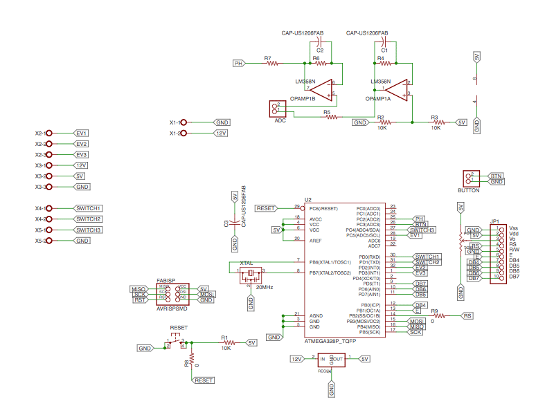
I had to discard a previous pcb that I couldn’t use because I didn’t know that when I design in two different layers, the SMD components face should be mirrored and I didn’t do that, I realized my mistake until I was trying to solder the OpAmp and the pins doesn’t match, so I had to desolder everything and make a new pcb in the right way again.

This is the correct Yekatl PCB.

I could solder everything without problems now. One of the 0 Ohm resistor is just a jumper because I couldn’t connect any other way the paths between the ATMega 328 and the LCD pins, the other 0 Ohm resistors and the capacitor I didn’t use are because the electronics instructor explained me that due I didn’t have the pH sensor yet, may be I’ll need to add some different value resistors to make it work.

PROGRAM
With the help of the Hackerspace instructor, I program all Yekatl functions as I explained before using Arduino IDE.
First include Liquid Crystal library to be able to set the LCD pins.

Then I declared all the pins numbers used corresponding to the ATMega 328 for the micro controller to know what is what. I also declared all the valves (electro valves) and switches (water level sensors) state and if they are INPUT or OUTPUT.

Next step was declared the PH_METER variable that I used to calibrate the pH sensor, to do that, the PH_METER value should be 1, if is 0 it means that all the other program functionalities are running instead.
In the moment I connected Yekatl to power the screen shows “YEKATL” in the first line and “Push to start” in the second one, to do that I declared in the lcd.setCursor (0, 1) which means that the firs wording should be in the first line (0) and the rest in the second one (1).
Here I also declare that while pin_btn is HIGH, which means I already push the button, the LCD shows the message “Filling main tank”, so the pin_EV1 (electro valve 1) should turn LOW letting the water flows into the main container and when the pin_switch1 (water level sensor 1) turns HIGH the EV1 turns HIGH, so it closes.

Now the LCD prints the PH level using the formula I explained in pH Calibration. Next I declared that if phX10 is in the range of 65 and 75, the pin_EV2 turns LOW and let the water flows into the “DRINK” water container and should stop when the pin_switch2 turns HIGH, the message “Drink safe water” appears in the screen.
If the pH value is other different to that range, the pin_EV3 turns LOW letting the water flows into the “HOUSE” use water and it should stop when pin_switch3 turns HIGH, the message “House use water” appears in the screen, and with a delay of 5 seconds the program restarts and is ready to start again..

FUNCTiONING
I had to face several problems during the process, I’m still doing it!, the principal issue was that due to problems in customs, the valves and pH sensor came the Tuesday afternoon before my final project presentation, so I couldn’t make any real test with them, and the water level sensors came two days after the presentation. The only thing I could do before that was test the program connected to an arduino, using a potentiometer emulating the pH sensor.

Obviously the first time I connected it, DIDN'T WORK!! because I had not been able to do tests in advance, besides being a real disaster of cables and components, and taking in consideration that the water level sensors hasn't came yet at this moment. Other important issue is that the hose connectors seals were not enough and I had to seal them with silicone to prevent water leak.

LASER CUTTING
Facing the mess of not having a stand to set Yekatl, I decided to design one, to do that I used a Trotec Speedy 300 laser CO2 machine tu cut the stand, legs and front screen panel.

3D PRINTING
I design in Rhinoceros 5 for mac the hose connectors and the bottle holders, to print them I used a MBot Grid II+

Trying to solve the very serious leak in hose connectors, I detected that the green PLA may be didn't melt well so I had to change the connectors I printed to a metallic ones, because I tried twice with different infill settings and every time they split in two parts and the water leaks in the hose connector pin, not in the bottle because I already seal them with silicone.

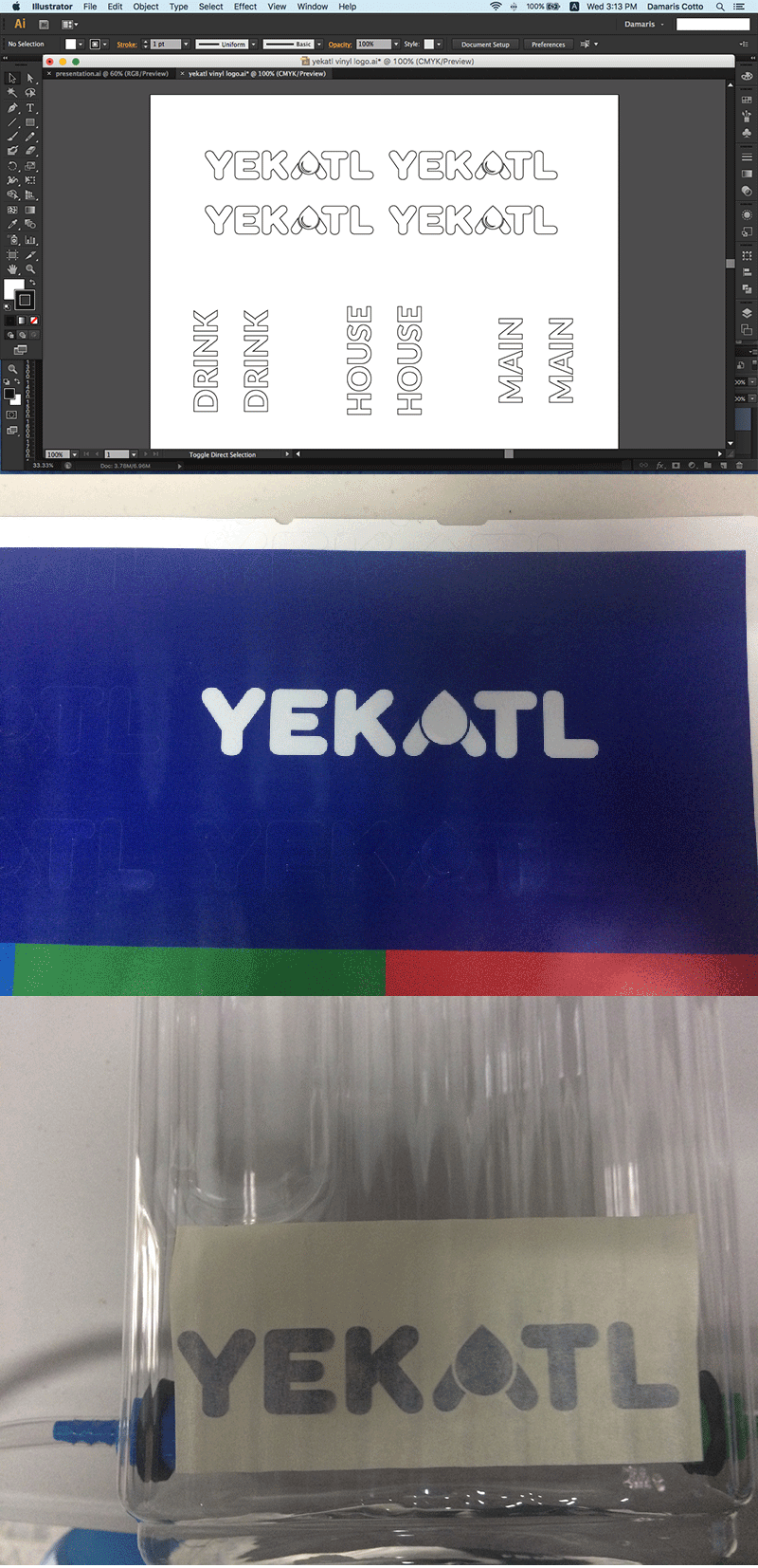
VINYL CUTTING
For this part of the project, I used the logo I designed in week 2 and cut it in adhesive vinyl as well as the bottle names.
TESTING
Once I finished the program, I tested its performance using an Arduino UNO and a breadboard. The pH sensor han't came yet at this moment, so I had to simulate it using a potentiometer.
Final Project - Fab Academy 2017 from Damaris Cotto on Vimeo.
pH SENSOR TEST AND CALIBRATION
To calibrate the pH sensor, I had to find the way to make comparisons so I used a testing kit for aquariums. The test kit is to mesure pH in the range of 4,5 - 9,0 and consist in mix 5 drops of pH reagent with 5 ml of liquid, I used lemon juice, filtered water and chloride for the test. The mixture of liquid and reagent turns into different colors that I had to compare with the chart included and set the most approximate pH level of each one.
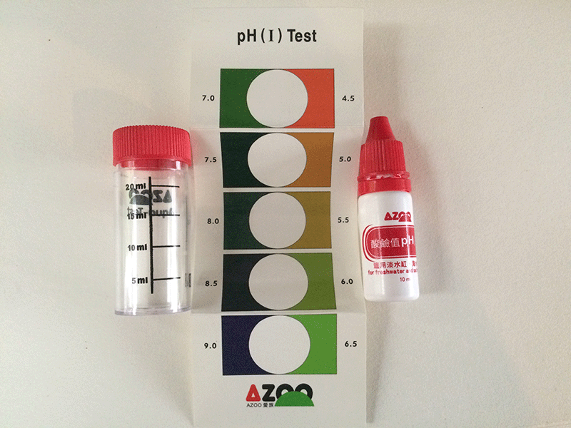
The results were:
- Lemon juice - 4,5
- Purified water - 7,5
- Chlorine - 8,5

Next step is proceed to make tests with the pH sensor and read it, as it shows ADC values, I had to translate to pH values declaring them in the program.
The ADC units were:
- Lemon juice - 534
- Purified water - 477
- Chlorine - 421

The program includes the variable PH_METER that I used to calibrate, the variable use to be in 0, but if I changed to 1, it shows only the pH measurement in the screen that I used to calibrate and set the convertion values of ADC to pH.

Now the program shows in the LCD screen the pH value instead of ADC units.
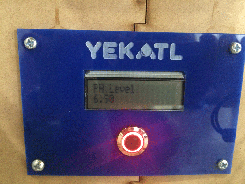
This is how my final project looks now.

The LCD screen shows what is doing during the process:

This short video shows how it works.
YEKATL from Damaris Cotto on Vimeo.
The Final Project was sponsored by: