Computer Controlled Cutting
For this week's assignment, it's required to do 3 main tasks:
- Group assignment: make lasercutter test part(s), varying cutting settings and slot dimensions This is the frame where the pieces will fit.
- Individual assignment (1): Cut Something on the vinyl cutter.
- Individual assignment (2): design, make, and document a parametric press-fit construction kit.
I. Design and Make a Press-fit construction :
Parametric design is a process based on algorithmic thinking that enables the expression of parameters and rules that, together, define, encode and clarify the relationship between design intent and design response.
For doing this task, I decided to try another CAD tool since last year I tried Inkscape for parametric design. I used Fusion 360, and it turned out to be a really nice CAD tool with easy interface and lots of tutorials to help you start.
First of all, I did some tutorial research and I found this 7 minutes video explaining how to design parametirally using Fusion 360. It was a good start.
Next: Getting to work!
To draw the design, I started copying the tutorial and drawing the slot in form of lines.

To create that parameter to change, I used "Changing Parameter" from "Modify" toolbar. You add your parameter, give it a name, its expression and its units.
 |
 |
| Changing Parameter option | Adding Parameter. |
After adding "slot" as the main parameter, I indicated which dimension to be assigned to be parametric. Then, I tested changing the parameter from 3mm to 5mm.
 |
 |
| Assigning Parameter | Testing changes. |
The next step was to design the part. For this I drew a circle and made a circular pattern of 8 pieces for the slot and then to show the real shape, I extruded the sketch 3mm as shown in pictures.
 |
 |
| Sketch. | Extruded piece. |
Designing the rest the same way, this is the whole kit together.

Then, prepare the sheet, set the laser settings and off you go!

I get those final shapes.
 |
 |

Puzzle Casing:
For the Final Project, I needed to have a puzzle case. I used Corel Draw to design the box, I added some kids and animals drawings, and cut it on the laser cutter.
 |
 |
| design | Implemented box |
II. Cutting Something on the Vinyl Cutter:
Vinyl cutter is one the most interesting and fun machine for me in the lab; It's extremely easy and you can do so much with it.
For Cutting something on the vinyl, you need to (1) Set your machine and (2) Prepare your file.
To prepare your file, there are in 2 different ways: One using Fab Modules and the other one is using Cut Studio (the windowns operating program that comes with the machine driver). I'm going to show how can we do it both ways.
Setting your machine:
1. Fix your sheet to the machine and make sure the rolls are placed correctly on the white marks (the start must be within the main white mark "placed to your extreme right"). These marks play the role of the sensors that measure your sheet and gives you the dimensions within which you'll implement your design.
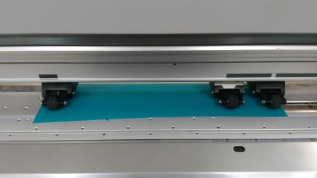
2. Open the machine and select your work piece (Roll, piece or edge).

The machine will measure your sheet. Save these dimensions, we'll use them later.

Preparing your file:
Using Fab Modules:
1. Open Inkscape and set your document properties: Document Properties are mainly the background and dimensions;

First of all, make sure your background is not transparent, change it to "White" or any solid color. White value is "255" in the RGB code.

Secondly, is the change the dimension of your piece. In this, you will insert the dimensions read by the machine and that you saved earlier. Just make sure you pick the right units (usually, mm).

Now, your piece is ready for your design.
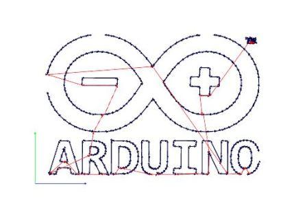
Start putting your design in there, whether is shapes or imported pictures. for me, I chose to make "Arduino" logo sticker.

1. Import your picture and set its place within the design area.

2. Extract your outlines using the "Trace Bitmap" feature. Select "Edge Detection" and then "Update"..

3. The last step is to transform your object to path thorugh "Oject to path" command, so that the machine can read your object as a path to trace.

Now your file is ready to be up on Fab Modules.
Select your input as "drawing (.svg)" and select your file.

As output, select "Roland Vinyl (.camm)" to generate your machine G-code file. Then, as a process, choose your material; here we use vinyl, so I chosed "Cut Vinyl"

On the right of your screen, you'll find the settings of the cut, the force, the velocity and the origin. These parameters change with every material as each one of them needs a certain force and velocity to be cut accurately. Then click "Calculate.

Now your file is ready. Just click "Send" for the machine to start.
Using Cut Studio:
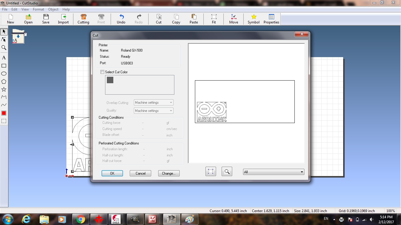
The second way to prepare your file is to use "Cut Studio".
To Prepare your file:
1. Open the cutting program "Cut Studio". Set your piece dimensions (measured by the machine) by going to "Cut Settings", Choose "Roland GX-500" and click property; insert the dimensions or you can just click "get from machine".


2. Import your image to the cutting area and adjust it to fit.

3. Get the outlines of your picture by selecting your pic and right-clicking on your mouse and select "Get outlines".

4. Just Click "Cut".
Getting your sticker:
1. After finishing cutting, take out your piece and weed it (Remove the parts you don't need).

2. Put the adhesive tap or regular transparent scotch tape (in case you ran out of adhesive tape) on your design to transfer it.

3. Stick your design on whatever surface you want.
4. Remove the tape slowly and carefully.

And Here we Go! :)

III. Make laser cutter test parts:
For this, we made 3 main things. We made the varying slots dimensions and tested the laser cutter cutting, engraving speeds on various materials and finally, engraving pictures with high quality. My role was to document the various speeds of materials and pictures engraving; and you can find the slots dimensions on Assem's assignment page.
About the Machine:
Our machine is MT3050D. It's a 60 Watts CO2 laser machine with bed dimensions of 60 x 50 cm. You can find full specification on Morn website.
The materials we tried are: Polywood of thickness 3mm, Acrylic of 3mm, Cardboard, Compressed white Foam and regular foam.
In those pictures, we were trying different cutting speeds to, also, review the burn traces at the back of the board. The test was made on Power 70, and speeds "10", "14" and "15".
| Front | Back |
|---|---|
 |
 |
 |
 |
 |
 |
And this was the trial on the regular foam and compressed one.
| Regular Foam | Compressed Foam |
|---|---|
 |
 |
After several trials of engraving and cutting on different speeds. We came out with the optimum following settings. Note that these depend on the laser tube lifetime. As time passes, the laser tube power becomes weaker and thus these settings change. So, you'll be needing to recheck those every 3 months of work.
| Material | Mode | Power | Speed |
|---|---|---|---|
| Polywood 3mm | Cut | 75 | 10 |
| Polywood 2mm | Cut | 70 and 50 (For Flexi-wood) | 10 |
| Acrylic 3mm | Cut | 75 | 8 |
| Acrylic 6mm | Cut | 85 | 8 |
| Foam | Cut | 20 | 25 |
| Compressed Foam | Cut | 20 | 50 |
| Cardboard | Cut | 85 | 5 |
As for Polywood engraving, you can check the map we did for Polywood in the pictures below.


For the rest of the material, here are the recommended:
| Material | Mode | Power | Speed |
|---|---|---|---|
| Acrylic 3mm and 6mm | Scan | 30 | 220 |
| Foam | Scan | 50 | 350 |
| Cardboard | Scan | 50 | 100 |
As for pictures, we used Bitmap handle feature in RDWorks program to edit the picture. But first of all, you need to have a picture with a good resolution and little noise (secondary details).
This feature will open a window in which you can control various settings of the picture. Now, vary the following settings until you get the best out of the picture:
1. Brightness.
2. Contrast.
3. Resolution must be in range of 1000 up to 1500.
4. Frequency must be in range of 50 up to 70.
5. Dither, by select one of these types:
- Net graphic.
- Dot graphic.
- Black and White.
- Gray scale.
- Sharpen.
As for speed recommendation, we go for not greater or less than "150" to be able to get the finest details of the picture; and for power, we recommend, a maximum of "10" or "15".

 |
 |
One last thing you'll need to know about your laser, is to watch out for the temperature of the water serving the cooling cycle. It must not exceed "25 degrees celcuis", as if it does, the machine will not cut properly and you'll have a very low engraving quality as well.