Third Assignment
Computer Controlled Cutting
This assignment is about:-
1-Design, make, and document a parametric press-fit construction kit which can be assembled in multiple ways
2- cut something on the vinylcutter
"
Press-Fit
Parametric construction kit
It's something consists of pieces that fit together like legos.
The main parts
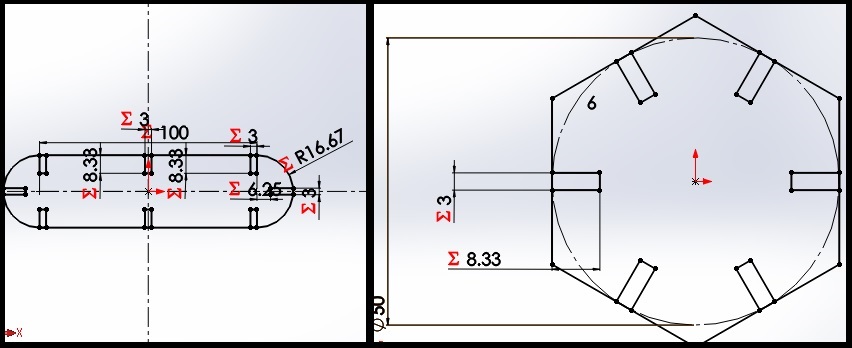
The design cosists of two main parts the Hexagon and the Strip
both of them has many slots to be fitted in many different ways.
You will notice -in these screenshots from SolidWorks- many different Sigma signs which means that these dimensions are related to parameters
Parametric design
Parametric design is a process based on algorithmic thinking that enables the expression of parameters and rules that,
together, define, encode and clarify the relationship between design intent and design response.
in SolidWorks this is how it looks to make a parametric design.
You will find a good tutorial to be familiar with using equations in SolidWorks in this Link

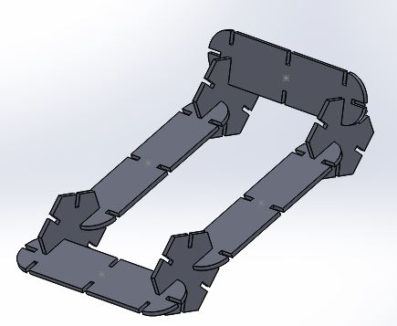
A sample of assembled parts
Here it's a sample after assembling some parts
In this gif you can see how changing the parameters changes the whole design
Selecting the right dimensions of press fit
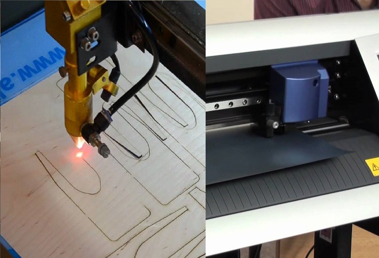
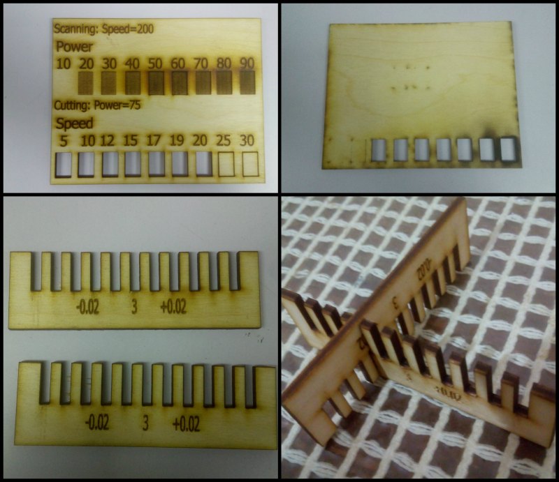
One of the important things while cutting on a laser cutter is to know which cut slot width is the right one
It could be done by making these two parts and making some tests.
after selecting the best cutting power and speed (the fastest one that could cut), We made these parts (which looks like a comb) to select the suitable width of the press fit which doesn't make a clearance fit.
you can check the Whole documentation for the group assignment and other's work you can go HERE
after knowing the desired power and speed you can cut your parts as described in the next steps.
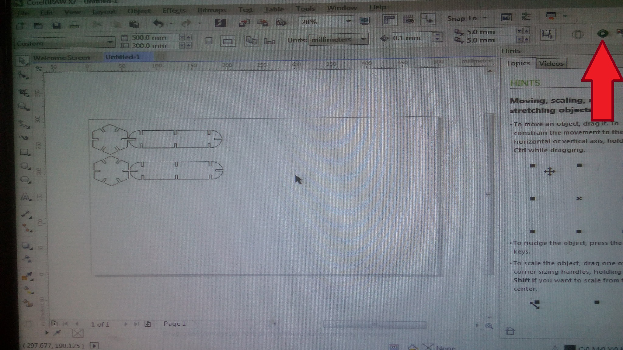
Using Corel Draw
the program associated with the Morn Laser cutter is RDWorks you can also use Corel Draw as This Tutorial
describes.
after importing your drawings you can send it to RDWorks to choose the options (or you can import them directly to RDworks).
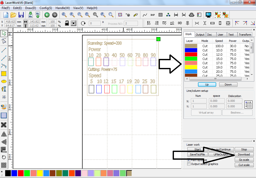
Choosing Power And speeds
You have to assign a colour for each line and you will choose options for each colour like Power and Speed, you can also select if it's making cutting or scanning process.
then press download and name your file that will be sent to be able to operate it on the machine.
Your file is ready!
As simple as that you will have your file ready to be machined on the laser cutter
(I put the speed and power on the construction kit parts as the same as the previous picture.)
I chose Speed 20 and power 75%
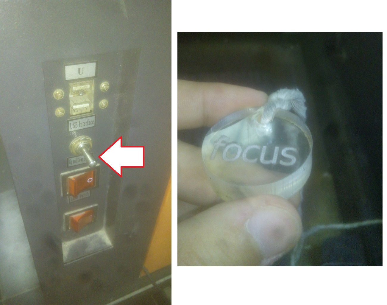
Adjusting the focus
By this lever you can move the table of the laser cutter up and down, you have to calibrate it that the distance between the laser output and the machined workpiece equals this thickness (the focal length)
using your file on the machine
you will find your file by pressing the "file" button, then you will find your file in the memory files
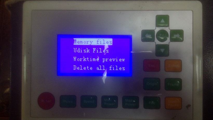
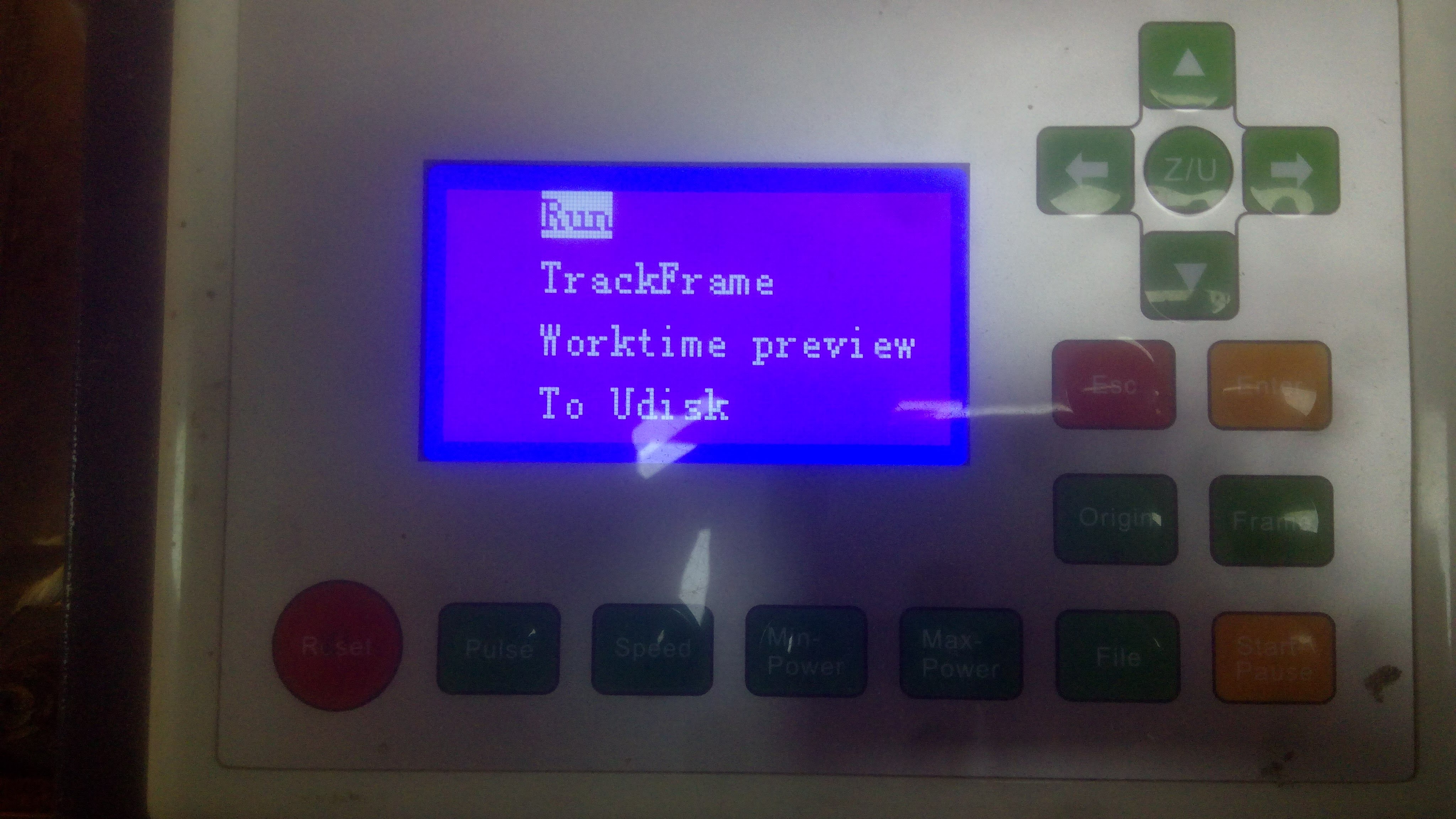
Some options
You can know your the needed time for your file to end cutting by choosing worktime preview or check the working area needed for your file by choosing Trackframe.
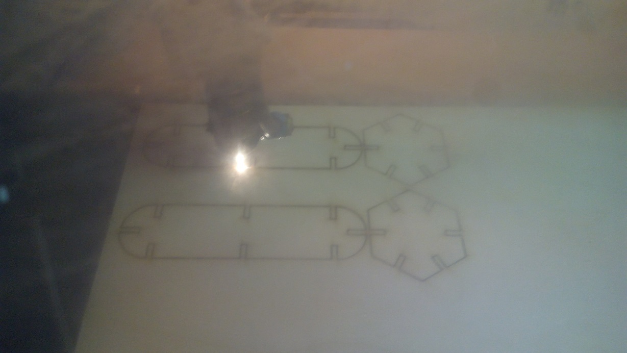
when you are sure about the working area and the focus you can press run to start operating.
while cutting
for your health you have to close the door not to inhale the fumes.
After cutting

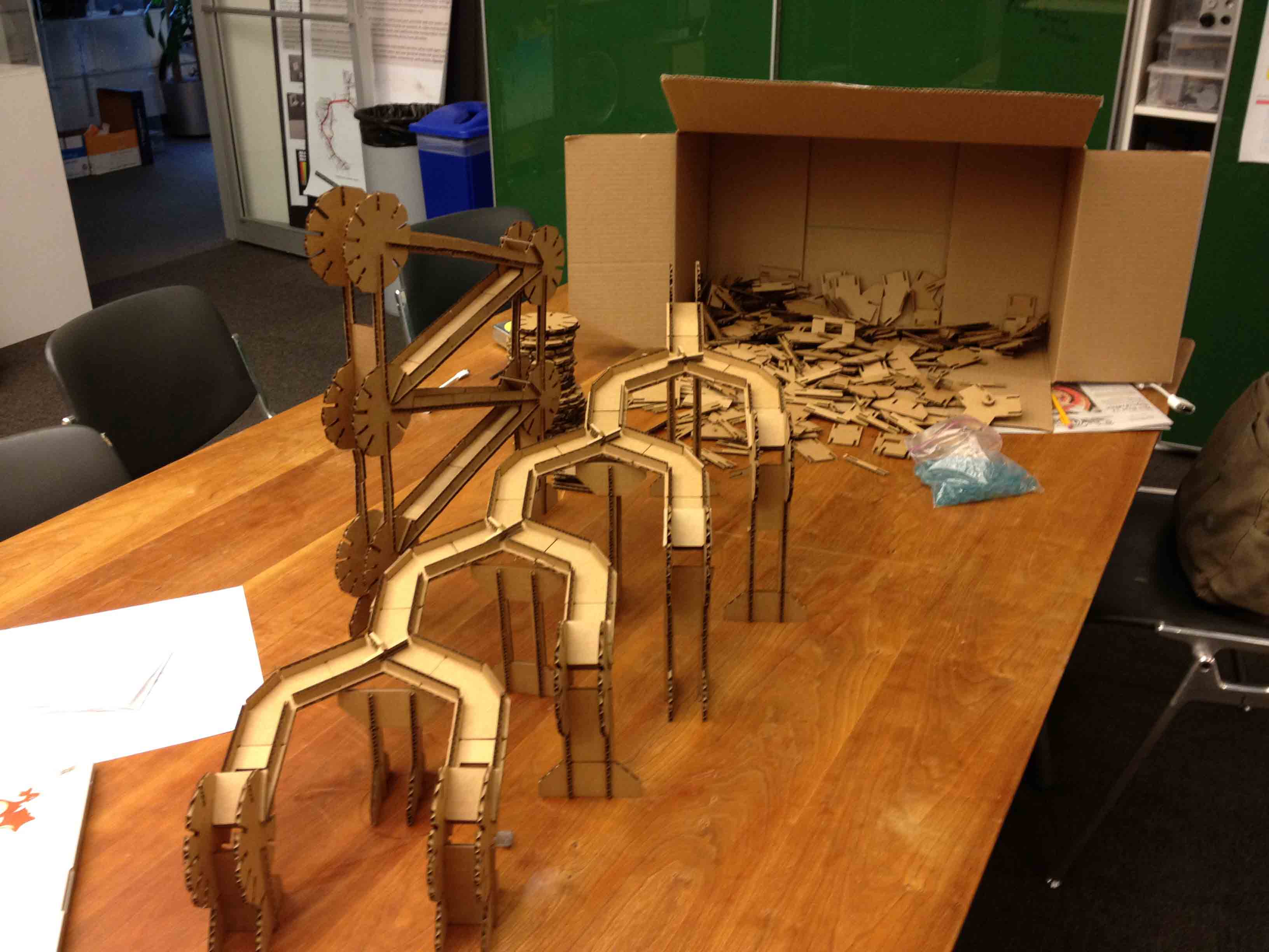
Assembled Parts
After selecting the right width of the press fit I cutted many parts to play with and assemble them in many different ways.
And here are some examples after assembling
It could be fitted in infinite ways but I really like that cup coaster :D

Vinyl Cutter
This task was about cutting something on the vinyl cutter machine.
I will explain the main steps.
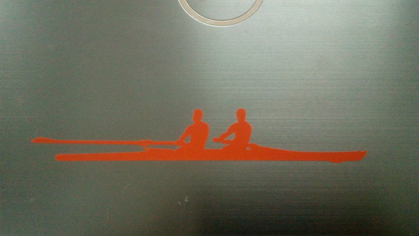
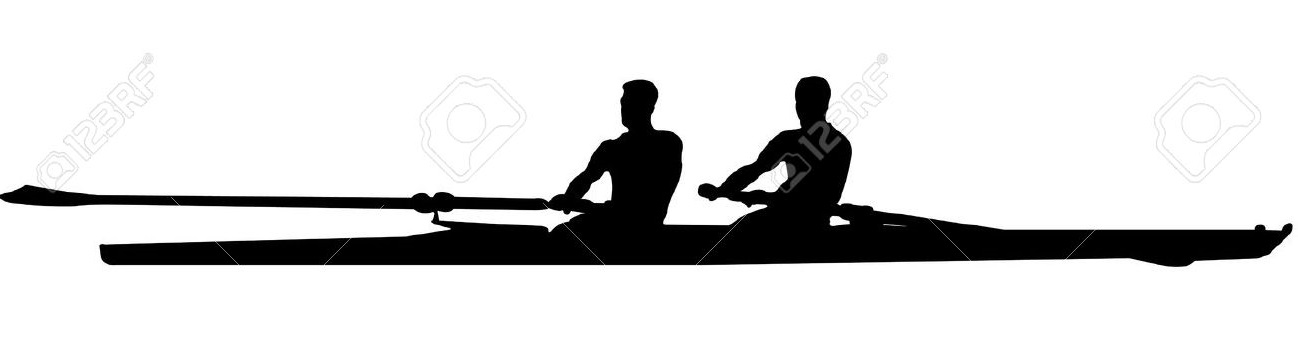
The first step is finding a good picture
As I was a previous rowing player I thought it would be a good idea to put something on my laptop makes me remember these great days.
here it's the chosen one :D
I got this picture from Shutterstock from this HERE
made by B. Sanja
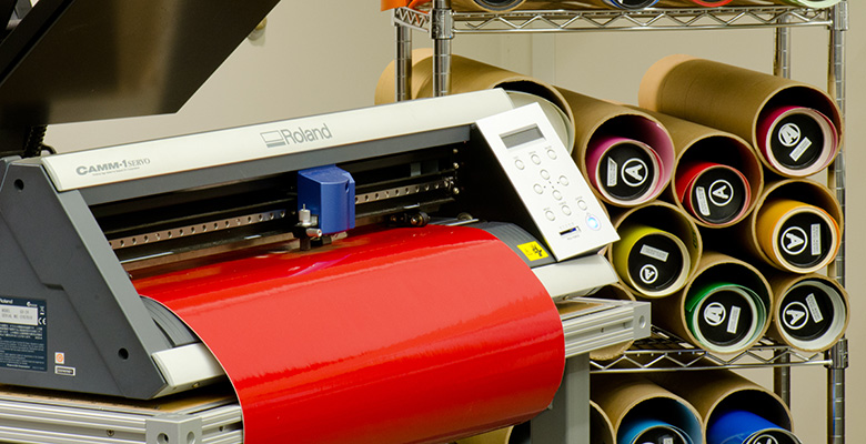
Using Cut studio
As in our lab we are using Roland GX-24 the suitable CAM software is Roland CutStudio.

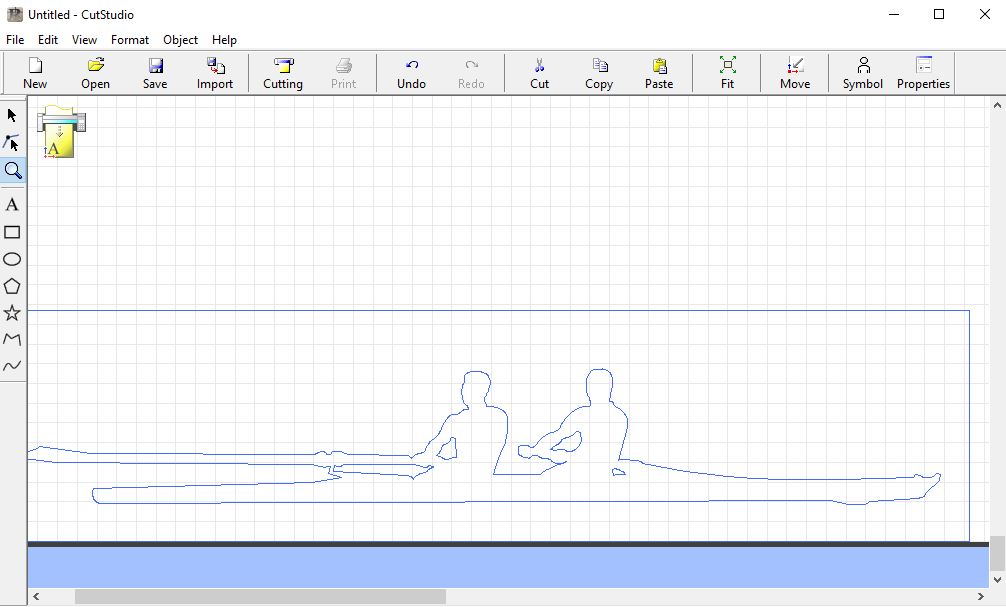
Extracting the outline
I Imported the picture in the CutStudio Software, then extracted the outline by right-click on the picture and selecting extract outline, then I drew a square around the outline of the picture then removed the picture from the software leaving the outline and the square only.
then changed the size of the print.
Then pressed move from the task bar to make the origin at the corner of the drawing
then I setup my vinyl cutter (you will find a good tutorial on how to make it Here )
The First failed trial
I tried to Cut it by force=20 and speed= 15mm/sec
It was so bad but I've known that the force should be around 90 and the speed have to be much lower than that.
It was not cutted as shown in the picture.

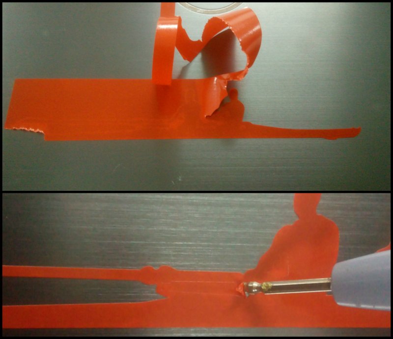
The second trial
I changed the cut speed to be 1mm/sec and the force to be 90 and It was successful
you may need to open the picture to see the cutting lines

Extracting the needed part
You have to be Careful and patient while extracting the needed part.