Materials, tools and software
Epilog Zing 24 (Tools)
Cameo (Tools)
MDF 3mm (Materials)
Autocad (Software)
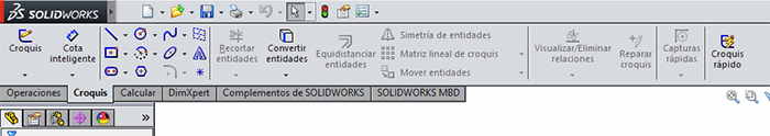
Solidworks (Software)
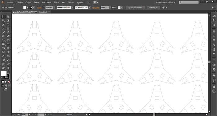
llustrator (Software)
 |
 |
 |
 |
|---|
Epilog Zing 24 (Tools)
Cameo (Tools)
MDF 3mm (Materials)
Autocad (Software)
Solidworks (Software)
llustrator (Software)
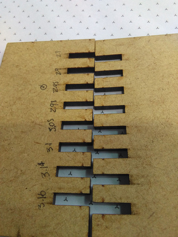
In the first part the group designed a piece for determine all size of the press fit for the application in the different projects of the week.
I make the design in two different software:
With design the new project I take ergonomic measures and make a bidimensional object with press fit, make a scale model in the cutting laser.
I did resistance tests.
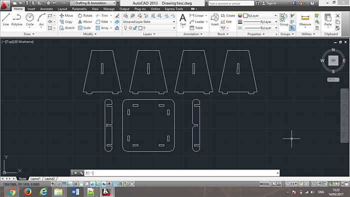
For the design in AutoCAD 2D tools were used to generate the figure inside the main element with the line tool to create the outline of our figure.
The use of this tool in AutoCAD is used based on the dimensions and measurements on the desired measures for the design of ergonomic, anthropometric
tools.
The following tools to generate a two-dimensional drawing were the arch and Fillet tools for the curved parts of the files.
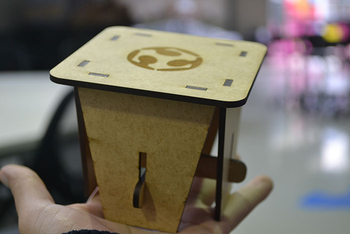
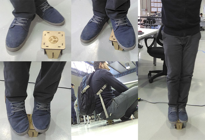
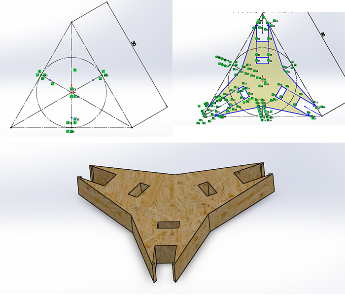
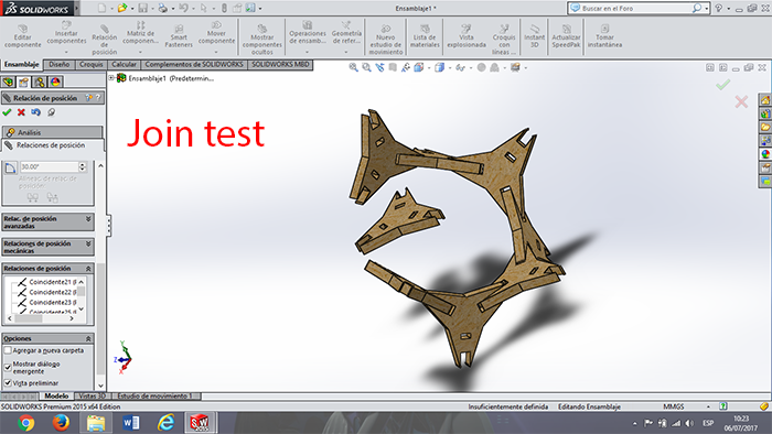
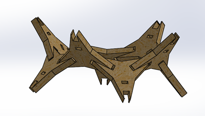
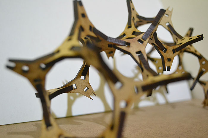
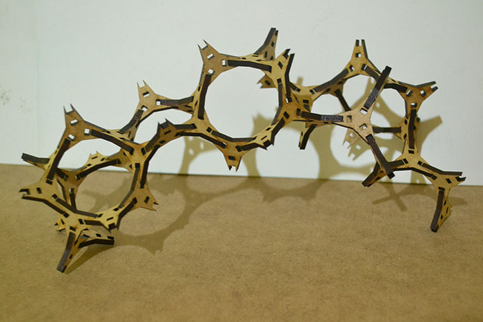
I design a prototype for the stand of FAB LAT in Chile for Fab13.
This prototype is a modular piece but this join can make any position and different alternatives of this pieces.
To make this piece, I use solidworks in 2D design, I make a simulation of the join test and I import to PDF to
make the test of the size of the pieces.

To model the piece I create a plane and use the 2D tools like line, polygon, trim. Draw the sketch with the different tools of 2D; see more information about this software in the WEEK 2. To create the restriction of the sketch using the smart dimension to make parametric design and change the configuration of a piece of the material or the machine configuration.
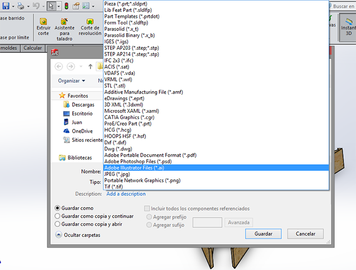
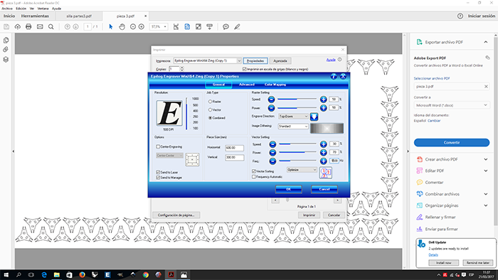
For make a cutting in the Zing. I generate a PDF file, select print, and put the configuration in the machine.
the only limitation is the size cut of the machine
MDF CUTTING CONFIGURATION:
Horizontal: 600
Vertical: 300
Speed: 30%
Power: 70%
Freq: 1300Hz
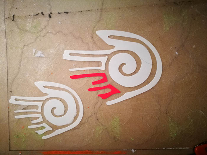
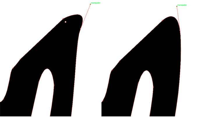
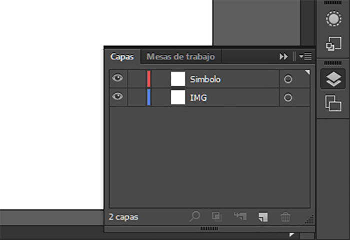
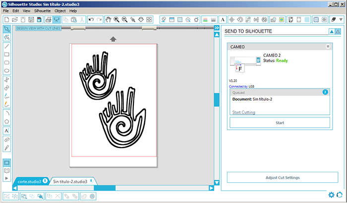
For the design Illustrator was used to redraw a pre-Columbian symbol of the Jama Coaque culture which represents the law of reciprocity, this symbol was one of the proposals for the logo for the redecorative of fab labs. In the design the pen tool was used, by means of this, an image of the symbol and the use of layers is proceeded to redraw the symbol by marking points with the right click of the mouse with a click a point is created and keeping this pressed you can create a curve between two points.
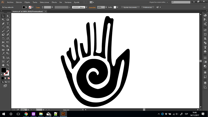
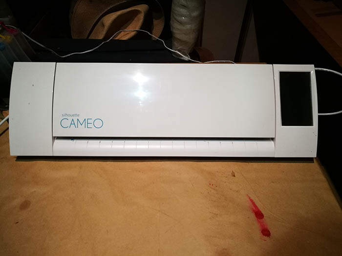
To vinyl cutting use the Cameo small machine and Shilhouette Studio software. To this file, I make a pre-Columbian
design with represent the union of people.
In the next image can see the configuration to make the cut.
MACHINE
SOFTWARE
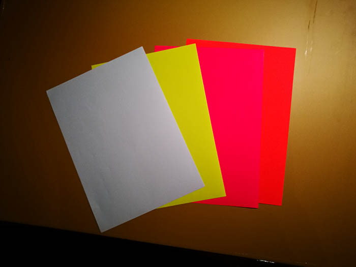
MATERIAL
CUT