Materials, tools and software
Autocad (Software)
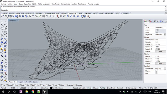
Rhinoceros (Software)
SolidWorks (Software)
Meshmixer (Software)
 |
 |
 |
 |
|---|
Autocad (Software)
Rhinoceros (Software)
SolidWorks (Software)
Meshmixer (Software)
For the Fab Academy, we will use deferments software's but this depends on the application and the necessity.
We have different programs to the applications of the all machines. In the assignments can see the bounding
between the program and its application to a specific machine.
We can find different programs with different ways of working and application in modeling 2D, modeling 3D,
rendering, Simulation, etc.
I use SolidWorks because is a software for macanical design and is the necessity of my final project.
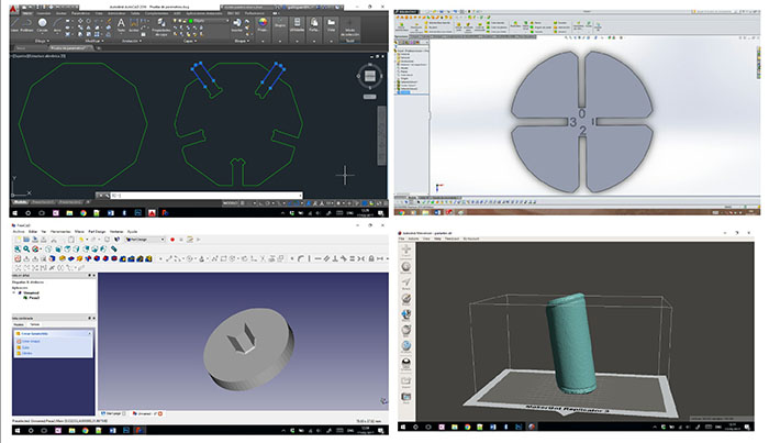
In my final project, I design a Ceramic 3D printer, for make this I use SolidWorks because is software for mechanical design development.
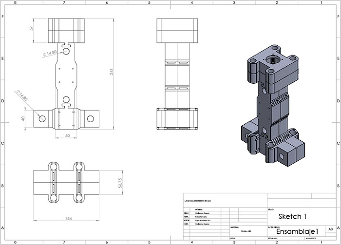
For this part, I modeling the first sketch in 2D and 3D in solidworks.
To make the modeling process, I use the sketch to make the 2D plane of the pieces with restriction to can change the size.
Them I use the 3D tools to make the complete pieces.
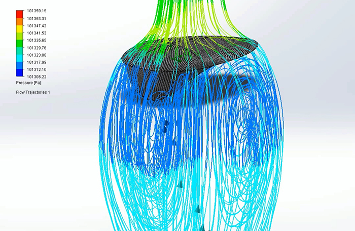
In this software, I can make any process for modeling, rendering and simulation of the different parts of the machine.
I generate a file technic when we can the first sketch of the machine in 2D and 3D, a simulation of and rendering of the join
to the final pieces.
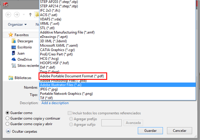
In this technic file, I export to PDF or in a different format to make the pieces.
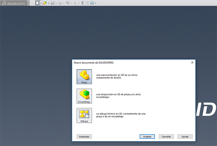
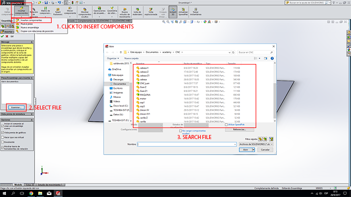
The first think to know about the software is the three different files types this has
1._ you can design a PIECE in two or three dimensions according to your need.
2._ is the ASSEMBLE; you can join two or more pieces.
3._ SKETCH is a data sheet of a piece or an assembly.
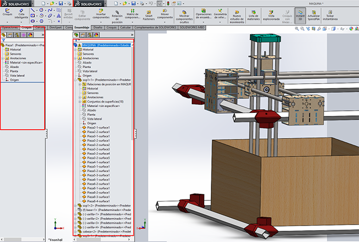
once chosen the type of file opens the window for development of the project in this case we chose to make a piece, at the top you will
find the different toolbars to work in 2D, 3D or different processes such as simulations, renders or other.
Another detail to the left of the program is the window of process flows that we make along the modeling of the part in which we can repair, edit or eliminate the different processes observing how our design varies.
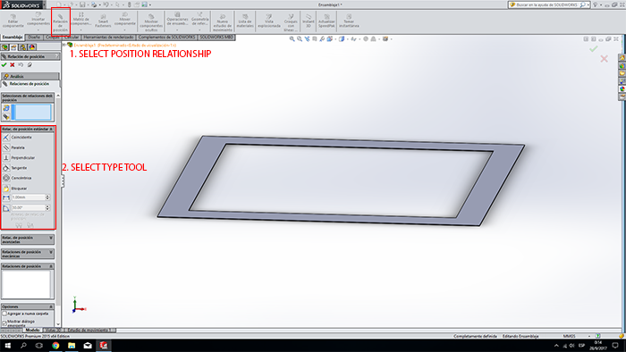
For the use of this complement all, the pieces to be used are modeled. For a simple use of this process, the parts are aggravated and relations of position are generated based on the union of their designs.
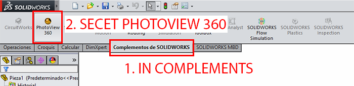
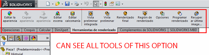
To make a render in SolidWorks is very easy, first select the materials of the pieces to the right we can find the appearance button in which we have a wide catalog of different types of materials in which we can add our piece. Them use the RENDER TOOLS, which we find in the add-ons window and selecting PhotoView 360, and select a FINAL RENDER button.
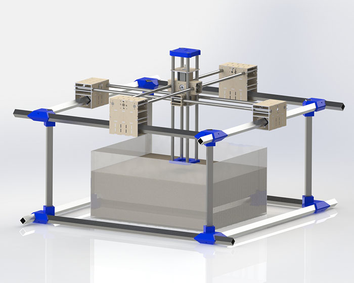
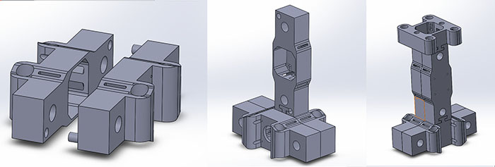
Based on the position restrictions mentioned above, we could generate the movements generated by the design in this case, the passage of the machine head over the guides.
can see all the process in the desdescription
The old files can take in the next link in drive
The new files can download here