Solar panel as Input device-final project board
In this board i am going to use solar panel for my final project I design my own board in output device with eagle and in this I mill that board and solder it. but its programming is remaning because of its some input data so now its time to collect that data which is required to set the code for the solar panel
1.collection of data in sd card -in this I use the aurdino board and sd card reader module I want some voltage calculation of solar panel so for that I make one small home and on its roof I put the 2 solar panel with some angle and I connect its one positive to the analog input i.e A0 and A1 and I make ground common then I connect the sd card module the code on it
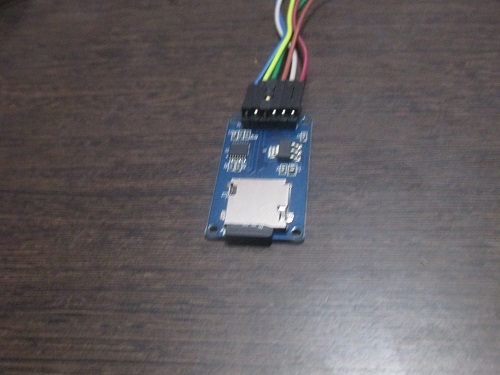
this is the sd card module it is having chip select pin and we connect that to our board and I set the program there then I will get the continues reading of that.in my case I want the voltages on both solar panel during the whole day for that I upload one program on my controller board
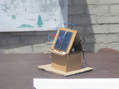
whole day I put this home outside and at the end of the day when I put sd card to the card reader then I get the following data but this data is not divide by 1024 thats why I directly display my data
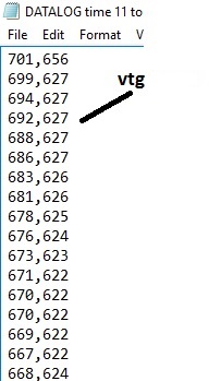
I use this data for set my code according this data I make the code for my final project board
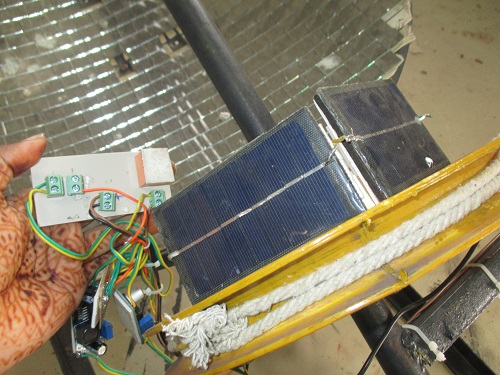
my logic for my code is I bring the solar panel with some degree.I set one value to the delta i.e the most common differnce in that both panel during the whole day .If there is difference in delta then my panel give the signle to the output pin and the output pin connected to the relay. the relay connected to the motor and motor can move the solar concentrator dish
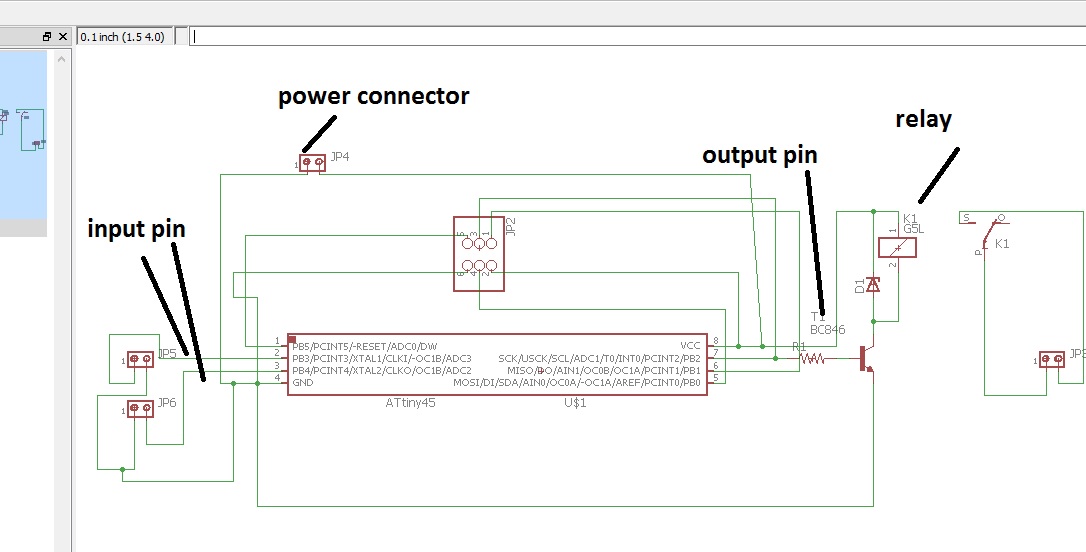
My project is making solar tracker in that i put 2 solar panel for sensor and I take signal from that and according that signal my relay is on and off there for relay is my output board in my final project in this i combine the output and input board together and i design this board .For that first I refer the datasheet and in that I saw which IC i will refer in my final project by looking the port fetures i used the ATTINY45 in my final projectn in this board I required two input pin and one output pin ,because of datasheet i easily selct my input and output pin
first I draw the circuit diagram on paper then i start to design in eagle.In eagle I add the componant Attiny45,resistor,capacitor,then two input pin header and another pin header for output
I open the egal add these componant and join them according my notebook design
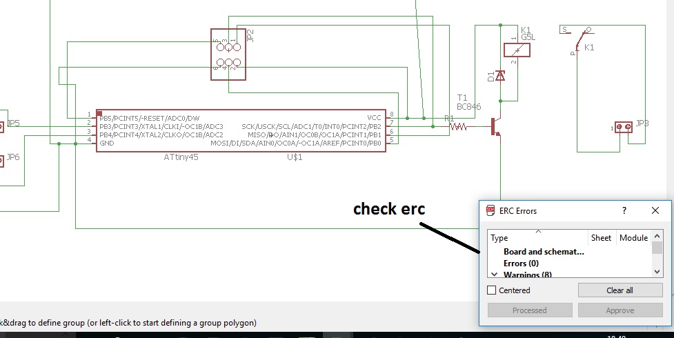
check erc here
switch to board then rearrange the componant and connect them using the wire
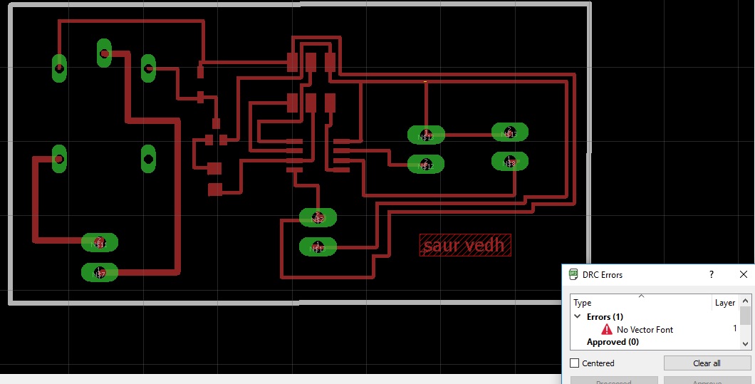
then I check DRC and my final board traces is ready
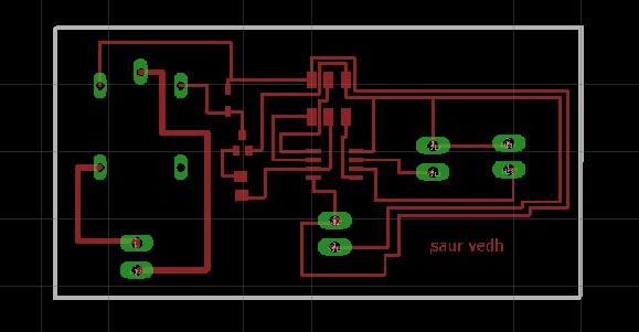
I save this file in .png format
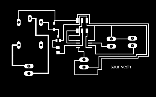

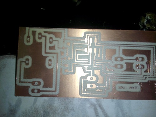
This is my input board traces
Now I mill my Input board,for this I open the fab modules then import the above traces i.e png file
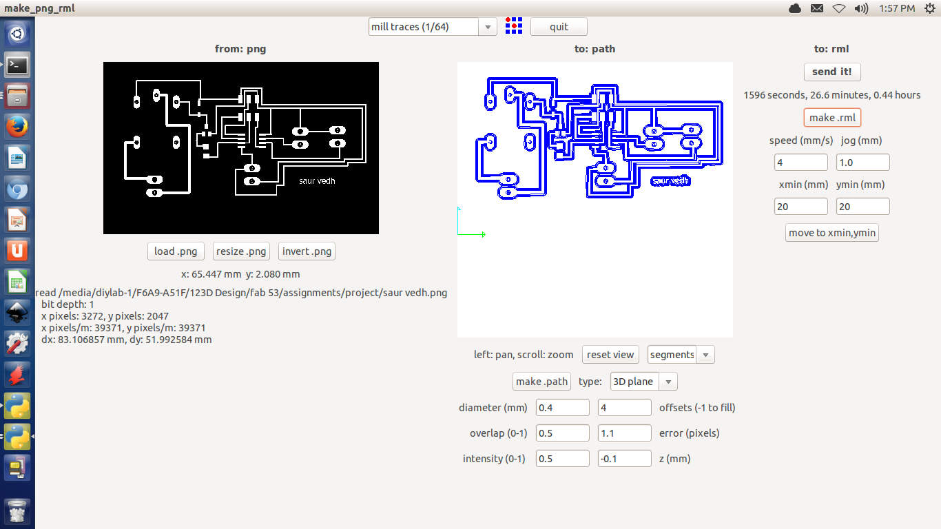
trace the board with 1/64"bit
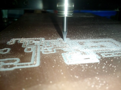
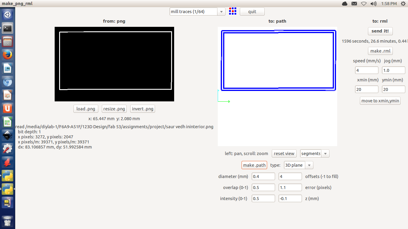
cut the board with 1/32"bit
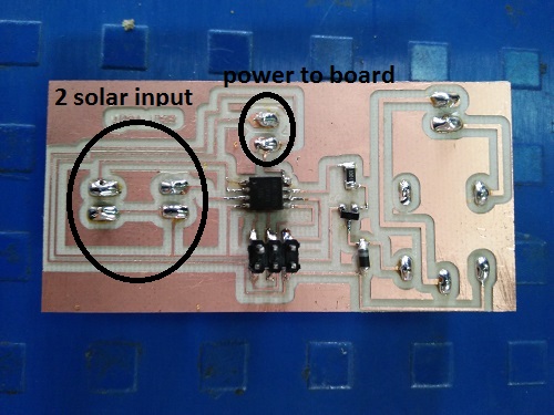
this is my final board
now moving towords the soldring
now I programme my board
As priviously I discuss that I set the input pin and output pin in this board
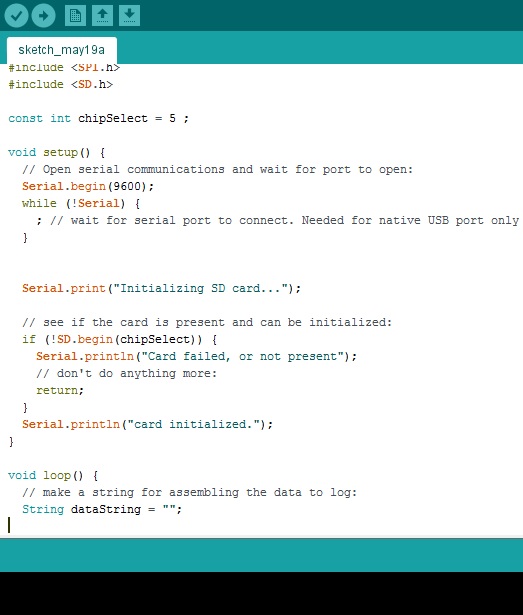
for programming I connect the arduino board to my input device board and I use the arduino as fabisp then I upload code to my board
the serial communication is not run so I make an comment in front of all serial print then my code is uploaded.the code is given below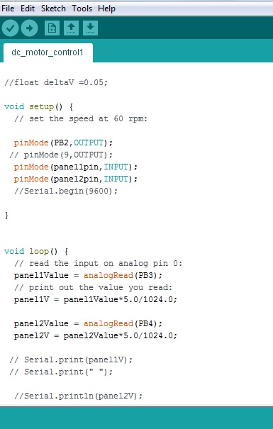
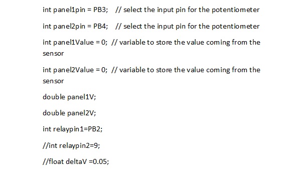
This is my code the below diagrame shows the initial part of code in this I declare here that panel1 connect to PB3 and panel2 connect to PB4.The initial value of panel sensor is zero.Then I set the relay pin to PB2.ATtiny45 is having 8 pins and its 6 pins are i/o pins.
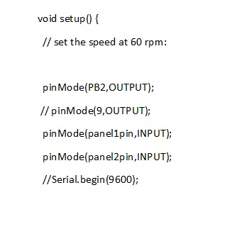
Then I set the above pins as input and output ,in my code I set PB3 and PB4 as input and PB2 as output.Then I set the boud rate
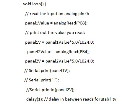
above part is declaration part now actual code is start in this i set there 5/1024 because it comes in voltage form in the range up to the 5v then ,after that I compair the voltage between panels if the value is not equal to each other then my motor is moving until the values are equal to zero then motor stop.In this code first I set the delta but problem with that is if the minor value is set for delta then that panels continusly vibrate.Thats why I make the comment to the delta value other code is same and it succesfully done
Conclusion
one mesure task of my project is finished here that i set my logic to the input board with succesfully testing.in this assignment I learn that how read the sensor data and how the collected information used for the setting the code.