Grashopper file (.gh)
Rhino file (.3dm)
Meet the above goals (first) and (then) construct a laser cut scale model of my final project.
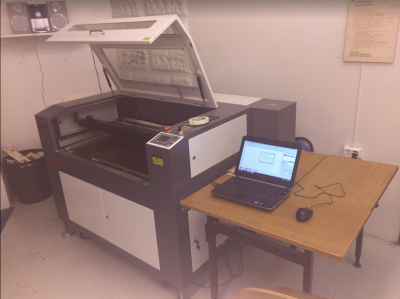
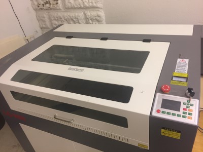
The Verket Fab Lab LG-900 100W laser cutter and laptop running windows with the RDCAM laser cutting software.
Laser cutting and engraving works by shooting a focused laser beam onto a material while at the same time blowing air onto the target spot. The laser heats up the material in a tiny spot so that it turns into gas which the airflow removes before the surronding material it catches on fire. If something goes wrong the material can indeed catch fire so a laser running a job must be under constant supervision.
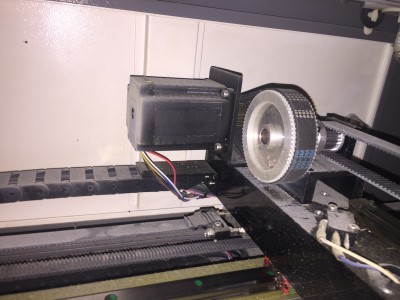
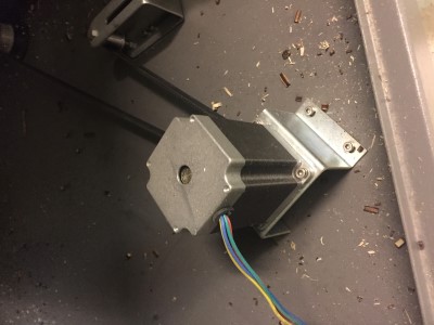
Stepper motors moves the laser head using belts and another one raises and lowers the work surface using ballscrews to adjust the focus distance to the laser head.
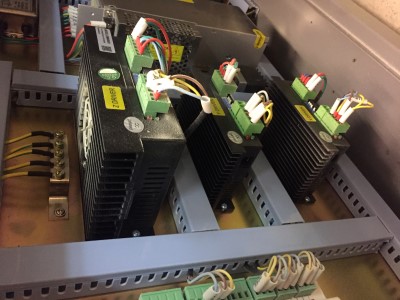
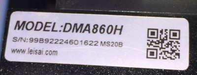
These are the stepper driver electronics "under the hood" of the laser. They read digital signals from the control board and output high current in the correct pattern to drive the stepper motors.
In order to build anything out of cardboard we first need to make some test pieces to figure out a got press fit. We will probably use a few different thicknesses of cardboard so it makes sense to desing a simple to reuse small test piece.
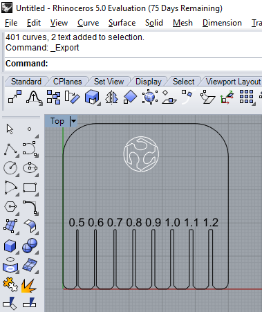
I drew a simple test part in Rhino for thicknesses between 0.5 mm to 1.2 mm. (Perhaps I should have measured our cardboard first...) The commands for chamfer and fillet were easy to find (just type them in). I added a 1 mm chamfer for easy entry and a radius 0.25 mm fillets in the internal corners to increase strength.
I google image searched and downloaded a fab academy logo in .jpg and made into vectors in inkscape using the trace bitmap command.
The first version test piece
Rhino file (.3dm)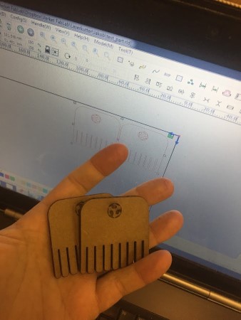
First cut! And yes, I should have measured the cardboard we have available first, it's much thicker than 1.2mm (my widest cut.)
While learning the laser I noted down some possible updates to the instructions in the lab:
Cardboard cut speed was 50 mm/s at 70% speed (Soruce:Oral tradition and folk memory). I will attempt to log the feeds and speeds in a more accessable space.
TODO: Get test-patterns from Bitraf or recreate. Alternative google or ask around.
Collaboration for test piece nr 2 with Hanne! We sat at the same PC and figured out how to scale up my initial test piece and how to get the text to become a curve. Solution: Turn on points for modifying the curves worked great, together with scale to enlarge all the slots at once. The TextObject command can output text as curves.
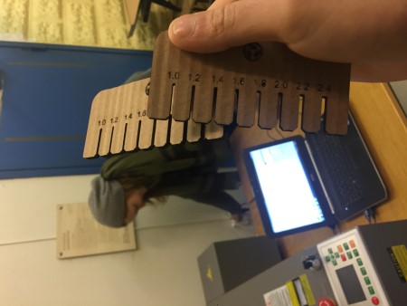
Test 2 with 4 mm cardboard. Slots 1-2.4 mm not including kerf! Measured keft with calipers to about 0,3 to 0,4mm (0,15 to 0,20mm on each side) in cardboard. We mixed up the cardboard so we tested on a different one compared to the one we designed the test for. The largest slot, 2,4 mm gave a good grip but sometimes damaged the cardboard. Noted that I should use less steep chamfer at entry.
We found with some trial and error that the .ai export format works better than the standard .dxf format. .dxf polylines 2004 seems to work as well.
Grabbed some new cardboard from a huge sheet that was on a plywood pallet. Nomial thickness 2,6 mm. good grip in 1,6 slot when structures are coaxial. 1,4 works as well, especially since my test piece quickly wears in, however the cross "grain" insertion resistance is more than I like. I'll stick with 1,6mm gaps for now. interesting note, could experiment with pinching bottom of the hole to lock it in.
It would be fun to do something creative.
Ideas so far:
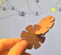
My idea is to cut "leaves" with slots that then are assembled as a molecular crystal structure. Please note that I know very little about crystal structures so I might be completely wrong. In other terms, I want to make something that looks structured in three dimensions.
I designed a parametric curve in grasshopper mostly by guessing node names and reading their help-text. I also peaked inside the (bark-beetle from fellesverkstedet) plugin that I had loaded in grasshopper for some reference code. See also week2 for my first steps in rhino and grasshopper.
TODO: play with "Evaluate" as a more flexible math tool.
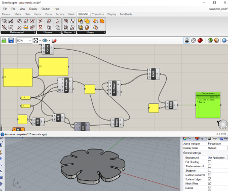
Here I extruded the curve to see it better.
Grashopper file (.gh)
Rhino file (.3dm)
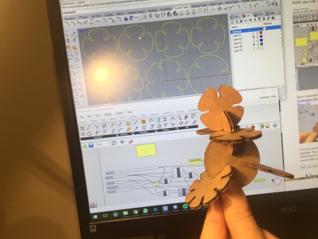
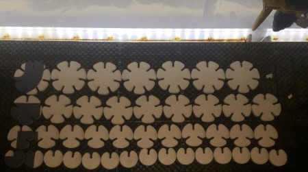
I cut two prototype pieces of my 8 leaf design. Turns out it is easy to accidentally damage the leafs when pressing them together. Since I want to be able to build large delicate structures I'll increase the gap to 1,8 mm for the next batch. I also noted that it was beneficial to rotate the "grain" of the cardboard to not align with my slots. And finally, the fillets worked much better than the chamfers for easy entry!
Something is not working perfectly with my fillets. Sometimes it fails to round all corners. I tried applying it twice with no luck. I raised this issue with Jens Dyvik our instructor and he has since then confirmed that it is a Grasshopper bug and sent me a suggestion for a workaround, I look forward to looking into it.
A comment on Rhino+Grasshopper as a parametric design tool. This is much more programming than traditional parametric CAD (Solidworks etc). With that comes some additional freedoms but the workflow is so much slower. A record-macro function would be so awesome!
New cut, tried 80mm/s 70% in 2,6 mm cardboard. Worked fine! They fit just fine and does not break during assembly, however the force required to fit them is unnecessarily high. I'll go even wider next time (2.0mm). Also it is not technically a parametric "kit" just yet, it is a parametric "part" which I copied out to a kit.
I made a parametric construction kit by creating several "clusters" (functions in other programming languages). One for generating a part with a variable number of leaves. Another to place an array of copies of at the correct height and of the correct length. Then I chained them together and packed it all up in one neat cluster.
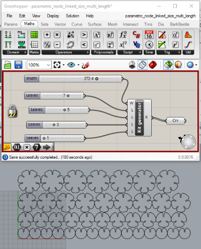
Exported and cut!
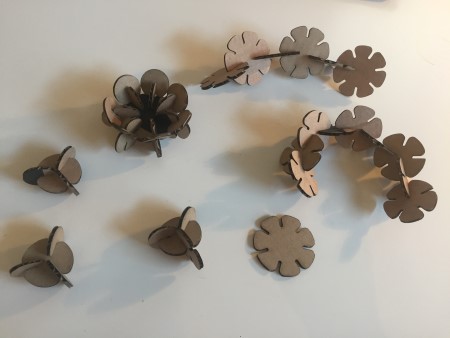
Assembled!
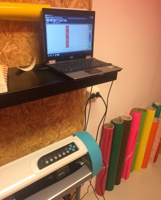
The Verket Fab Lab GCC AR24 vinyl cutter and windows laptop running the GreatCut cutting software. The vinyl cutter uses motors and rollers to moves a knife blade side to side and feed the vinyl film in and out past the blade. This way you can cut contours of one film material at a time. It's typically used to create "stickers" and is a practical way to apply graphics to complex surfaces like cars doors.
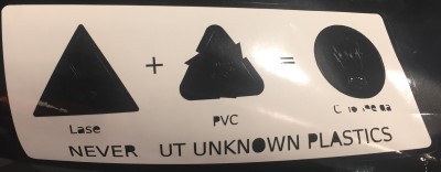
For this task I wanted to make something practical. I made two signs for the laser cutter in the lab. I compiled them in Inkscape using free graphics found on the web.
It is important to never cut unknown plastics in the laser cutter. Cutting PVC (polyvinylchloride) aka "Vinyl" will release chlorine gas, which is not just poisonous but reacts with the moisture in the air to form Hydrochloric acid which will corrode the machine and quickly damage the optics.

I was taught to use the standard settings for this type of vinyl and have not experimented further.
The first cut got damaged when the vinyl sheet ran out at the last 50 mm of the entire cut. However I could use it for practicing picking out the letters. I learned to avoid having to clean small details like the holes in the gas mask and that small details like letters are better made as holes.
I have not made the final application of this sign yet since my local classmate is working on the sign it will be transferred to.
UPDATE: The sign was never finished so I never transfered this design. However I noticed that the dots in the gas mask filter and the concentric circles in the eyes was annoying to pick clean. For my next design I will reduce the amount of small details so that it is easier to transfer and clean.
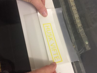
It's easy to forget to turn on the fan for the laser cutter, this sign,reminds the user to remember to turn it on.
The Verket Fab Lab laser cutter
Reminder sign in norwegian, made in Inkscape.

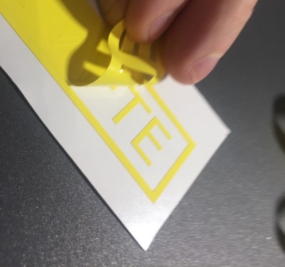
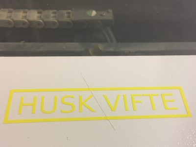
I first cut it in yellow vinyl, cleaned it and used transfer tape to apply it to the laser lid. However the color did not stand out very well. I decided to cut another one. I switched film to a black one and successfully used the same settings as before after testing them with the "test cut" button on the machine.
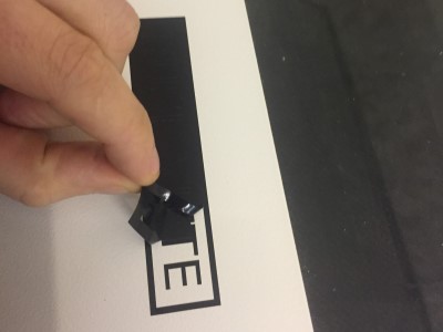
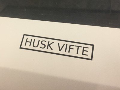
This time I did not clean up the cut but instead transferred the whole piece to the laser lid before picking out the vinyl skeleton. I think I prefer this method, I think it reduces the risk of dislodging small details. Compared to my first experiment this has bigger text and that reduced the complexity a lot.
The black text was much easier to see! I managed to place it a bit crooked but the message will get across!
Transfer the whole design to the target surface using transfer tape and then remove the skeleton.
It is faster to remove a background, leaving details like letters behind, but this can cause fine details to move. In reverse, removing many fine details to leave holes can be time consuming. Choose the one that is best for your design.
To make skeleton removal easier, draw a box around individual words so that you can pull away a small skeleton for each word instad of having to peel a huge one that might catch in multiple places.
Avoid, if possible, having many small details like the dots in the gas mask filter above.
Do not rip the skelton away like a band aid, take your time and use tweezers for the details.