
The assignment for this week consisted of redraw the echo hello-world board, add (at least) a button and LED (with current-limiting resistor) check the design rules, make it, and test it. Using the knowledge acquired previously, we made the design of the board which contained a button and a led, after downloading the software and libraries, we can approve it and run a test with Arduino and check its implementation.
ATtiny45
1 uF capacitor
10k Ohm resistor
Pin headers (3x2 and 1x4)
Green led
499 Ohm resistor
Switch
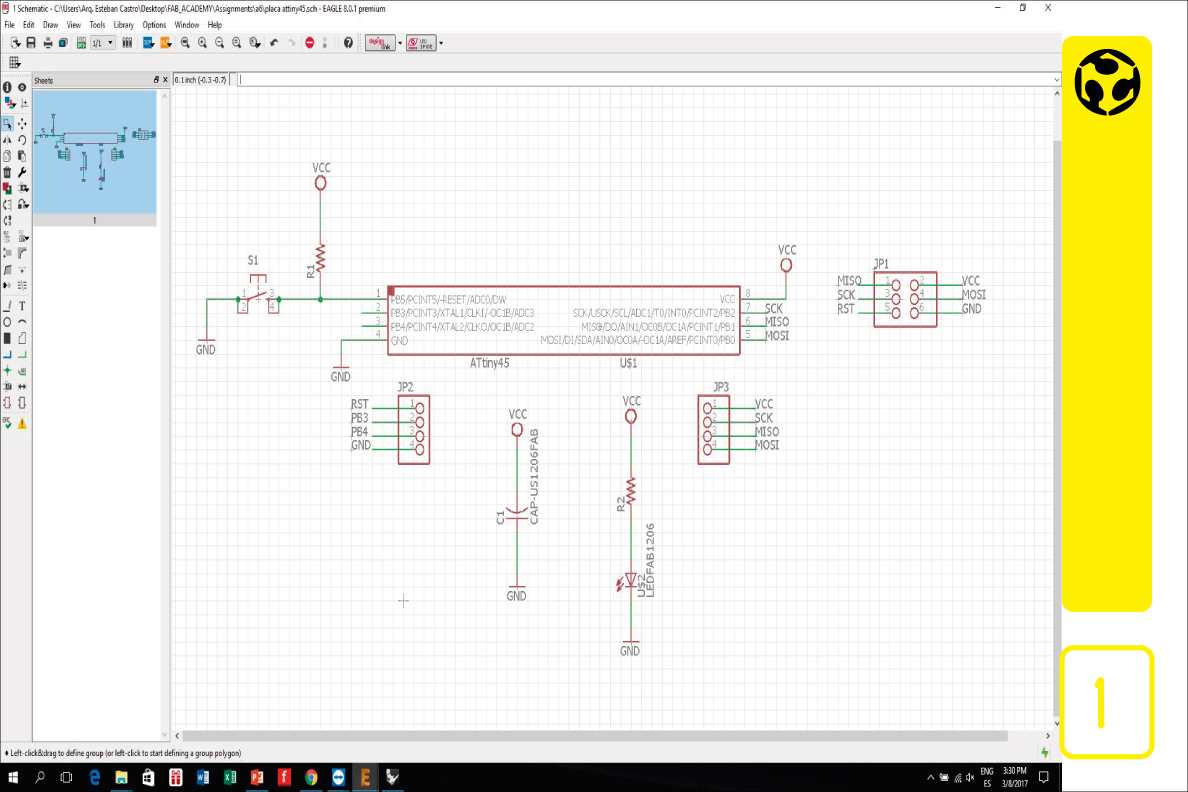
1. We started drawing the schematic (eagle software) for the board, first the microcontroller, then other components and the pin headers for programming and connecting to a circuit. When we finishe the schematic, we added a button and an led to the board. Since we will need the free pins to use as input or outputs for later circuits, we decided to add the led as a power indicator, and the button as a reset switch.
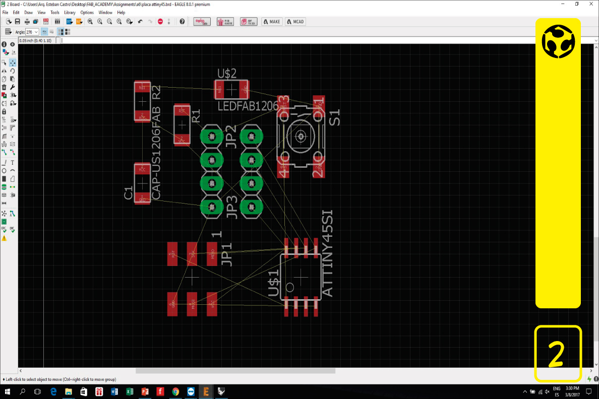
2. We change to the schematic view.
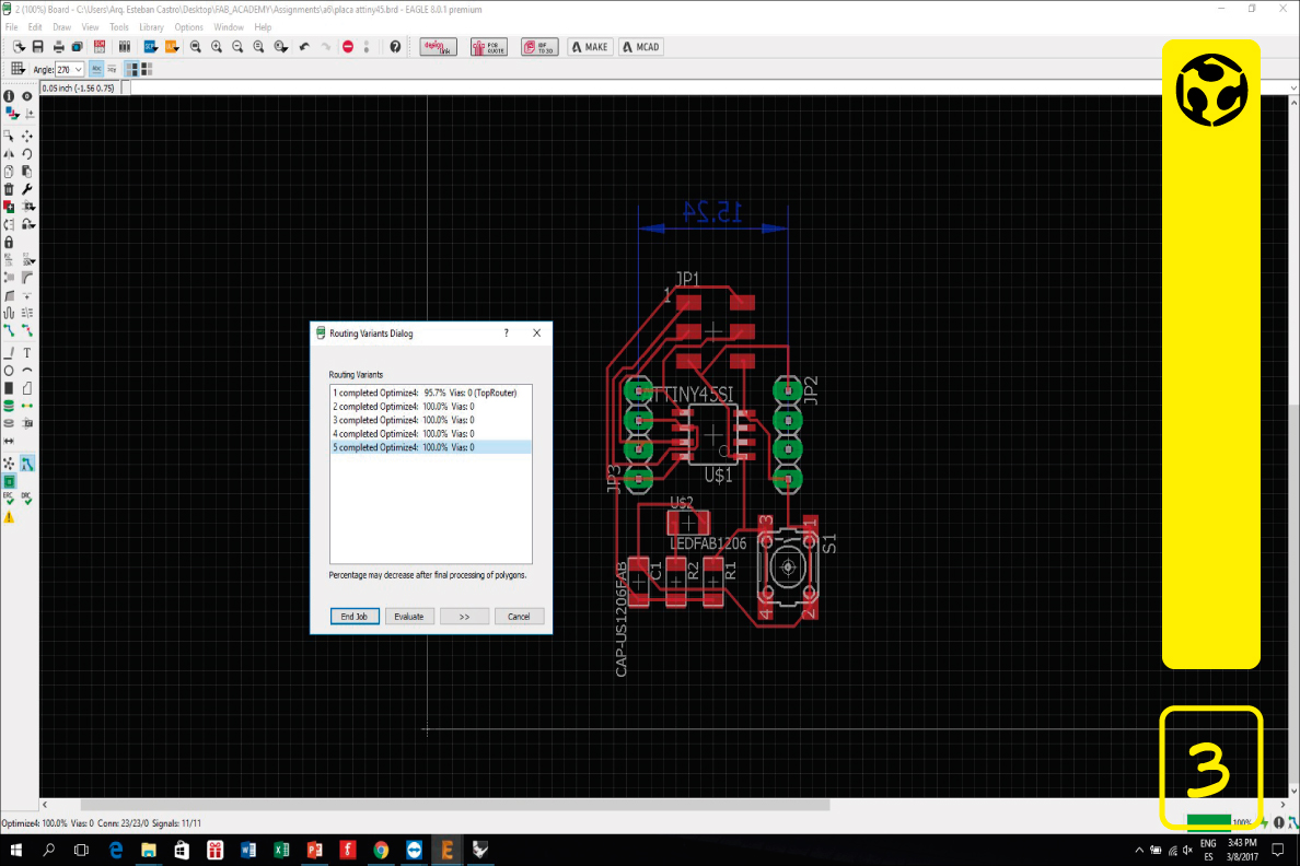
3. We run the autorouting so that the electronic phats are realized.
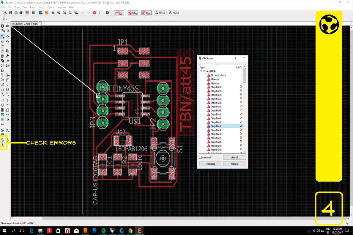
4. We look for errors to verify if the card is correct and to correct what is necessary.
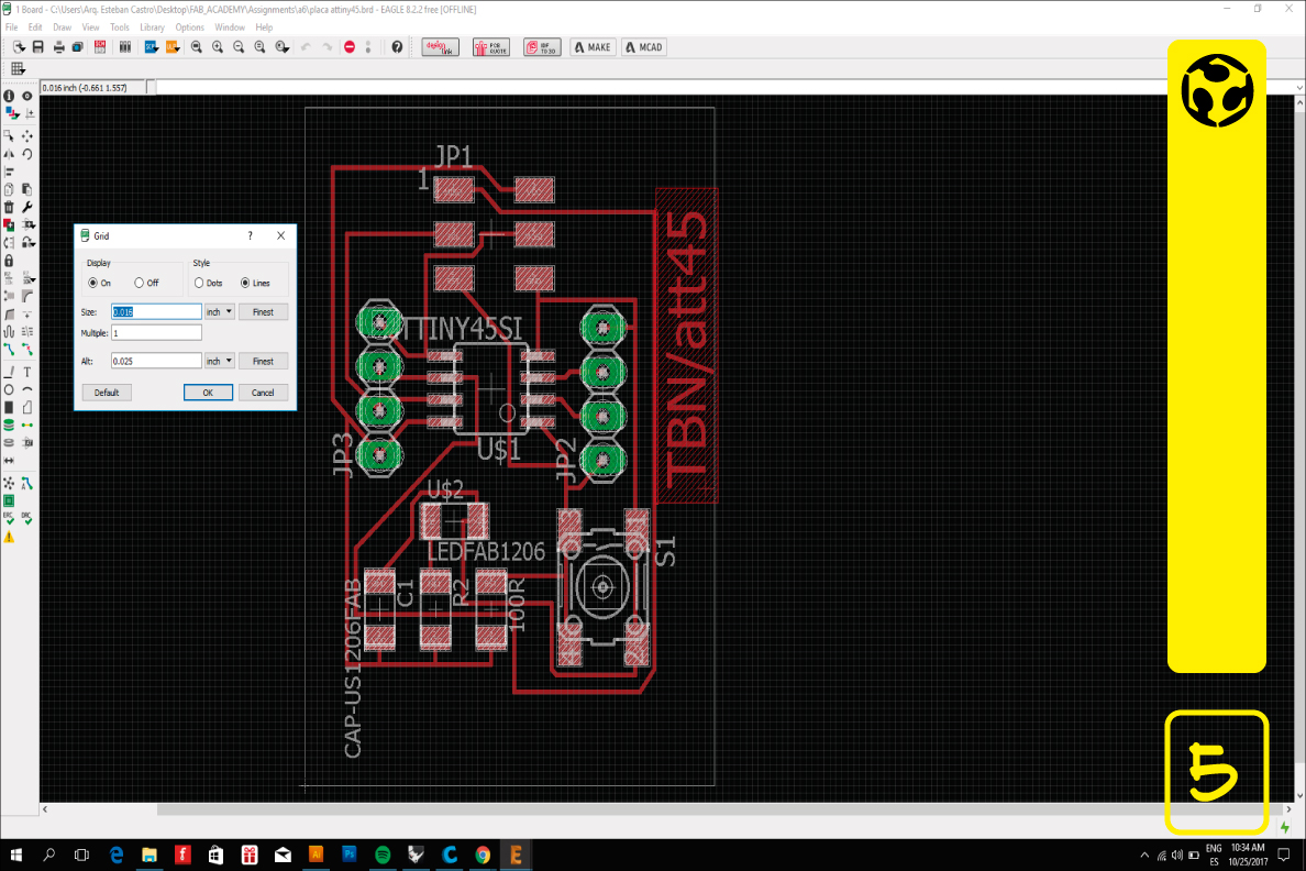
5. To ensure that the tracks fit the milling cut size, I changed the size of the grid to 1/64 inch.
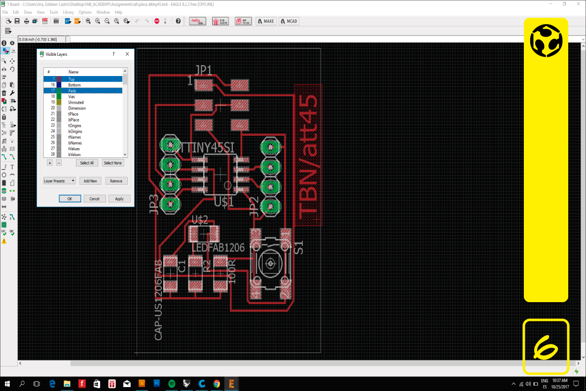
6. It is necessary to display only the Top and Pads objects to export.
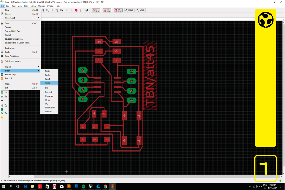
7. Go to menu File / Export / Image
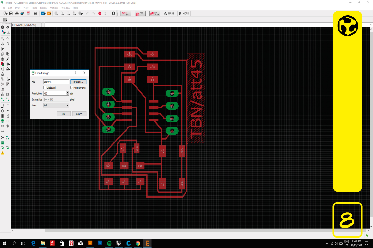
8. Enter file name, check Monochrome and set resolution to 450 dpi.
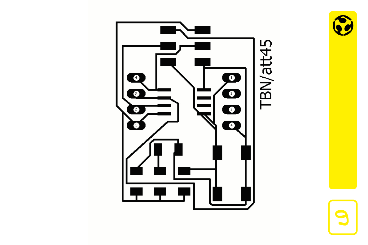
9. This is the PNG file that will be cut in the milling.
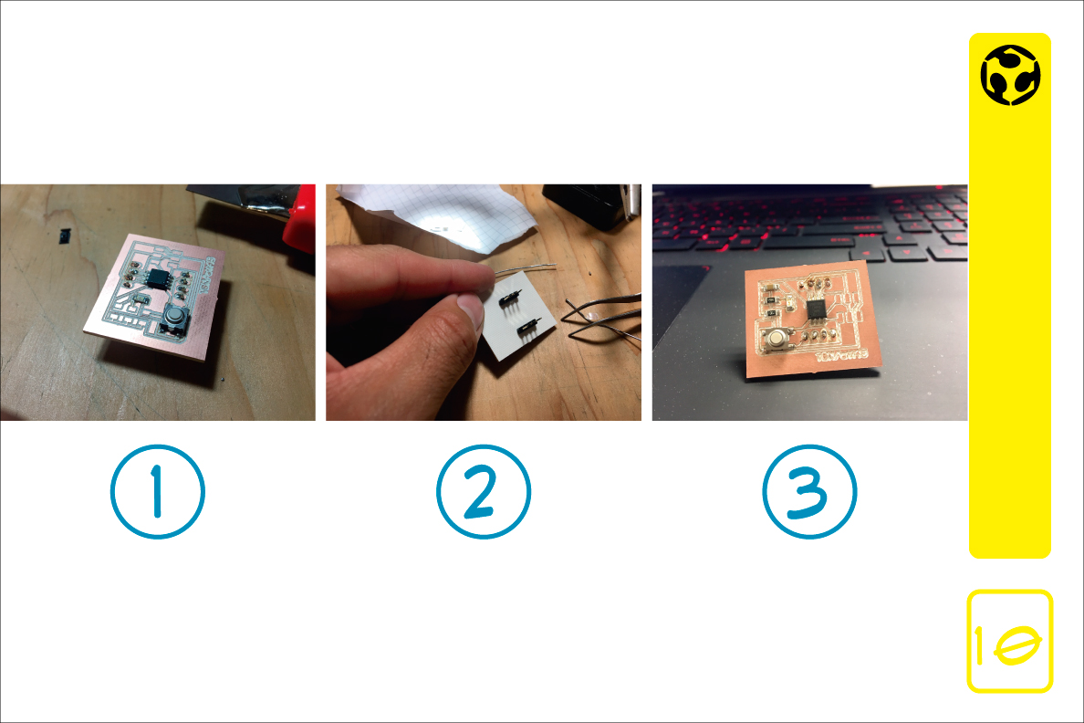
10. Process
1) Select all electronic components.
2) Welding process.
3) Final resault.