
For this assignment we wanted to control a stepper motor 17hd4063 05n using the driver A4988 to learn how to spin it and compare rotation aginst displacement to implement our mchine.
The configuration for this setup has a step pin, a direction pin, vcc and gnd on the microcontroller. The driver has vcc and gnd for the motor (it requires mor voltage and current) and four pins for the motor coils.
When the current is alternated on each and between the coils, the motor moves one step (it can also move in half steps). So the microcontroller sends a series of HIGH and LOW signals, and the driver changes polarity on the coil pins to make the motor rotate.
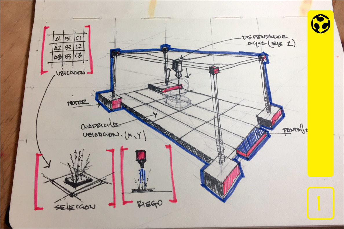
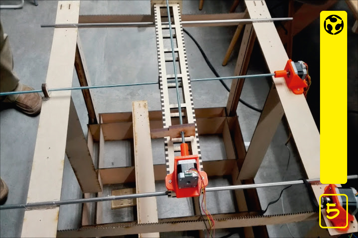
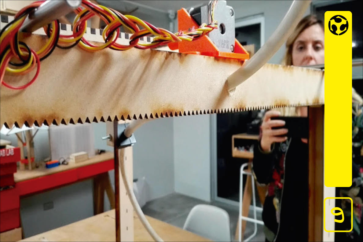
1. The original design used the movement based on CoreXY theory, however we decided to move the X and Y axis by means of worm screws, as it would give us more strength and stability to the mechanism.
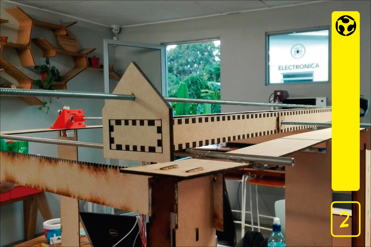
2. The structure was created with laser-cut MDF, some parts were printed in 3D and the metallic and electrical parts were obtained from a discarded 3D printer.
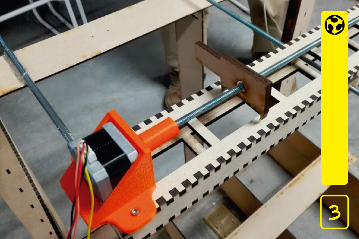
3. The movement is produced by 2 steppers to which we connect 2 screws without end. The control of the steppers is handled by means of the drivers that we obtained of the discarded 3D printer.
4. The first prototype does not use water, we put a third stepper and we simulate that it went up and down a kind of pipe, but the idea had several problems.
5. The main problem was that the movable head that runs on the Y axis, passed over the X axis and therefore represented an obstacle. The other problem was that if we use the Z axis to raise and lower the pipe we need to move the stepper Z or design a mechanism with ropes. The best thing was to adjust the design again.
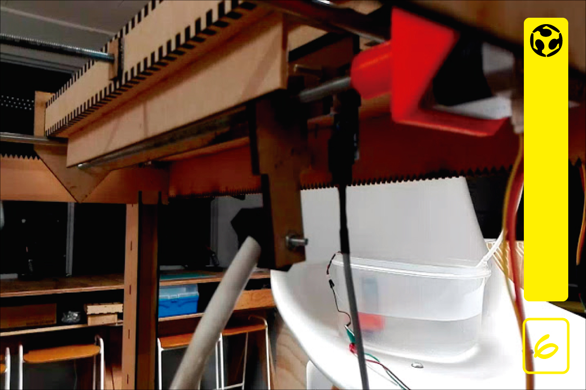
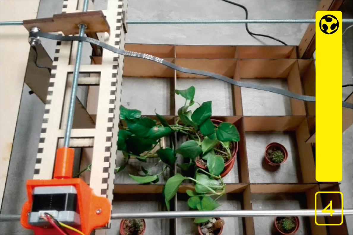
6. The solution was to invert the position of the Y axis so that the screw passed under the X axis, in addition it was decided that a hose would move along with the head and would use a water pump.
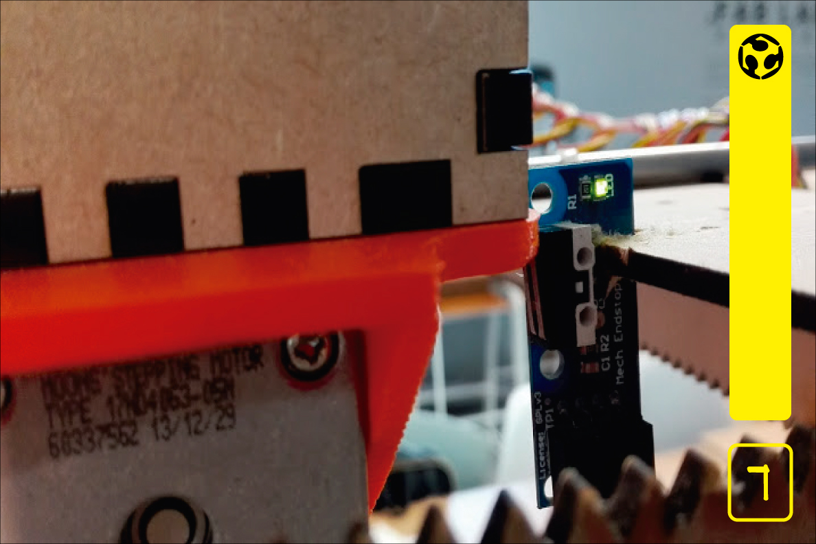
7. Already with the problems of movement solved, we put a indicator of HOME for the axis X.
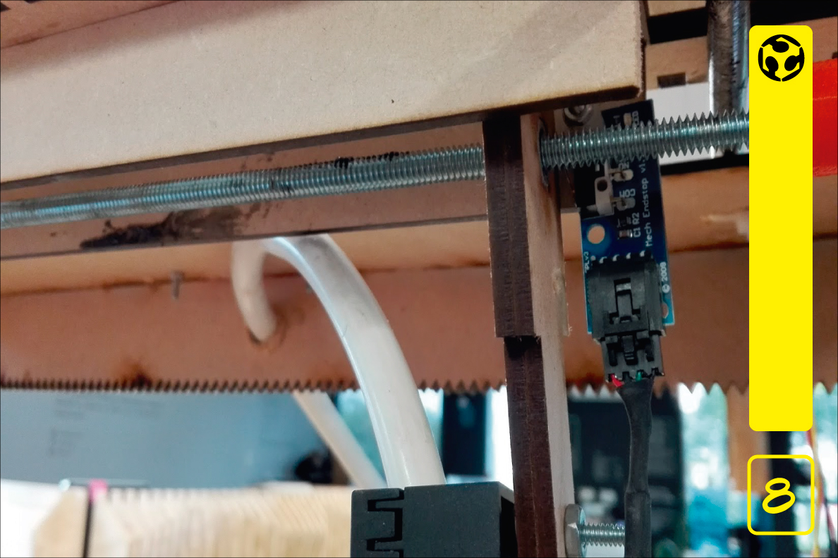
8. We also place a HOME indicator for the Y axis, so we know exactly where the origin is and from there we can calculate the positions of the quadrants that correspond to the plants.
9. The hose enters the structure just below stepper X and is attached to the head that will move through the quadrants.
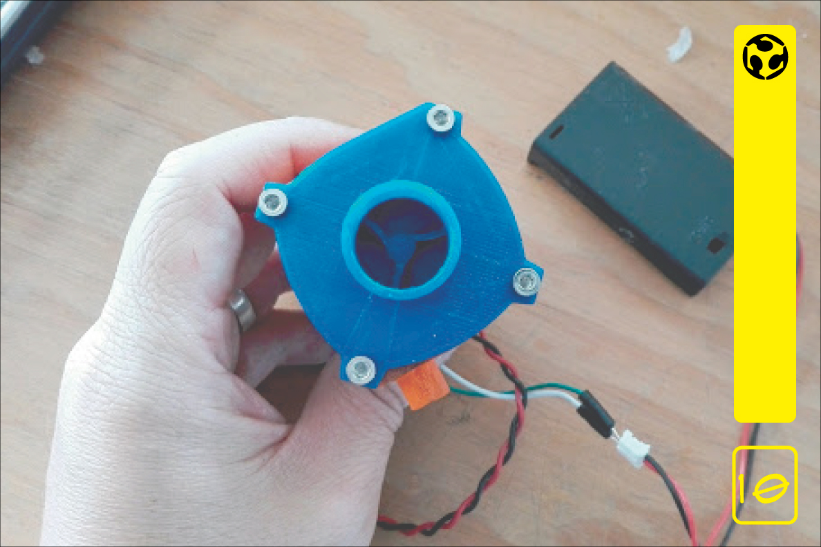
10. We decided to make our own water pump, for this we downloaded a design from Thingiverse.
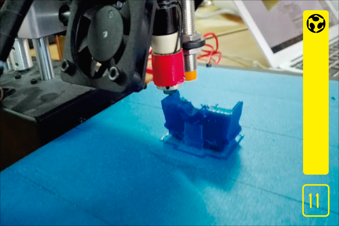
11. We print the parts of the water pump in 3D.

12. We assemble the pump and tested with batteries, for lubricating the mechanism used with graphite grease.
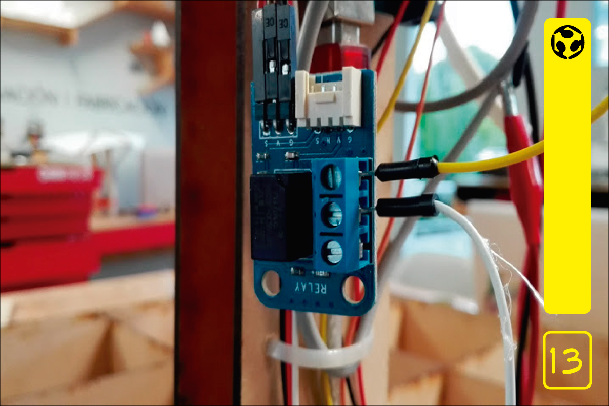
13. We use a relay to turn the pump on and off.
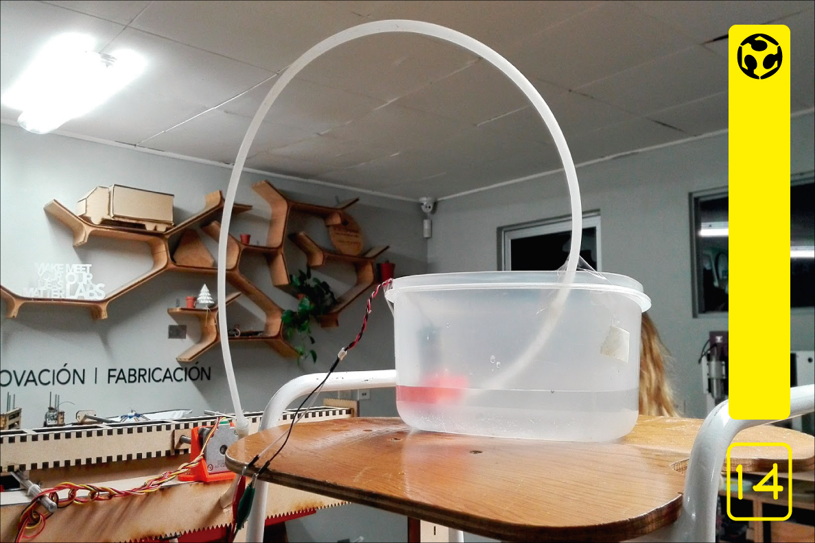
14. Because the water pump is small and has some air leaks, it does not have enough power to push the water if we put the container down the machine.
To see the complete operation go to the group page.
Video Sample