This week we are going to learn how to design a circuit to produce it later
Designing a Cirtuit
This week we had to learn how to design a circuit in software, in this case we used Eagle. This is a software that let us make a distribution of a PCB from an schematic circuit. This kind of software has an autoroute function, but generally this function isn't optimal, so, although it will take more time, ideally yo do it on your own; this will avoid you the posibility that the software order the tracks in such a way that you'll have to put jumpers with cables, and even more important, you will know where did you put the components and what is everything if you need to check the circuit later.
This are the steps:
Create our own components
In the last electronic assignment we realized that we had the wrong 6 pin header but we found usefull the FTDI header to program the board. Because of this we need to create a new component on Eagle, not beacuse it doesn't exist but it will help us to identify the pins that we are going to use in the new header.View larger
Making the schematic
This step is the easier, you only need to type "add", select the component that you want to place, place it and when you have finished, you have to connect them typing the command "net". Sometimes is necesary to look the datasheet of the component to confirm the pinout.View larger
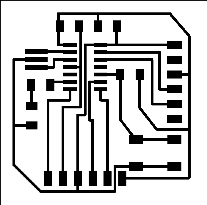
Routing the components
This process is kind of iterative, we need to place the components and start routing with the command "route". With this command, each time we click on a pin, the software will show in red the pin with which it is connected to help us making the routing, I did it manually because with the autoroute function the software put some jumpers that will complicate and get dirty the board. Is iterative because on the way we'll notice if we have to move some components to make easier the connection. We have to be carefull to not route accidentally with another pin with which is not connected, because we could alter the function, or worse yet, damage some or all of the components.View larger
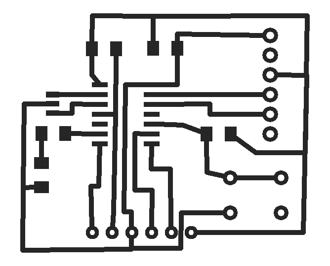
This is the result:
Designing a Cirtuit v2.0
I tried a second software, it is Fritzing and it has a protoboard view and code simulator besides the tools of schematic and board view.
The process is the same:
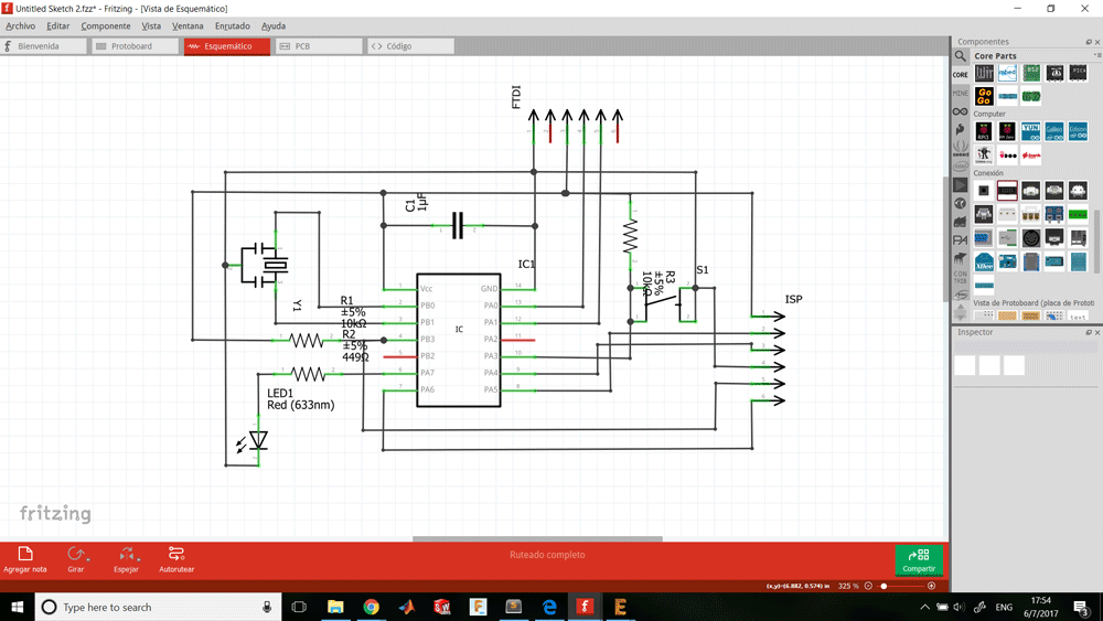
Making the schematic
In this case we have to pick the elements from the right side, they are organized in libraries. Is useful picking generic elements because later we can change its value or its number of pins. So we have to pick and place the component and net the connections. On fritzing pins are numerically ordered contrary to Eagle thare ordered by ports.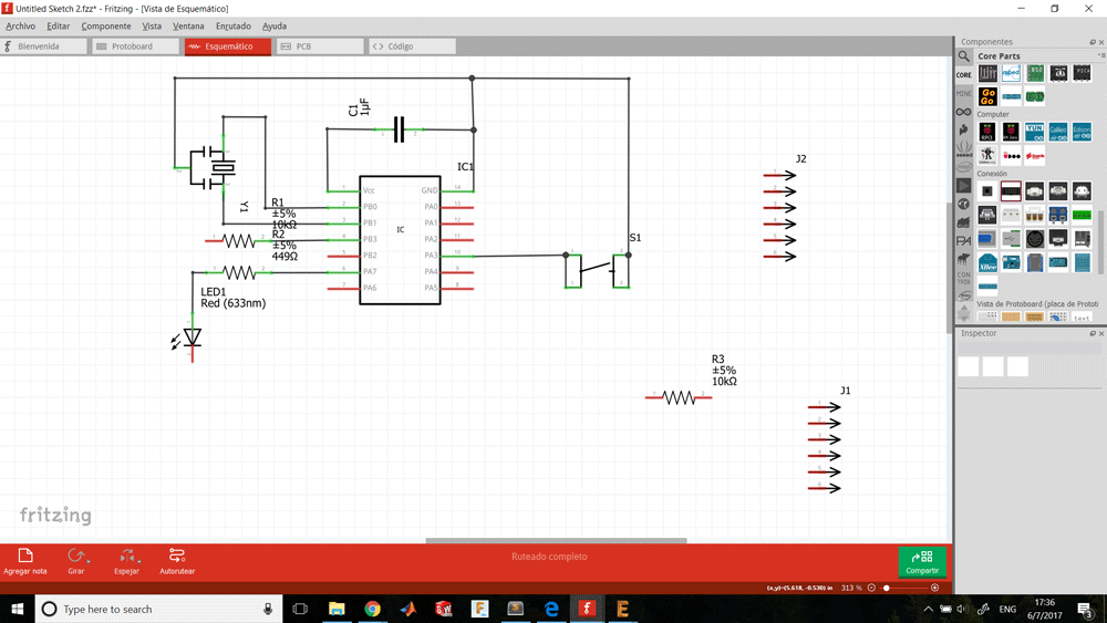
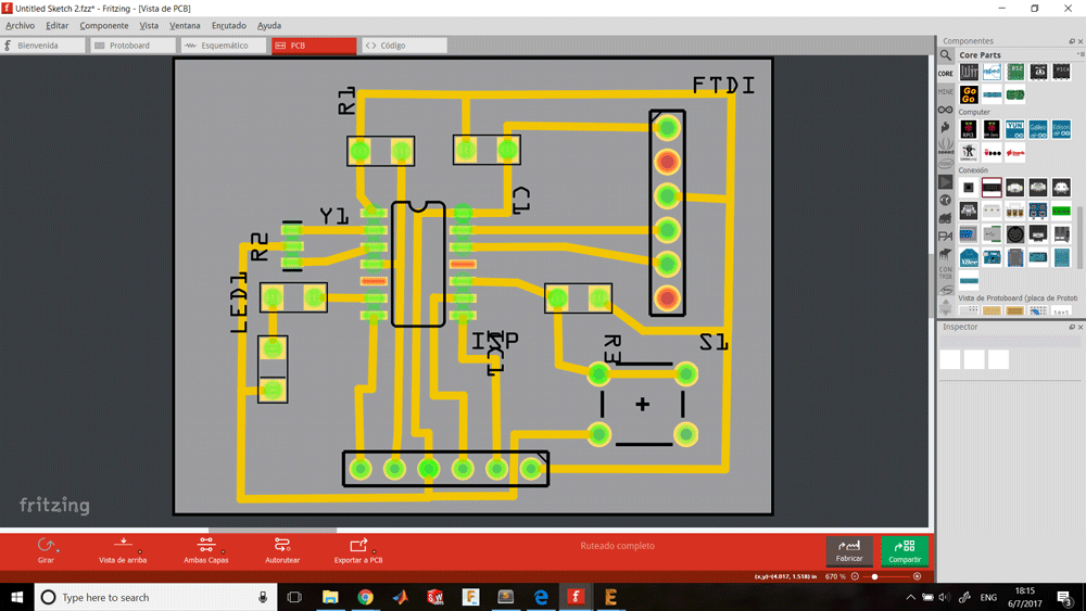
Routing the components
This step is less accurate because the way to distribute the tracks is by the resolution of the grid and it will take a lot of time if you want to place the tracks straight. But routing is simple, you can guide by the ratsnest, click it and a track will appear, then we can modify it and adjust it by putting a node. You can modify component's pads on the menu of the right editing its properties.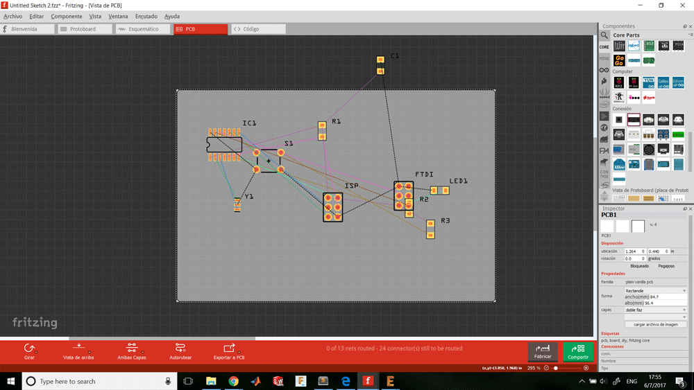
Making the Cirtuit
We changed the week 4 method a little, we have been experimenting and we return to a technique that two weeks ago failed. This time we cut an adhesive vinil stencil on the laser, we stick it on the cooper board and paint it.
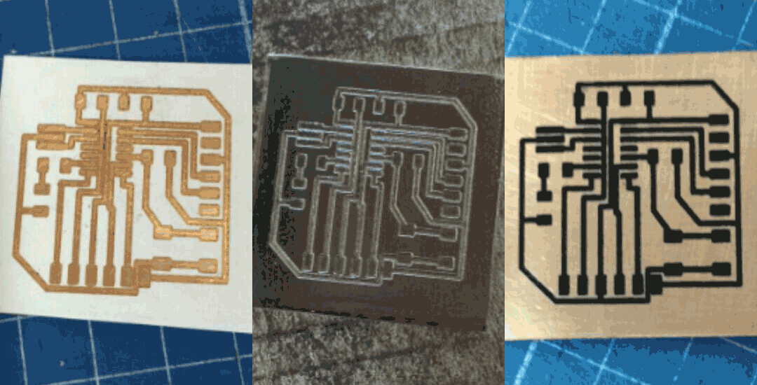
Using adhesive vinil we avoid the cleaning step and go straight to the etching step. During this process you have to alternate between exposing the board to perchloride and oxigen.
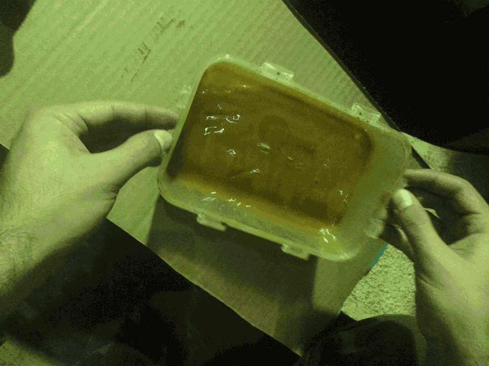
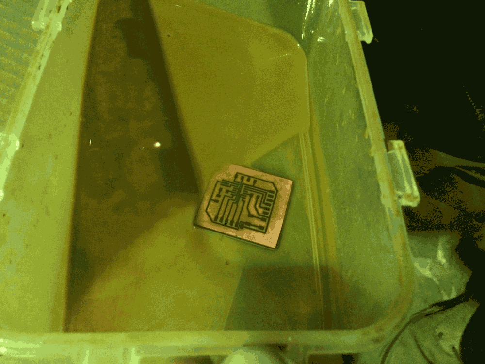
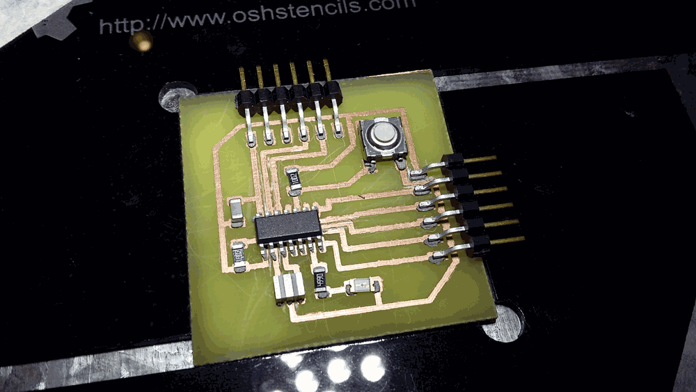
And it's ready!
Sponsors