This week we are going to explore digital fabrication machines to produce electronics
Making the PCB
Classification of electronic components
We received all the components that we are going to use in the Fab Academy’s electronic assignments. We needed to classify and package them separately, and some other that must been package in special conditions, because they are humidity sensitive and letting them expose could mean their deterioration.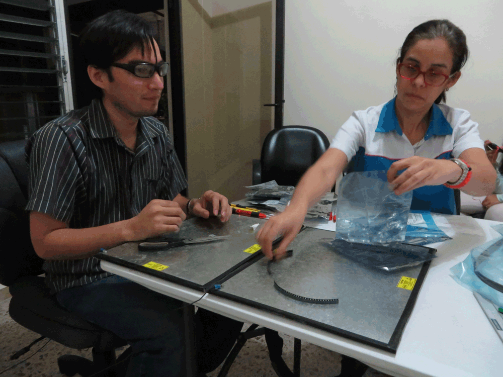
Pure experimentation: PCB vrs Laser Cutter
As we have no access to a milling machine in the lab, we had to fabricate our PCB’s with a different process, so we decided to try with laser engraving as a suggestion of one of the Hackerspace San Salvador staff member.First of all, we based in this tutorial
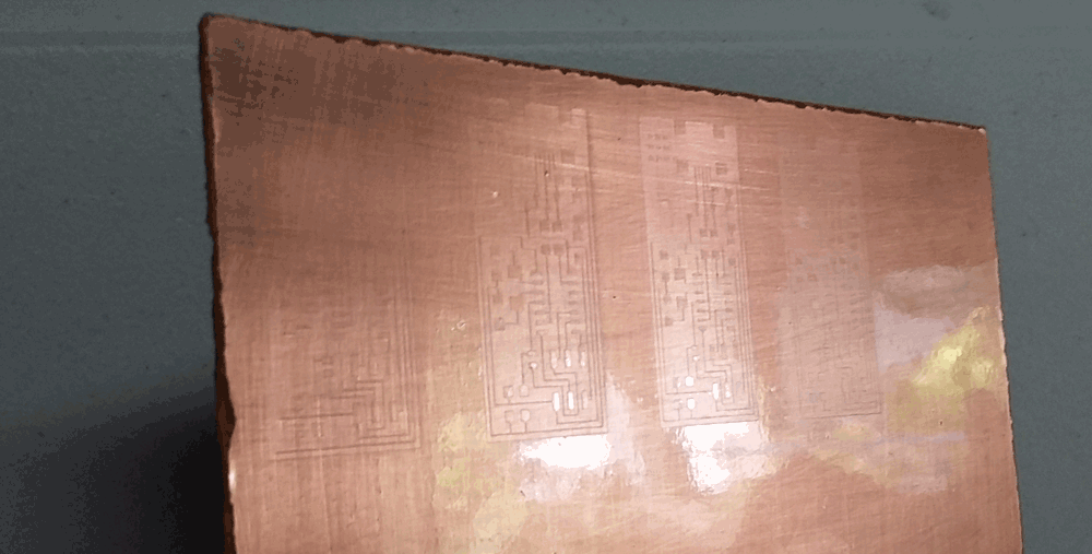
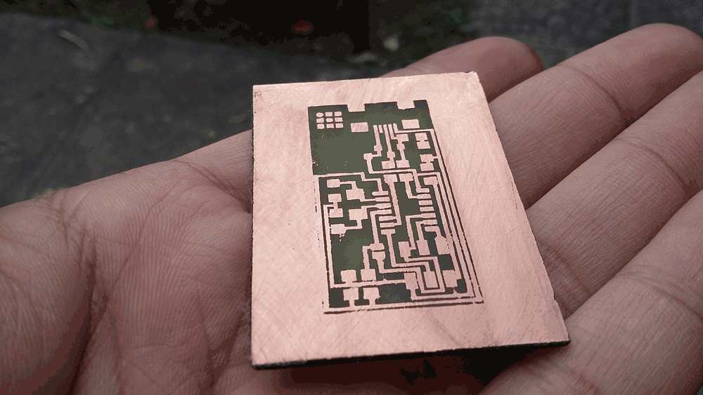
And we need to make this traces

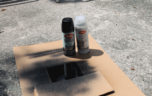
At the beginning we didn’t have all the necessary items, so first we tried with Transparent Acrylic Coating Spray, later we realized that didn’t matter the changes of speed and power we set, there was always a thin coating layer that, we knew, will never let us etching the PCB; so, we had to change the coating spray.
What failed? Well we have a couple of theories:
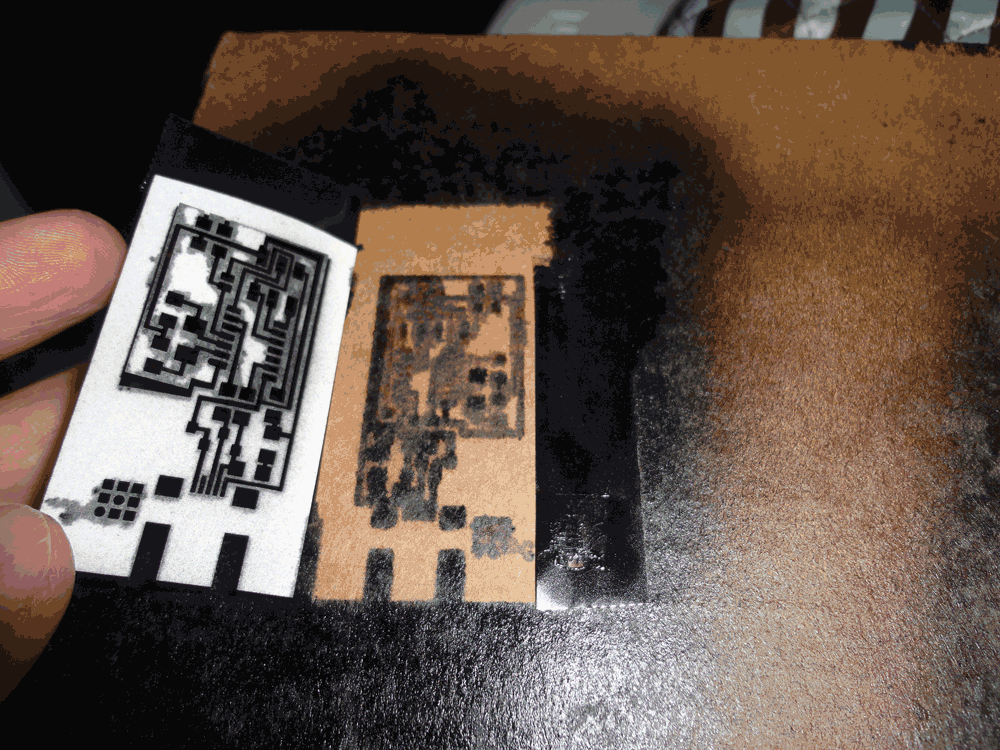
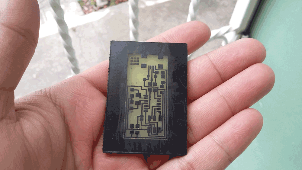
Second try, this time we used a Glossy Black Painting Spray, in this attempt it was easier to see the effect of the laser on the painting, but just like before, in a different way, it looked a thin layer of black paint, this time, more dispersed; so we tried different speeds and power to improve the results. It looked promising and we decided to try the etching process. We prepare the ferric perchloride and submerged one of the recently engrave PCB and voilà, it was HY-DRO-PHO-BIC! This means that repels the water.
But, why did it fail again? In this case we formulate the hypothesis that the laser reach some point too close to the copper, and this caused that the energy dissipates. Maybe the energy it is only enough to degrade the colorant of the paint, but the binder remains, and again, a thin coating layer doesn't let the ferric perchloride etch the PCB.
Recapitulating, during the experiment we had to change some parameters such as:
Cleaning and etching
So we decided to continue and try cleaning the second try’s board, the parts where it’s supposed there is only copper, with isopropyl alcohol, but we had to be very, very, very careful; because otherwise we could erase parts of the circuit, since isopropyl alcohol is used as a solvent and have the capacity to clean all the paint. We also tried with a commercial remover, but it worked almost the same.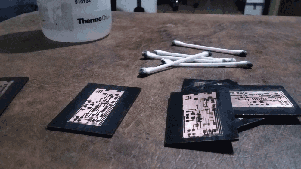
We’ll try with Flat Black Painting Spray too, just to check if the matte spray leaves the same thin coating layer on the board or not, may be is easier to clean and makes the etching process faster.
Hopefully in a near future we’ll have access to make samples and see how a milling machine works!
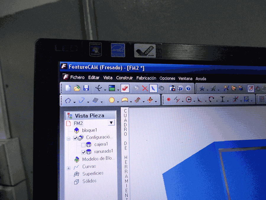
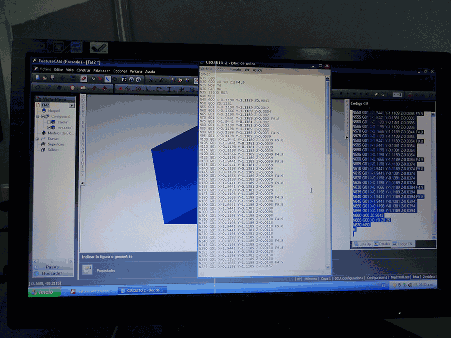
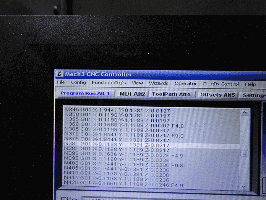
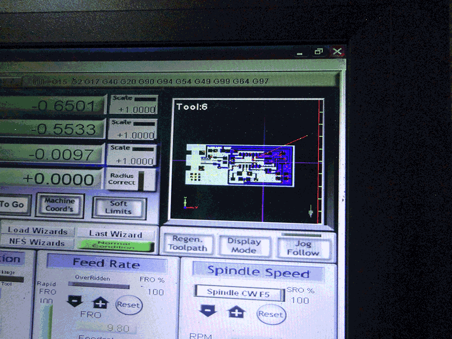
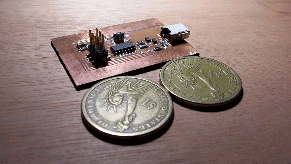
Making the PCB: Part 2
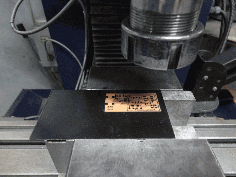
PCB vrs Milling Machine
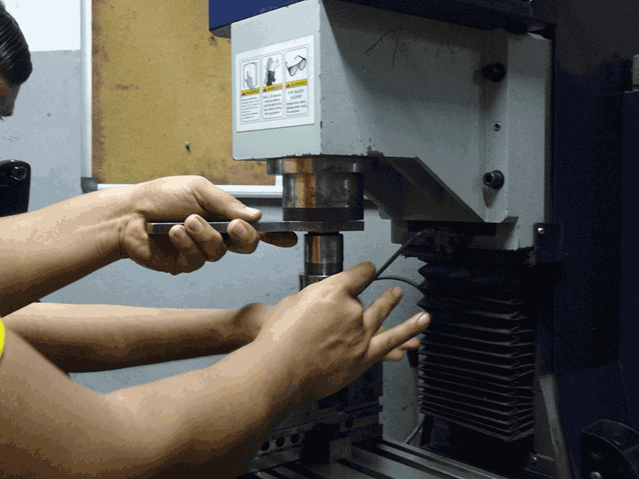
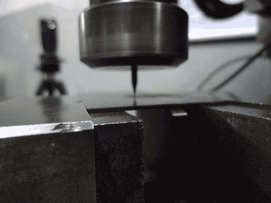
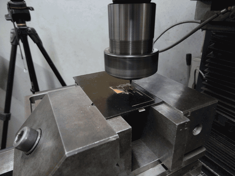
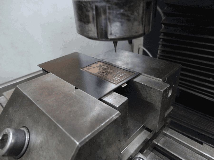
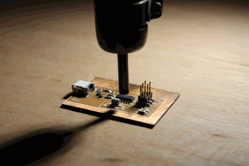
We didn't have a small milling machine dedicated to mill PCBs so we used a big one; but the process is the same.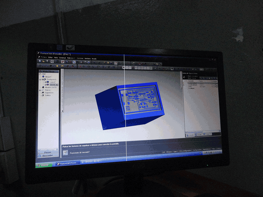
Soldering process
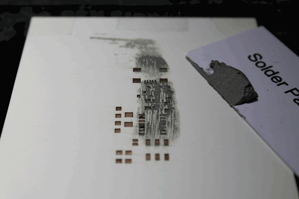
To solder the board first we fixed them to the table, then we use a stencil to apply a solder paste; the stencil only have to have the spots where the pins of the elements are going to be, and we have to apply it with a card with a constant speed and making sure to cover all the holes, we could repeat this process the times we need, inclusive change the stencil if necessary.
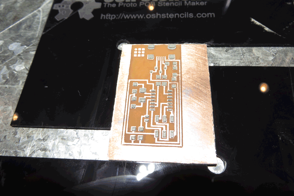
When we finish applying the paste we have to place all the components, this could be the part that take more time, we have to take some consideration such as if the components has polarity, if is sensible to electrostatic, etc… and to manipulate components of this size we definitively need tweezers.
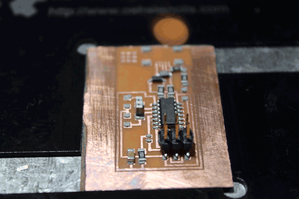
After we have placed all the elements, we used the soldering heat gun, that is a machine that blows heated air and makes the tin melts, this fix the element to the board and allows the electrical conduction between them.
We made a mistake choosing the resonator so we needed to solder it with the iron because it will only work if we solder it on that orientation because only on that way will not touch other traces.
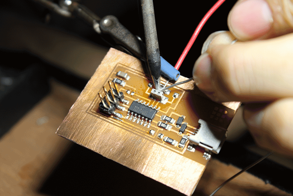
And finally we have to check all the connections, and if everything is alright, it is only needed to clean the board and it’s done.
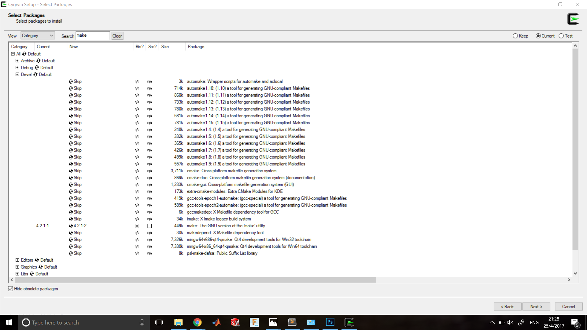
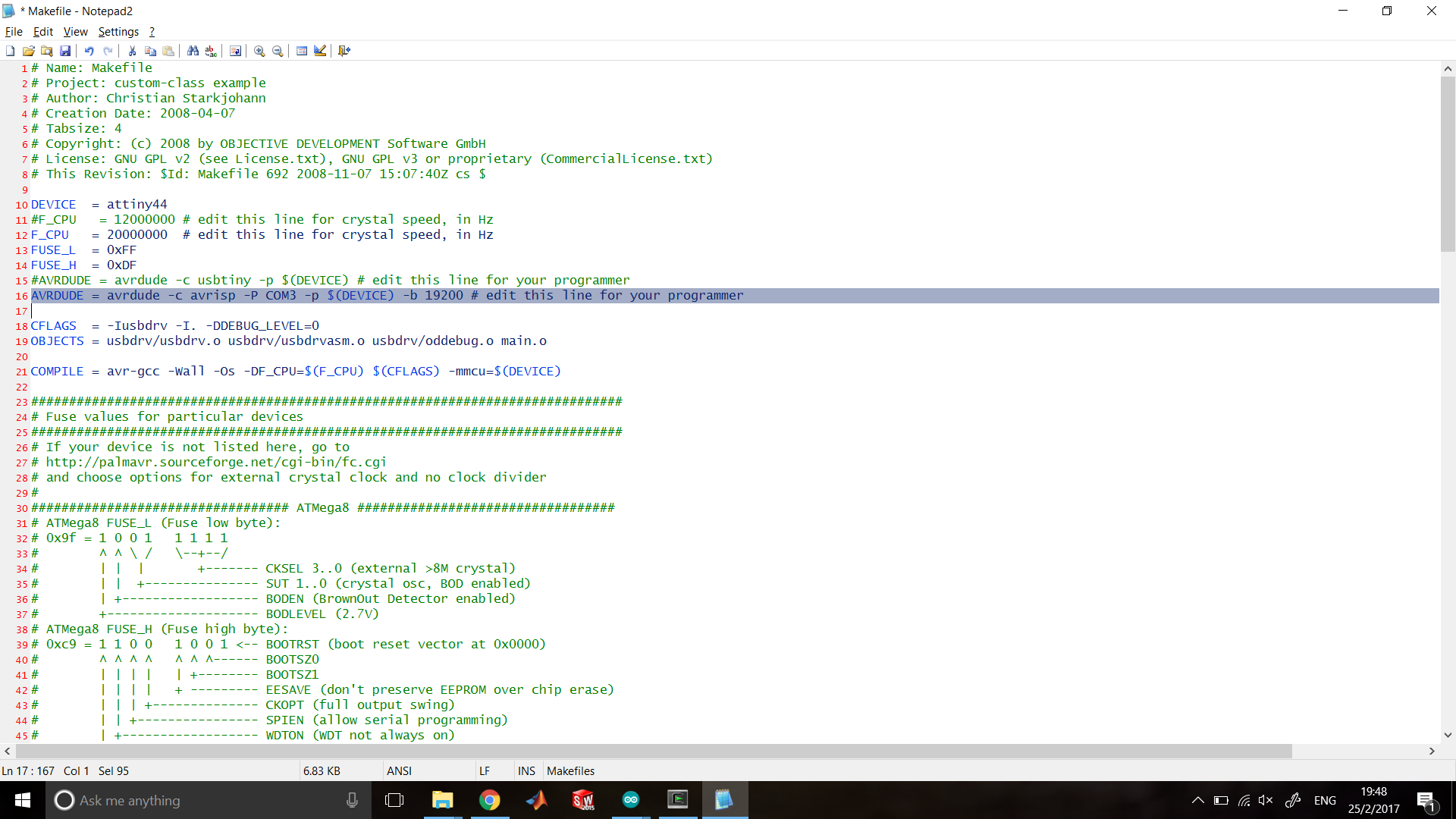
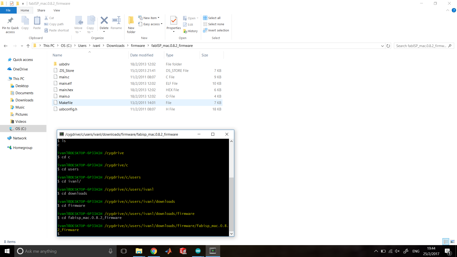
Programing the PCB
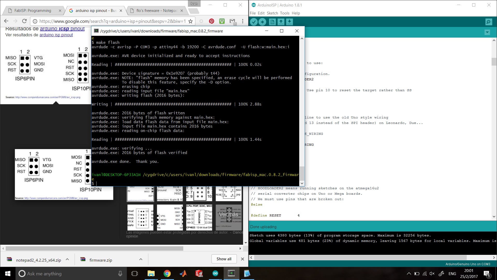
For windows we have to follow this steps:
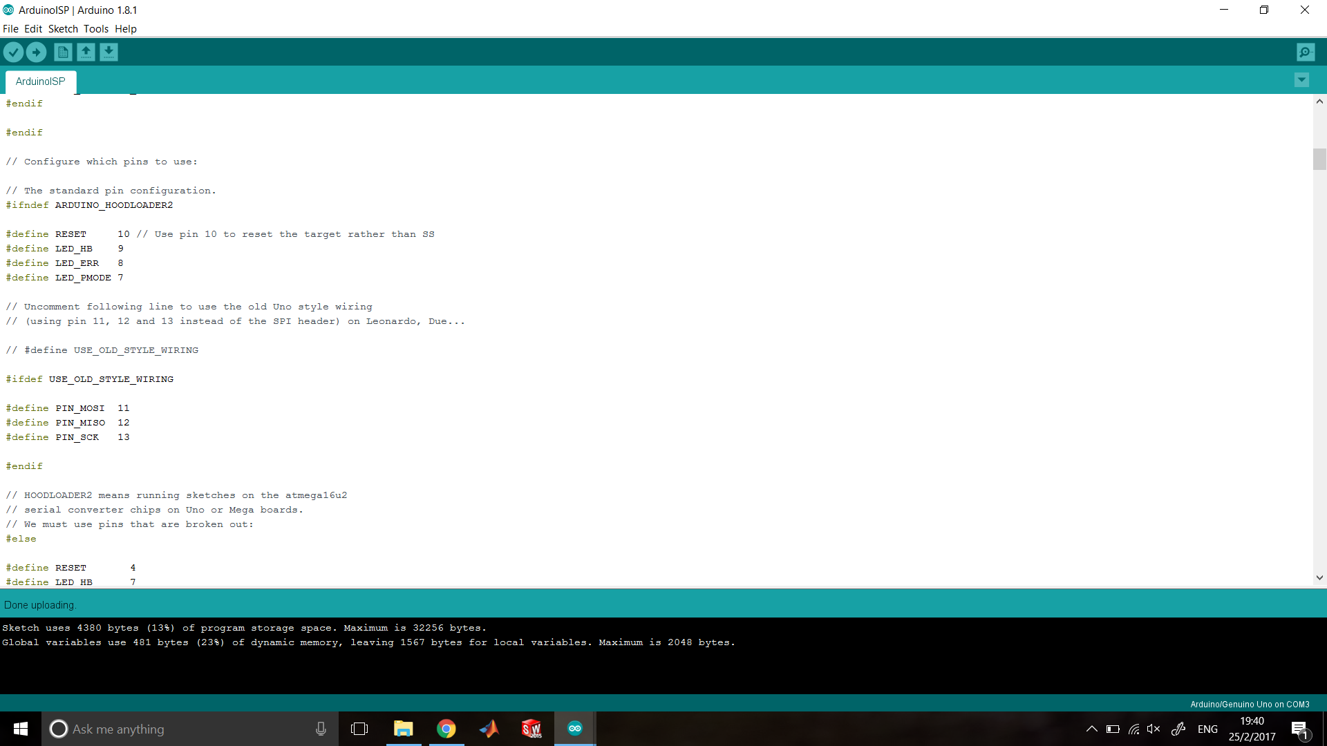
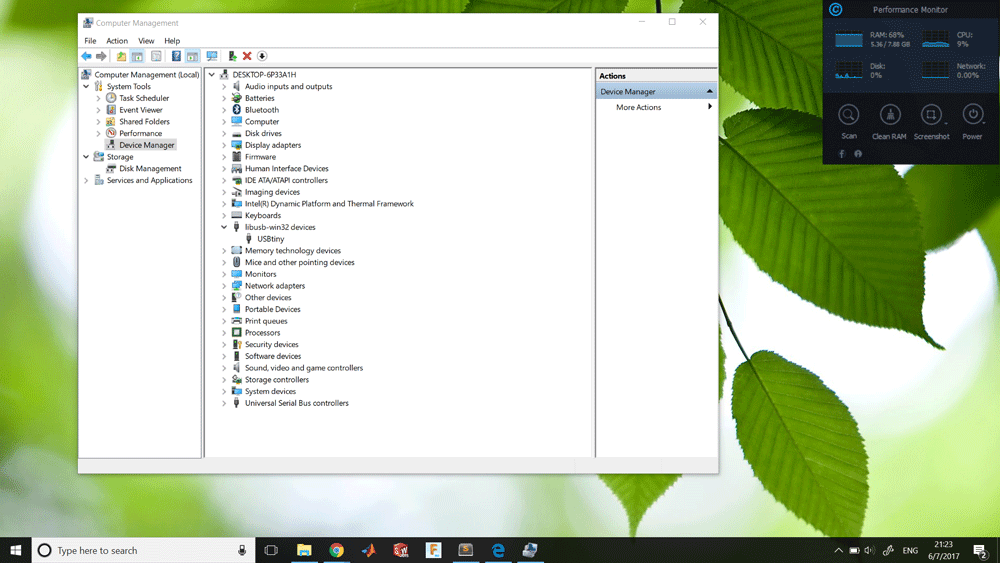
When everything is Ok when you connect FabISP on Windows computer, it will make the sound of a new device, and you could find it on the Device Manager as USBtiny.
I have to say that doesn't work for me at the first time, but I only have to put off the diodes because apparently they doesn't work well at the frequency of the USB communication.
Sponsors