This week we are going to explore reaches and using of 3D Scanning and Printing
Scanning and Printing to Ourselves
To scan us, we used Sense 3D Systems Scanner; this scanner functions by capturing an image with an integrated camera and sensing the distance by a laser.
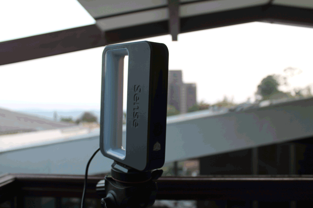
First we setted the scanner on Human>Head, then one by one we sat on a rotary chair in front of the scanner and turned slowly once. That was enough for the scanner to capture all the information to generate a virtual 3D model of us. When we checked that all was alright, we post-processed the information: Solidify the mesh and trim the unnecessary surfaces. Finally we exported into a STL file and now is ready to print.
For printing the previous ourselves scan file, we use a MakerBot Replicator 3D printer. The steps to print are the following:
Bonus: High Precision Scanning
For this scanning we used an Aicon 3D Systems Scanner; this scanner functions by the triangulation of two cameras’s images, of different patterns of light beams projected on the surface of the object.
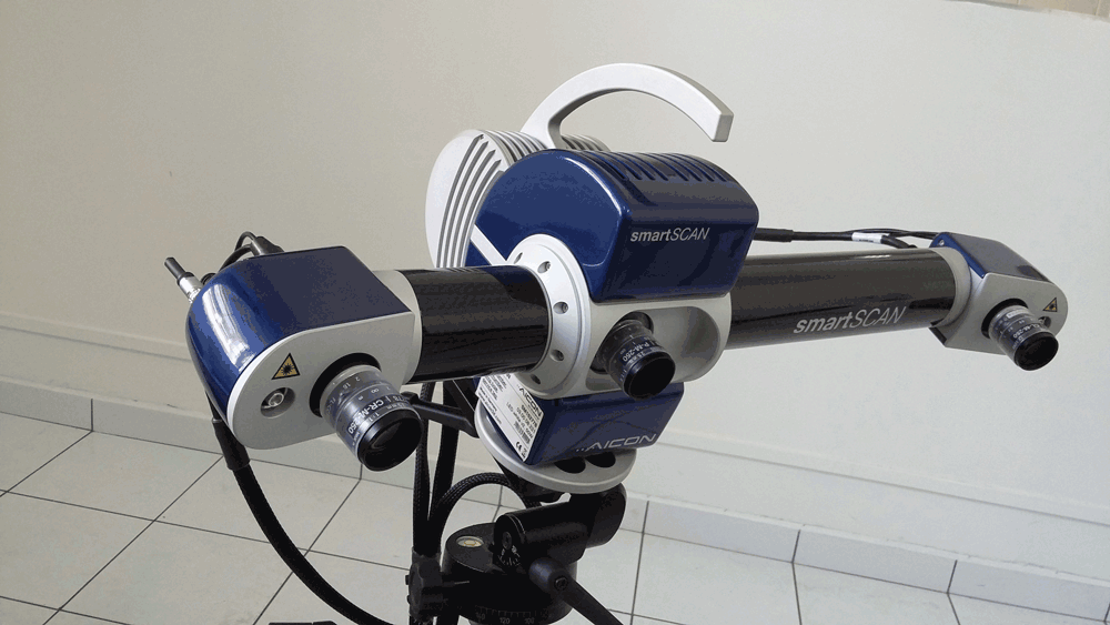
In this case, first we needed to get the room darker, because this scanner has its own light projector to catch only the information of the object we want to scan. When we start the software we have to create a project and decide what kind of scan process we are going to use: Contour scan, that take part of the same object as reference to merge the next scan; or Index points reference, that take circular sticker that we put on the object as reference to merge the next scan. Then we need to calibrate in the software the amount of light that the cameras are capturing, and when this is done we “take a picture”. For the following scans we need to move the object to a new are, respecting the parameters of references that we have chosen earlier, and repeat the last step. If we respect the references the software merge itself the surface. And finally we can export an STL file, but in this case, the solidify process is made in an external software.
Comparision
| Parameter | Sense | Aicon |
|---|---|---|
| Color | Yes | No |
| Resolution | Low | Very high |
| Scanning Time | Very fast | Slow |
| Manipulating Mesh Software | Same | Third party |
| Manipulating Mesh Complexity | Easy | Very complex |
| Computing Resources | Considered | Special |
| Light presence | Helps | Affects |
| Object treatment | - | White flat surfaces |
| Applications | Quick scan, hobby, home projects | Industrial, medicine, inverse engineering |
3D Printing Parameters
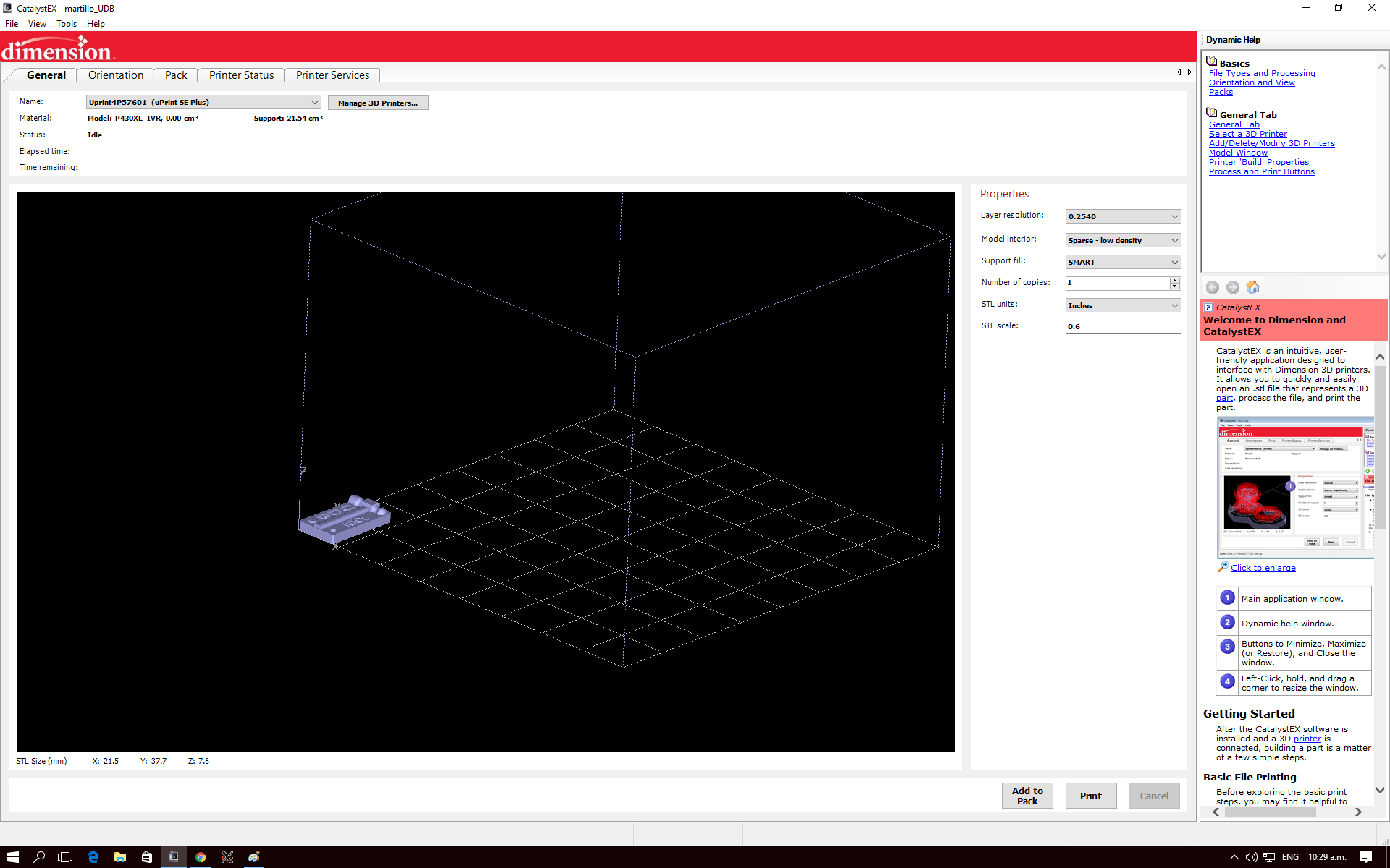
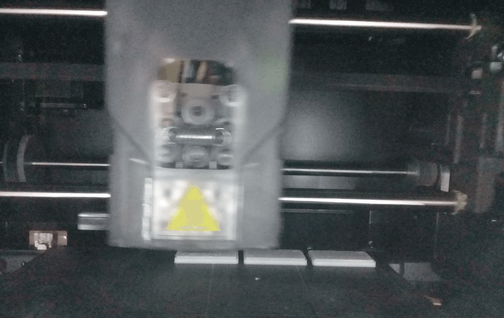
For this part I used a uPrint SE Plus, this 3D Printer let us print with 2 materials, Model and Support, model for the pieces and support to make a base over which the printer deposite the model material, it is also used for the support on complex geometry and temporarily fill free spaces on mobile assemblies.
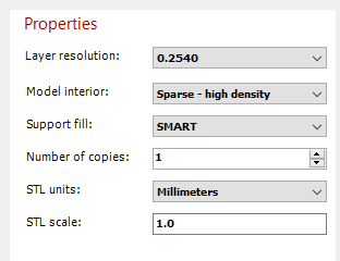
CatalystEX is the slicer and control software for uPrint SE and here we change different settings as:
- Layer Resolution - That determines the thickness for the layer, and therefore, the quantity of layers
- 0.254mm
- 0.3302mm
- Model Interior - Establishes the fill for model material
- Solid - Fill completely the object which means more material, more mechanical resistence and more print time
- Sparse High Density - This is the intermediate parameter of material, time and resistence
- Sparse Low Density - The interior will be filled by a hatch or a honeycomb, reducing the time and material but also de strength
- Support Fill - Determine the quantity and the style for the support material
- Basic - Recommended for basic geometries
- SMART - This is the default choise and has an algorithm that optimize the distribution of the support material for a correct deposition of the modelling material to prevent the deformation of the piece during the print process
- Surround - Support material surround all the piece
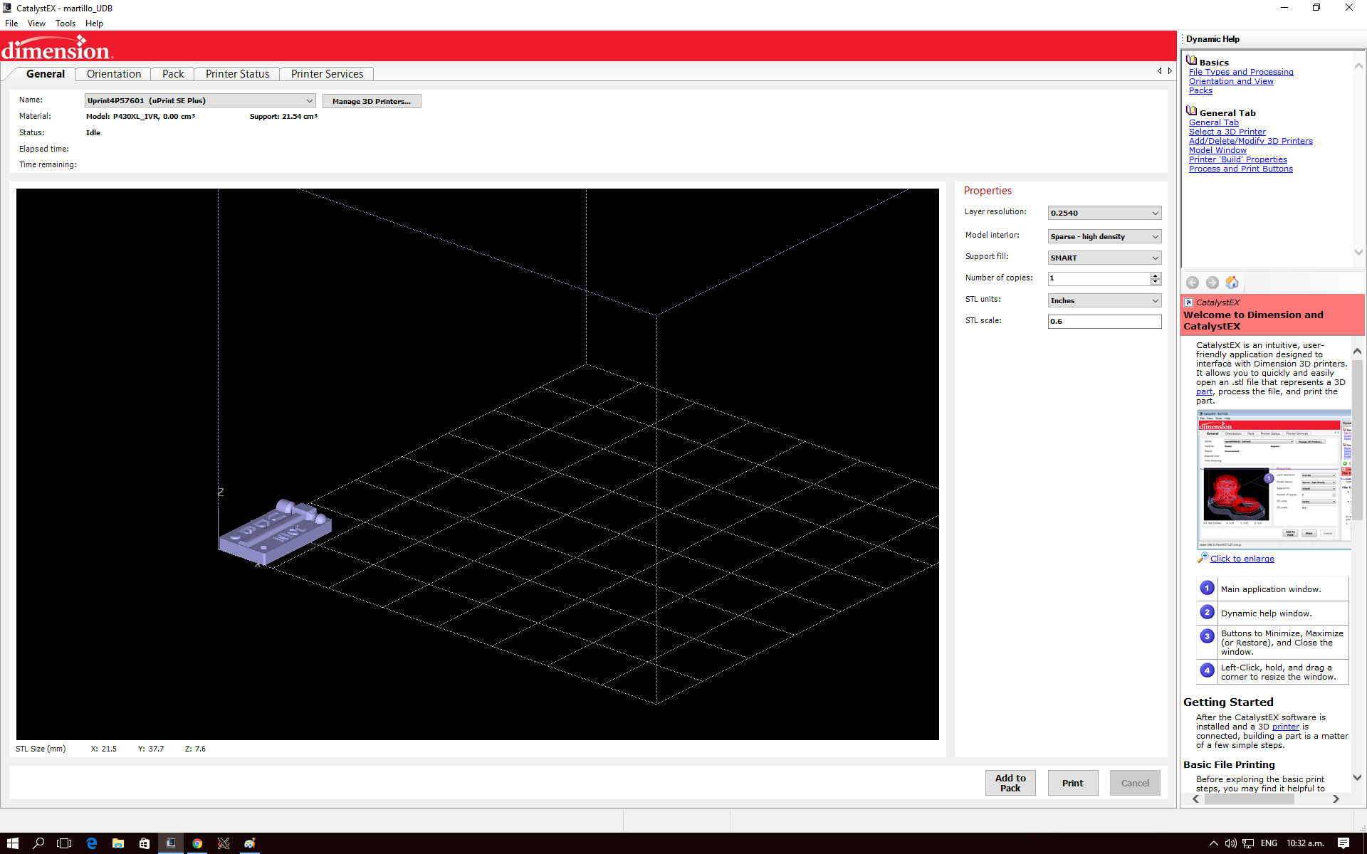
For this comparison I will change the Model Interior parameter for the same object and see how this affect to the material quantity and printing time. I will use this model from a friend of mine.
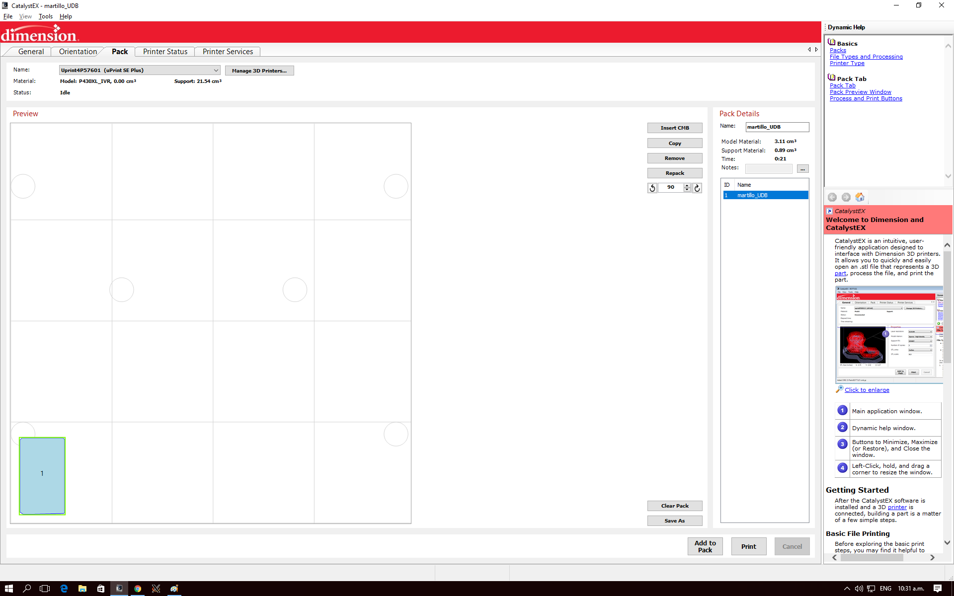
First I'm going to print with the lowest parameters and will be increasing. So I setted low density of modelling material and I get a calculation of the time and material, model and support, this is the information that I will use as reference.
- Model Material: 3.11cm3
- Support Material: 0.89cm3
- Time: 21min
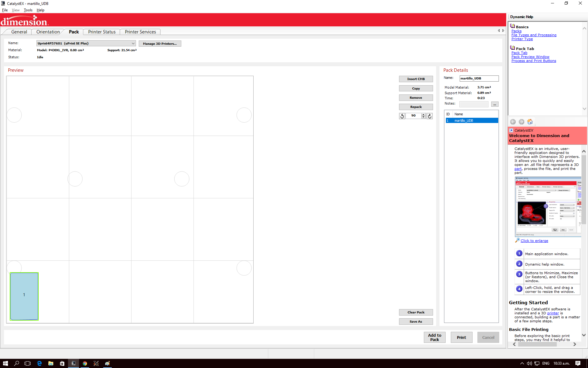
For the second try I setted the model interior on high density
- Model Material: 3.71cm3
- Support Material: 0.89cm3
- Time: 23min
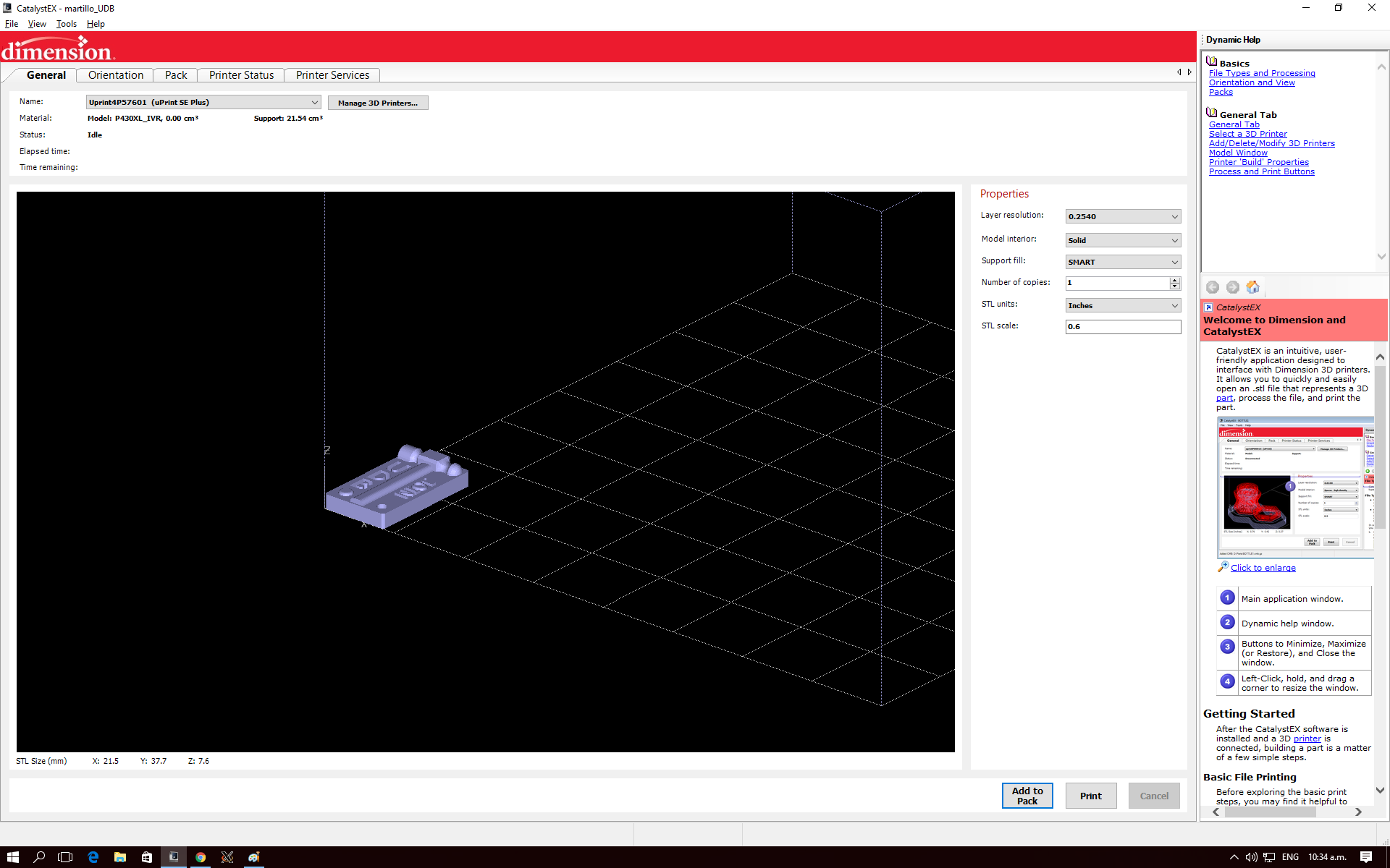
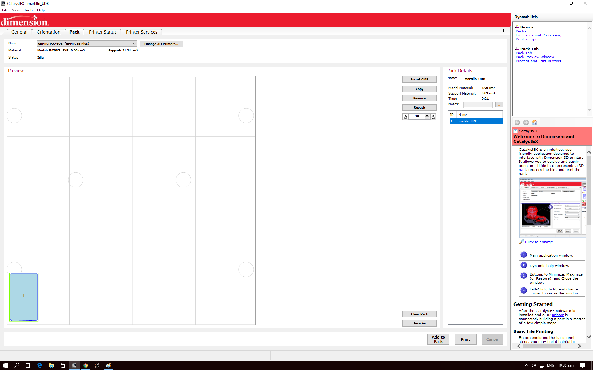
And finally I will set the infill as solid
- Model Material: 4.08cm3
- Support Material: 0.89cm3
- Time: 21min
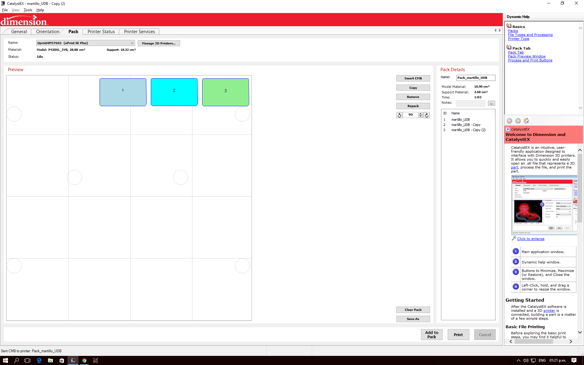
After making the individual virtual comparision I printed the three models
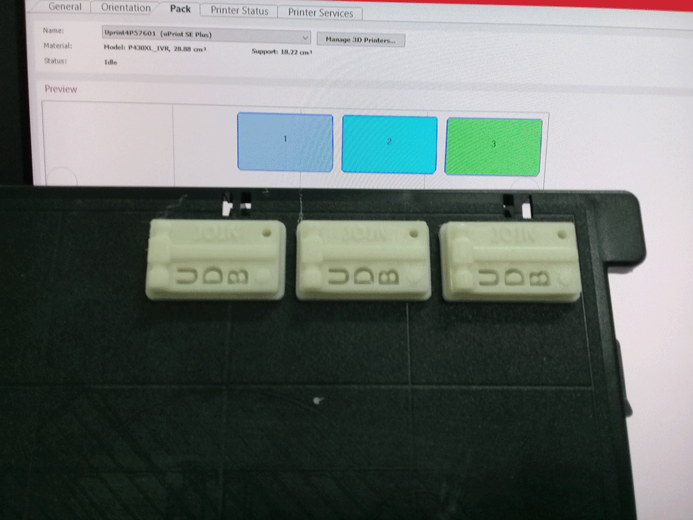
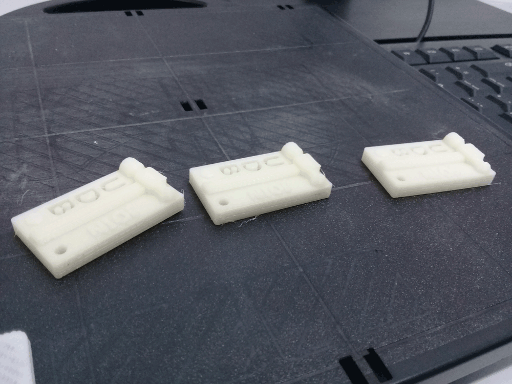
Having printed the objects I could see that the difference are minimal, besides a slight difference in weight and mechanical resistence to flexion, at this scale the differences are practically imperceptible.
3D Printing Projects
For Mechanical Design Project I designed/modified and printed a couple of parts:
Motor coupling
To make the union between the motor and the rod I had to modify this motor coupling that we found on thingiverse and then printed it with PLA.To modify the STL file we used Autodesk Fusion 360:
End effector support
During the project we decided that the end effector it was going to be a marker, so I designed a marker holder, where the marker fits by pressure. And the only three parameters that we need to consider are the marker diameter, diameter and height of bolts.3D Printing Comparision
| Parameter | MakerBot | uPrint SE Plus |
|---|---|---|
| Color | Yes | Yes |
| Resolution | Good | Very high |
| Support Material | Same model material | Soluble support material |
| Enclousure | Open | Close |
| Manipulating Print Parameters | Highly manipulable | A few predefined parameters |
| Cost | Medium | High |
| Finish details | Acceptable | High Quality |
| Post Process | Cut supports | Submerge in solvent to remove the support material |
Sponsors