This week we are going to build a mechanism to as a first step to make a machine, we are going to use James Coleman and Nadya Peek project as a tutorial to construct our 2 axis CNC drawing machine.
Machines
Laser Cutter
3D Printer
Materials
Cardboard sheets 30”x40”
Wooden round molding sticks 7/16” x 48”
Threaded rod 3/8”
Step motors Wantai 42BYGHM809
Nuts and bolts
Acrylic sheets 3mm
Silicone liquid glue
Adhesive velcro tape
MTM 2: ‘Maggie’ CNC Drawing Machine
This is a groupal activity, so we devided all the activities, I will document what I've done but you can find the whole project here
[Re]Design Process
Motor coupling
To make the union between the motor and the rod, we use a PLA 3D printing coupling, we fix the rod and the coupling piece with super strength glue, and to the motor pin by pressure.We had to modify this file that we found on thingiverse, because the hole to put the motor pin was to small. First we tried printing the coupling with PLA and drilling the hole, but we realized that PLA sticks on the drill when it gets hot by the friction (so we messed up a drill). Then we tried a better solution, we modified the STL file to print it later.
To modify the STL file we used Autodesk Fusion 360:
View larger
View larger
End effector support
As we have already decided that the machine will draw with a marker we have to make the piece that will support the marker. We used SolidWorks to design it, and the only three parameters that we need to consider are the marker diameter the bolt diameter and height. We have some inconvenients to printing it, because we didn’t consider the tolerances of the 3D printer and when we tried to put the bolts and the marker, they didn’t fit, so we had to increase a little this dimensions, like decimal of millimeter.View larger
View larger
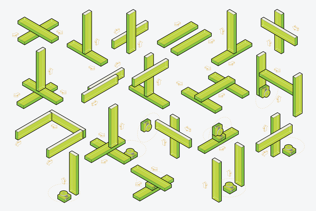
Frame Assembly
We followed step by step the tutorial and we finally had the two large boxes assembled, at this moment we used the pieces we redesign.The challenge was how to join the two boxes to make the X and Y axis, to do that we use the support frame to have the two axis at the right distance to the table to put the marker in its place.
View larger
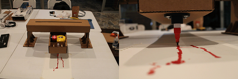
Process and Results
Sponsors