This week we are going to learn how to use a laser cutter and explore the parameters we can use with each material
Machines
Laser Cutter
Materials
Cardboard
MDF
Acrylic
Testing
Kerf
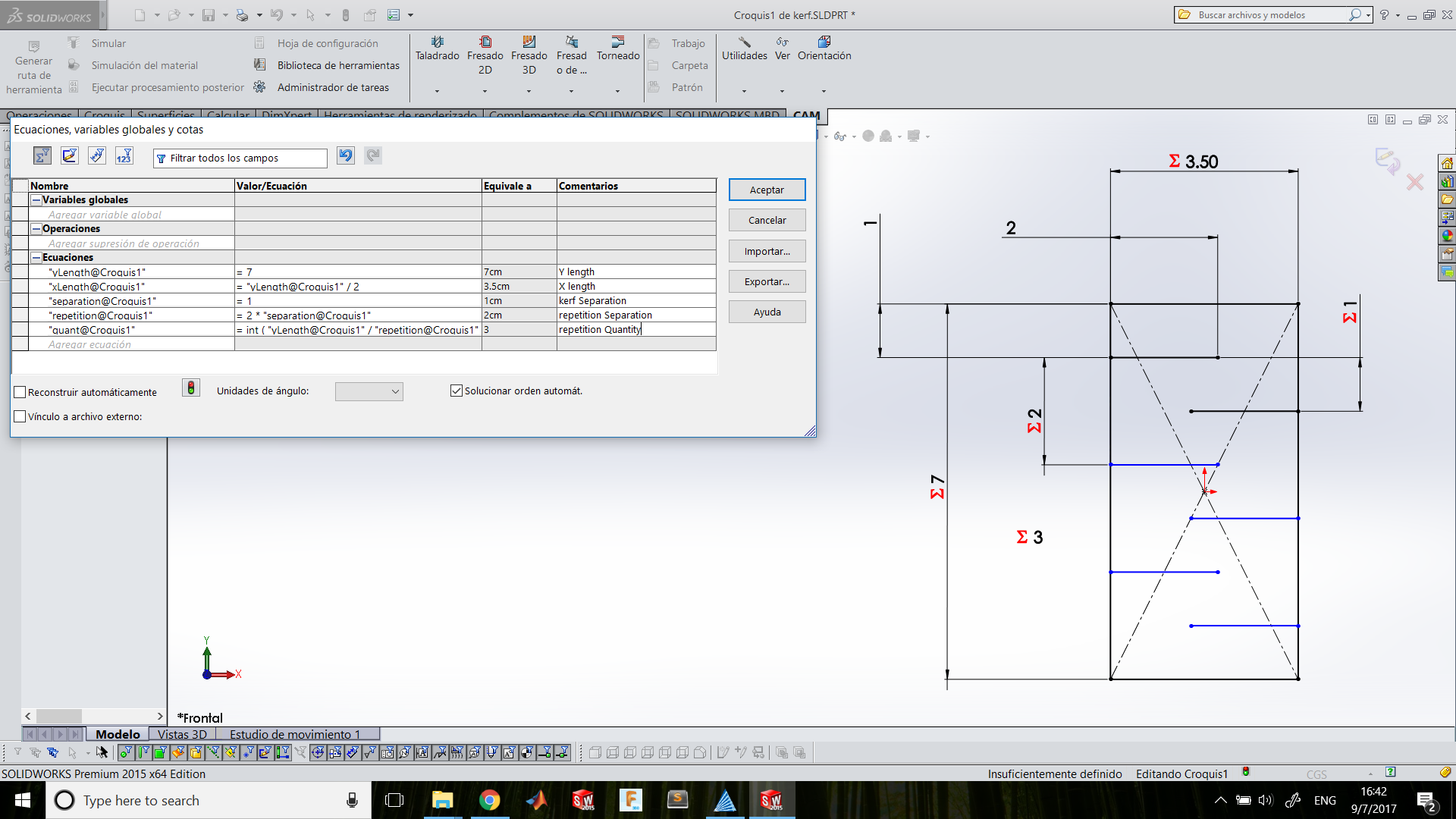
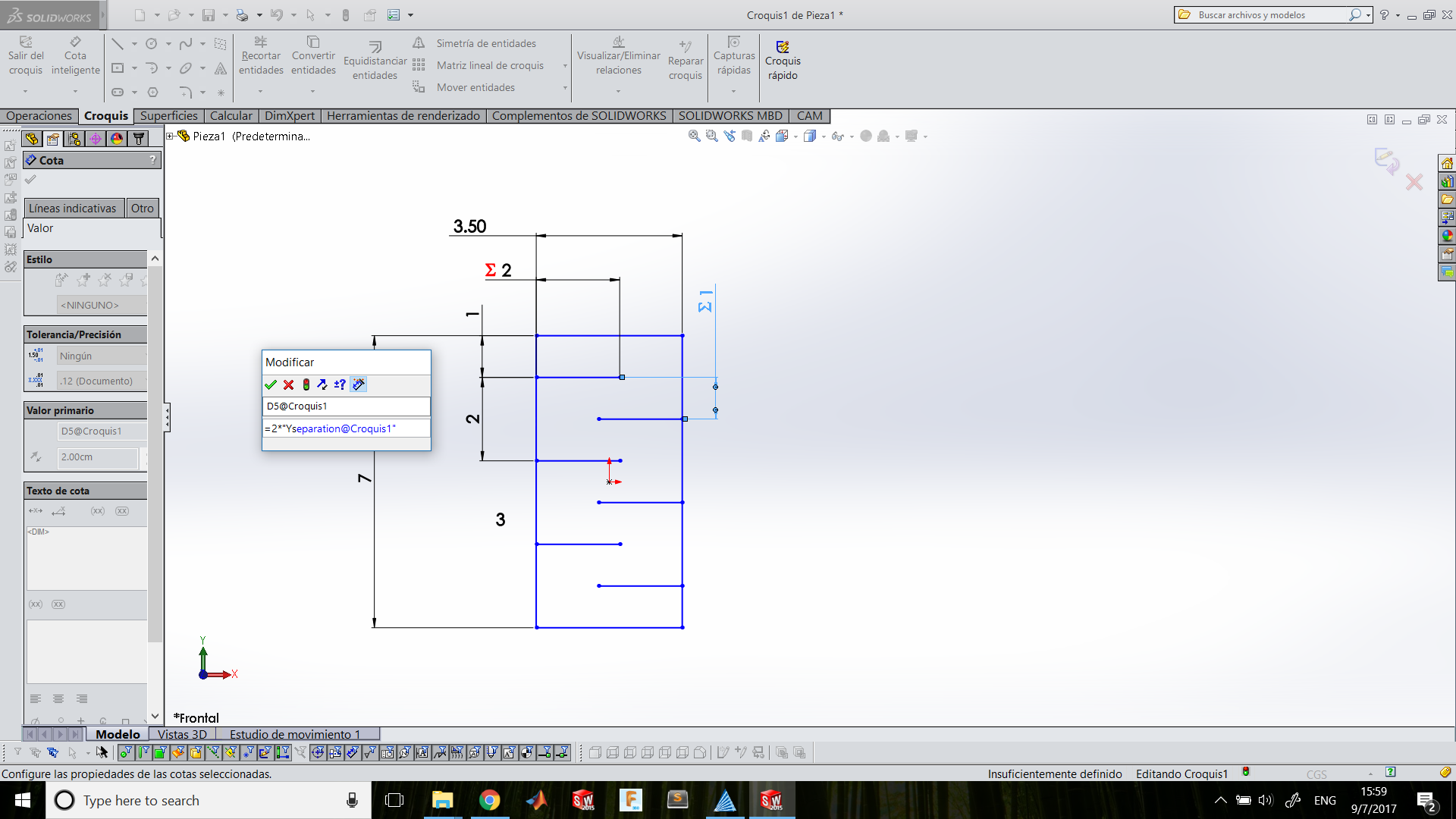
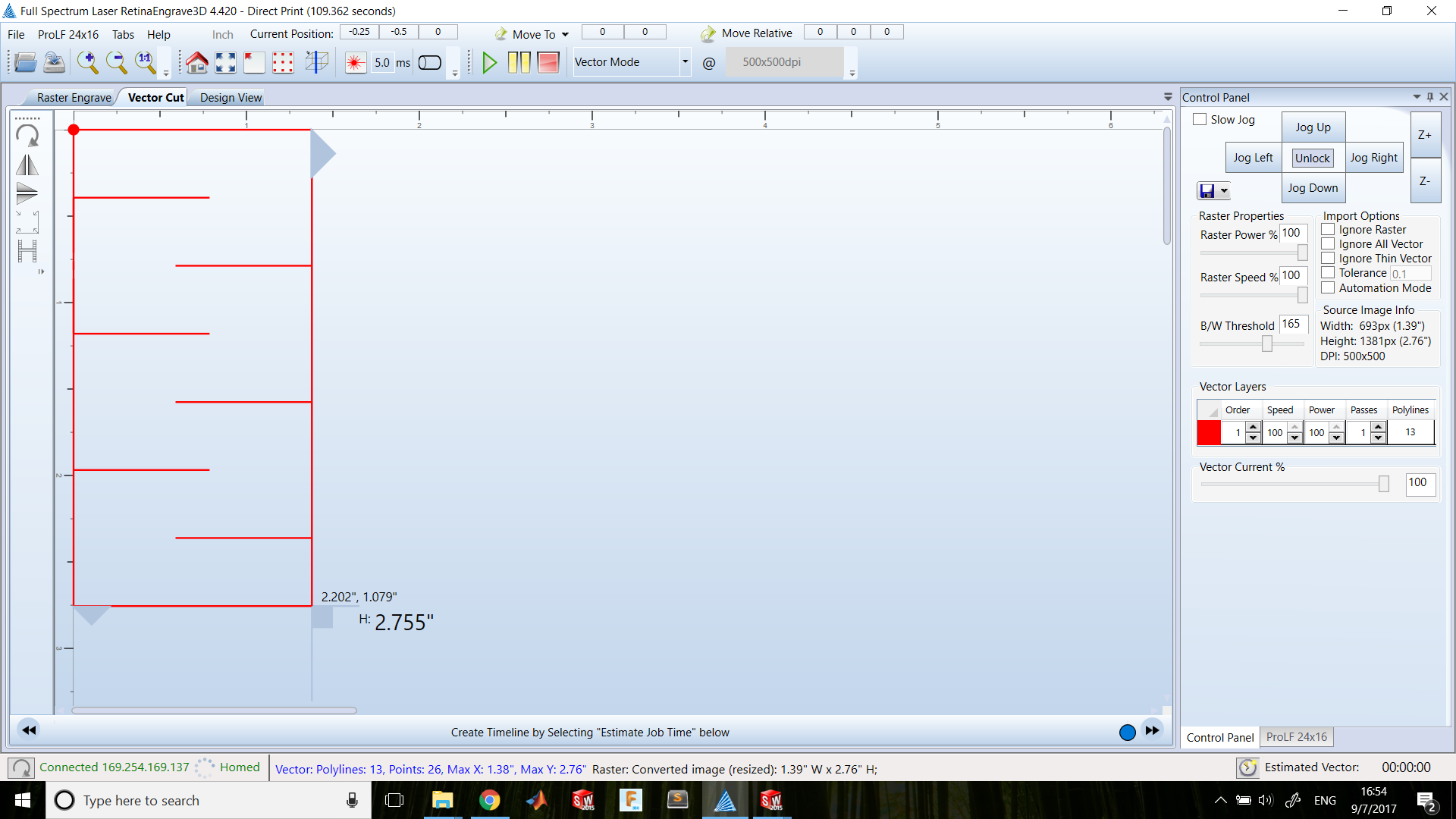
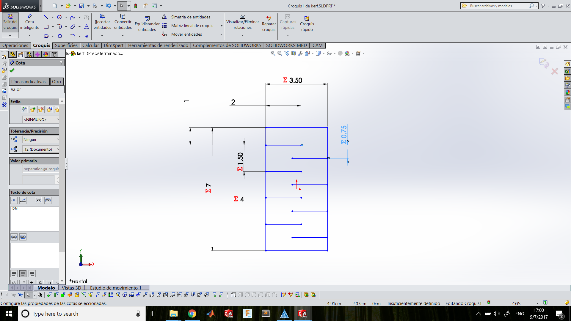
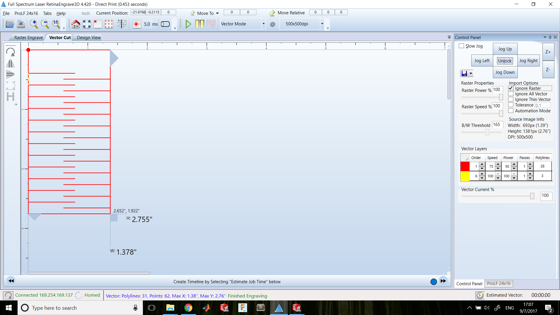
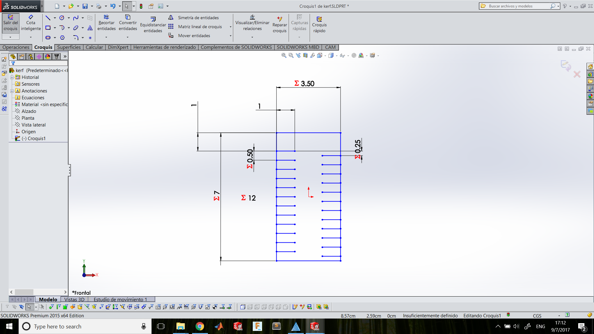
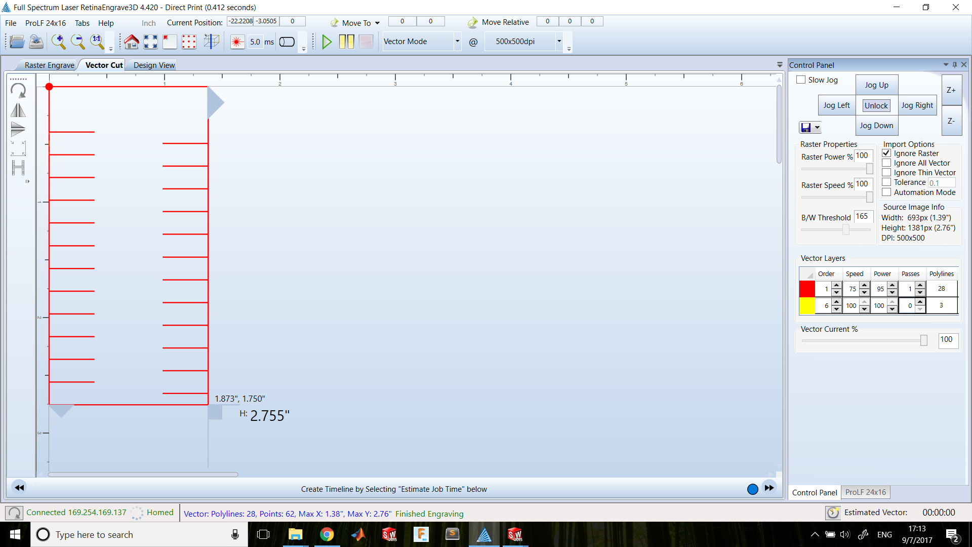
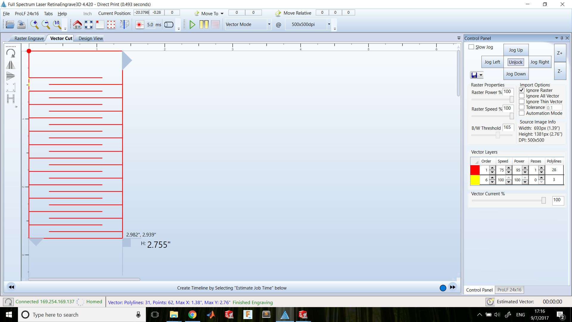
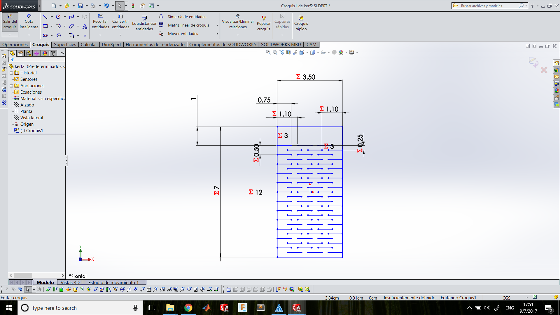
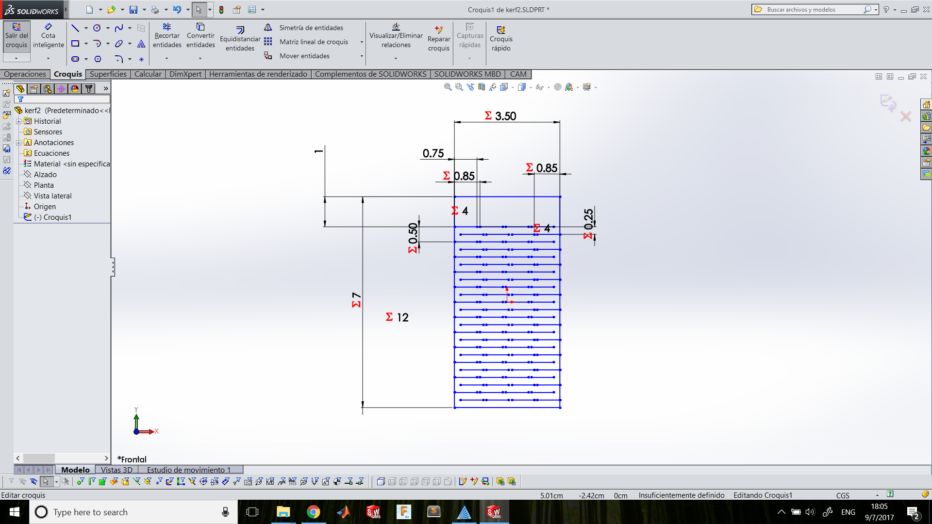
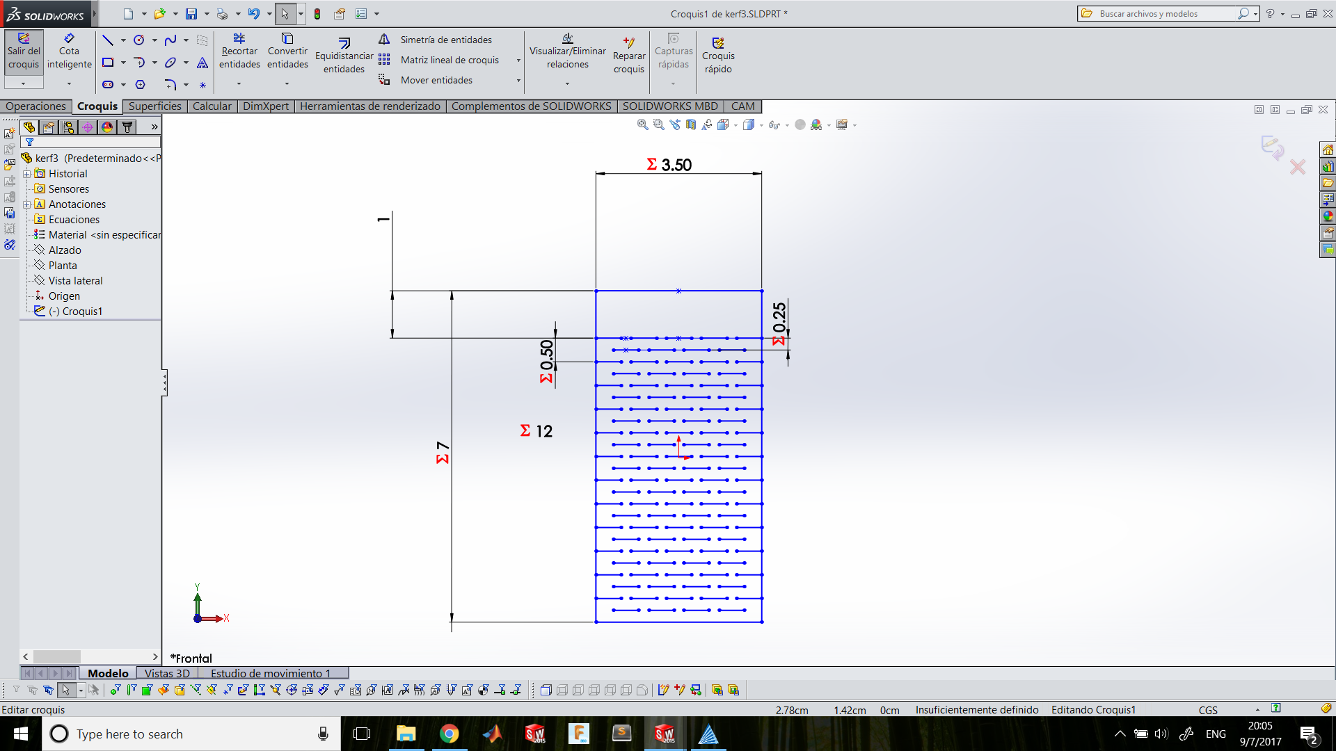
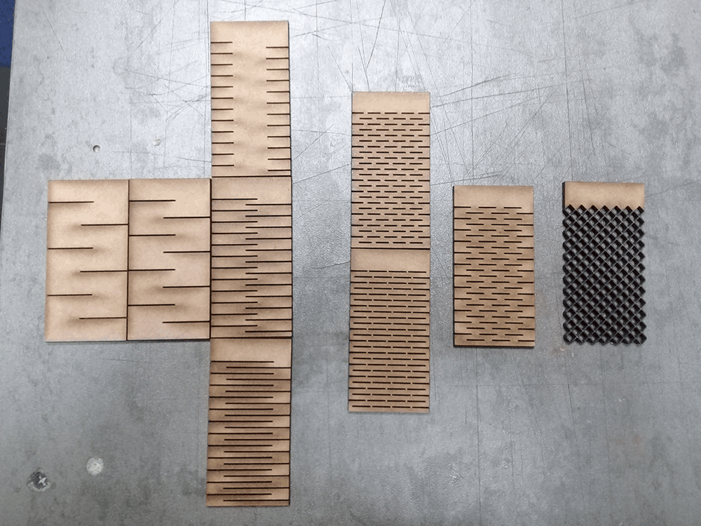
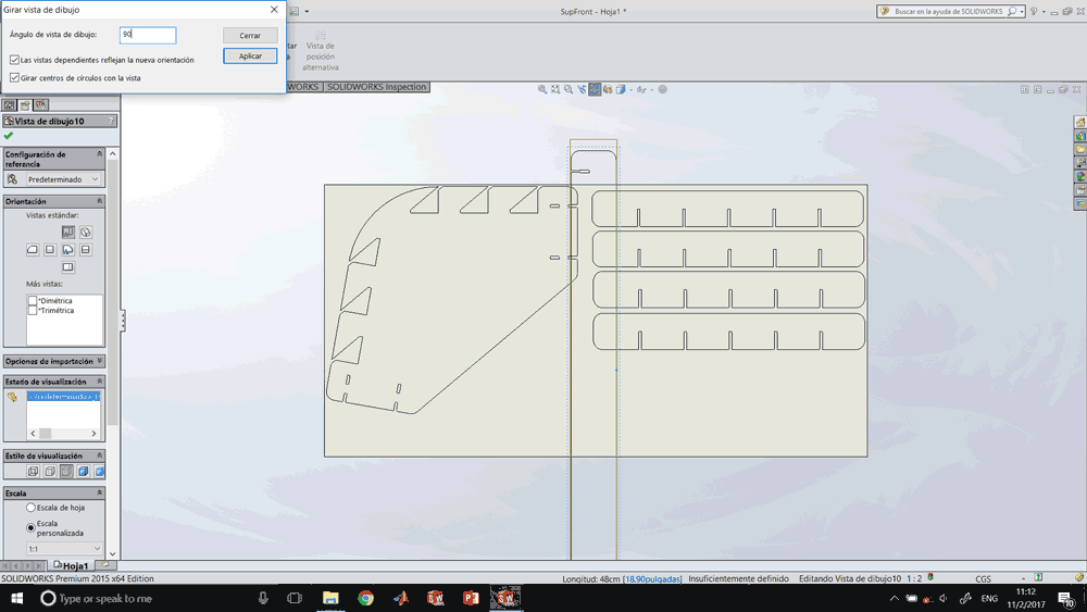
I used SolidWorks to make parametric kerf testing. First I make a base sketch with which I was going to work. I defined some parameters on its dimensions which I could modify from Equations Manager.The parameters that I defined was X and Y dimensions that are constant, kerfs length and separation that are the parameters that I will modify, and quantity that fits on the testing coupon that will be automatically calculated.
-
Kerfs length: 2cm
Separation: 1cm
Strips: 1
-
Kerfs length: 2cm
Separation: 0.75cm
Strips: 1
-
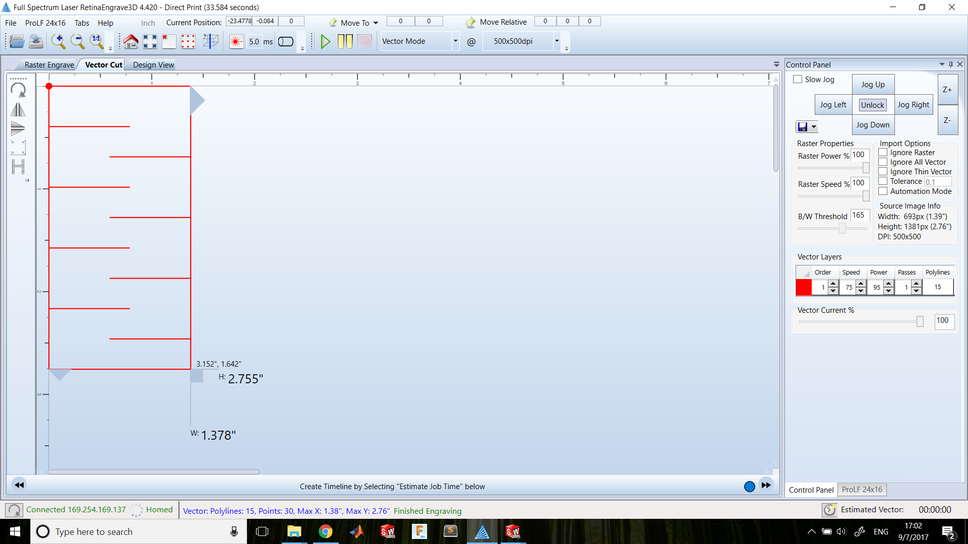
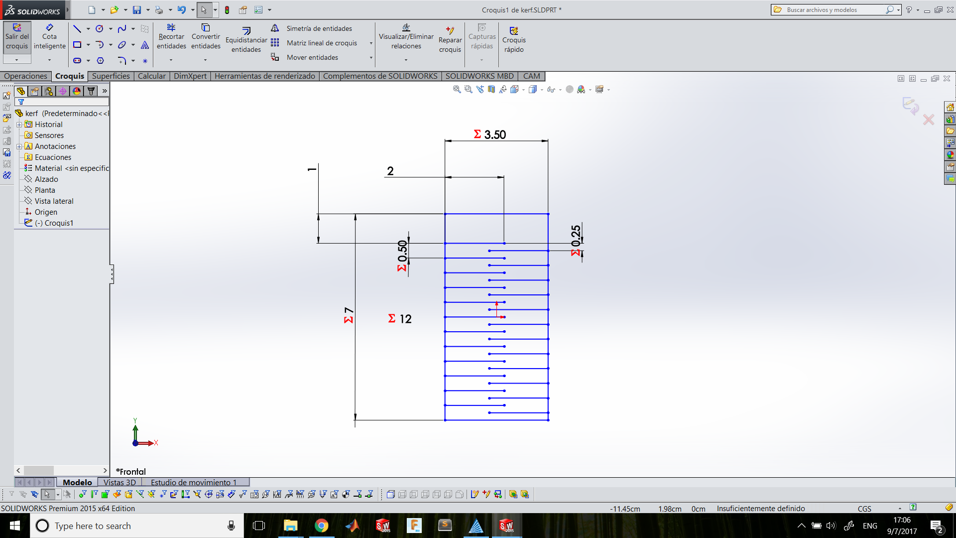
Kerfs length: 2cm
Separation: 0.25cm
Strips: 1
-
Kerfs length: 1cm
Separation: 0.25cm
Strips: 1
-
Kerfs length: 2.75cm
Separation: 0.25cm
Strips: 1

-
Kerfs length: 0.75cm
Separation Y: 0.25cm
Separation X: 0.35cm
Strips: 3
-
Kerfs length: 0.75cm
Separation Y: 0.25cm
Separation X: 0.10cm
Strips: 4
-
Separation Y: 0.25cm
Strips: 5 equidistant
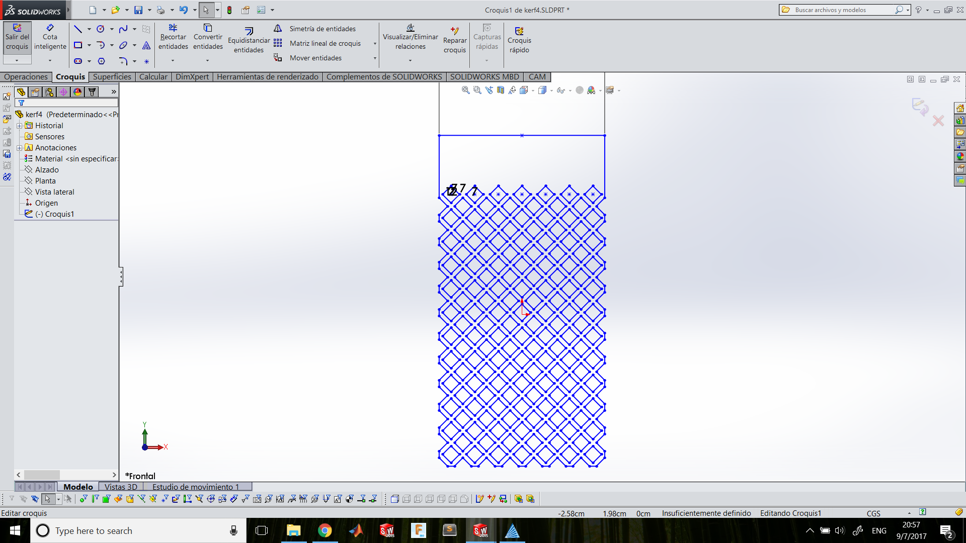
-
Shape: Rhombus
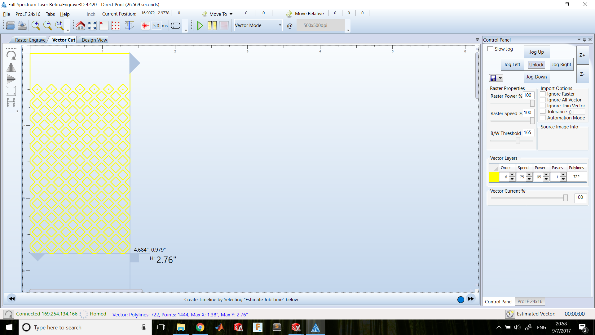
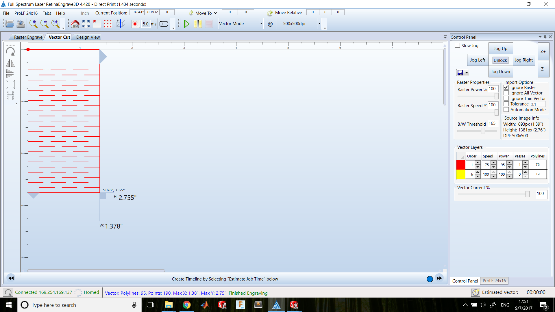
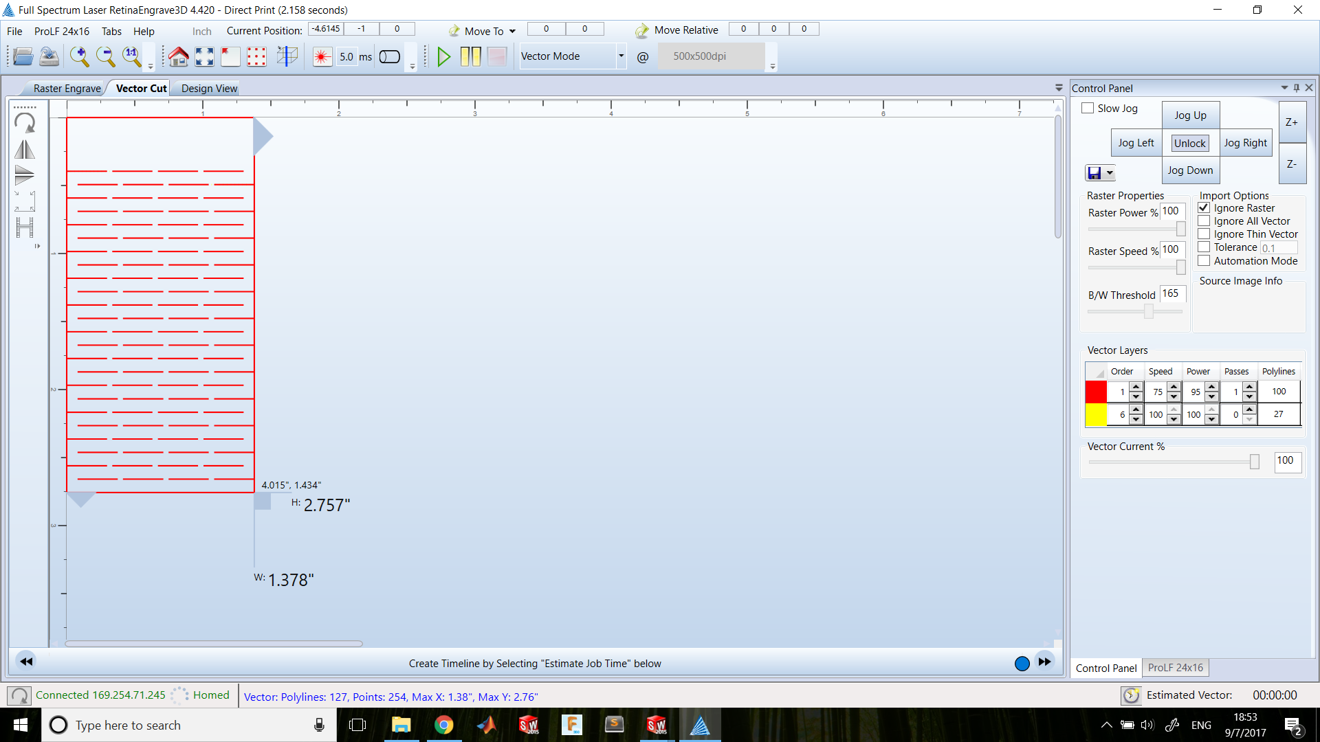
I cutted 3mm MDF with 75% of Speed and 95% of Power and try to bend every coupon to see it rigidity.
Week 3 - Kerf Testing from Ivan López on Vimeo.
Press fit
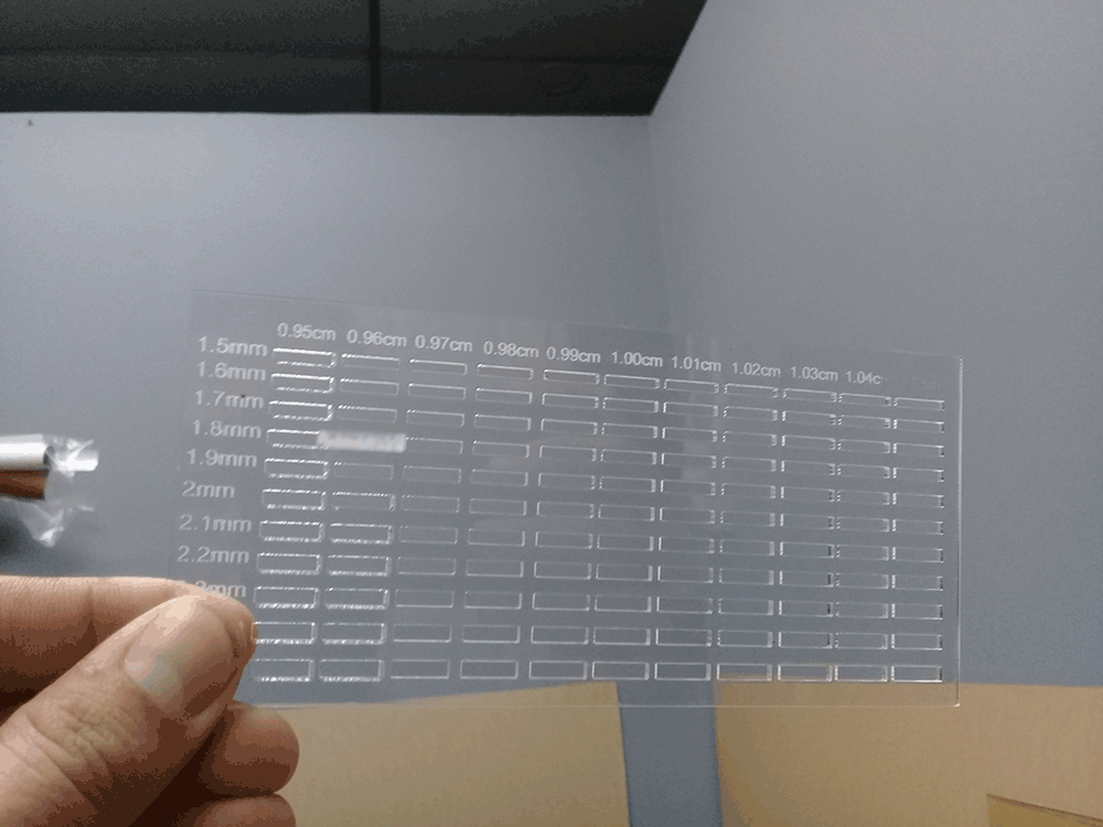
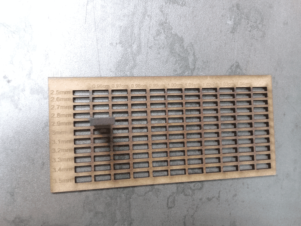
I also made a press fit test board for two different materials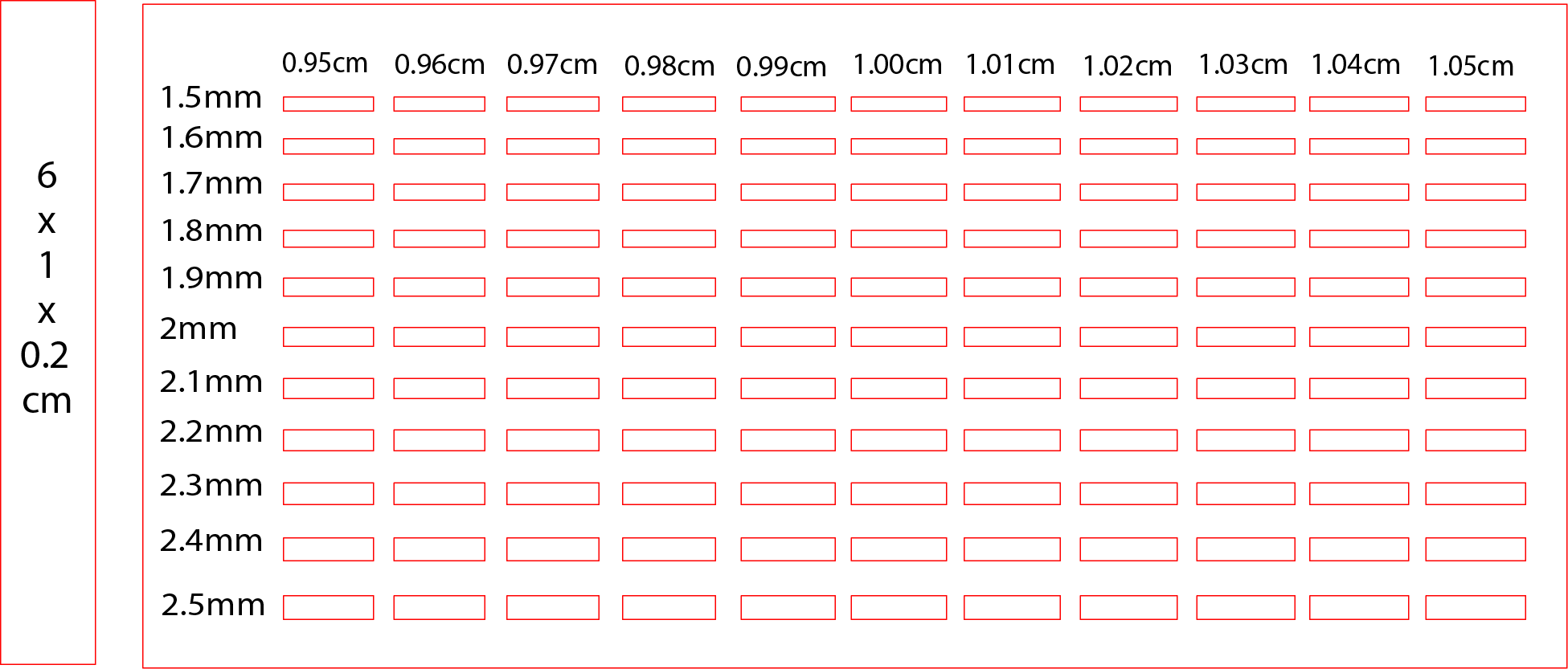
I cutted 2mm Acrylic with 80% of Speed and 100% of Power, and rastered text with 20% of Power and 100% of Speed.
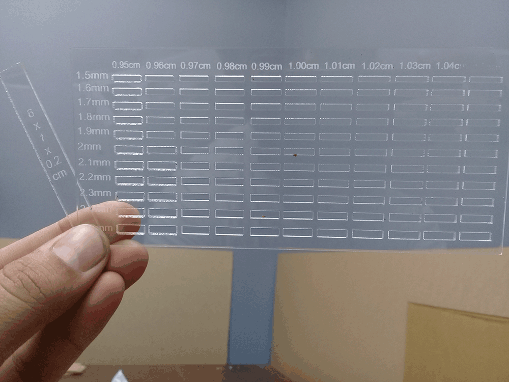
And try which hole fits better with the 6x1x0.2cm stick, and I realized that we actually have to make holes smaller than male joint, because the hole that fits were 0.96x0.18cm, a couple of millimeter less.
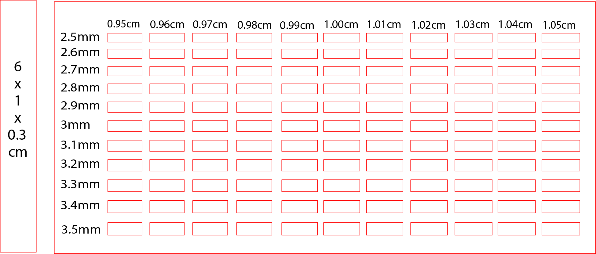
I cutted 3mm Acrylic with 75% of Speed and 95% of Power, and rastered text with 20% of Power and 100% of Speed.
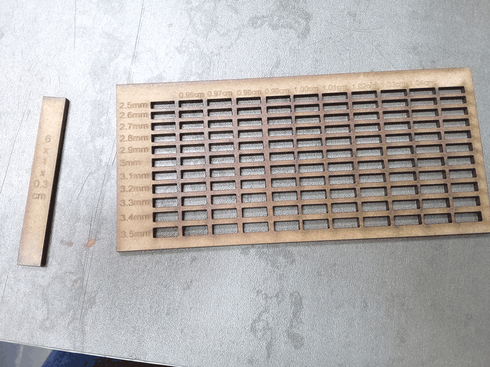
And try which hole fits better with the 6x1x0.3cm stick, and I realized that we actually have to make holes smaller than male joint, because the hole that fits were 0.96x0.29cm, a couple of millimeter less.
Press-fit Construction Kit
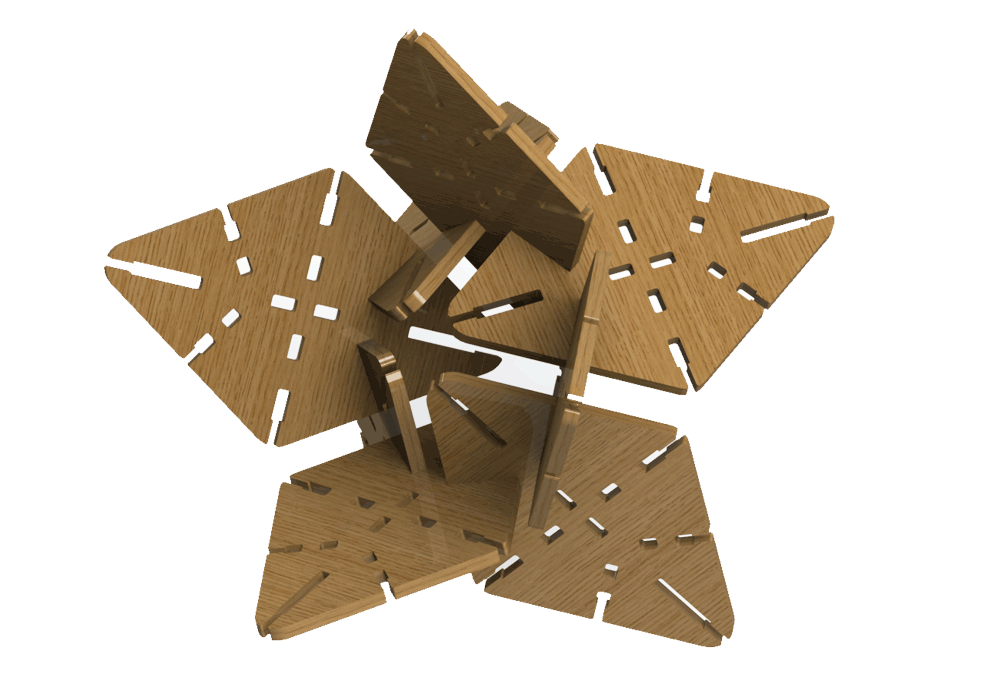
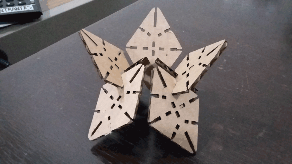
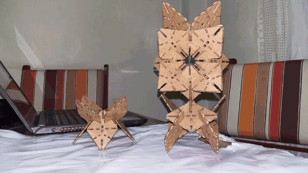
Concept
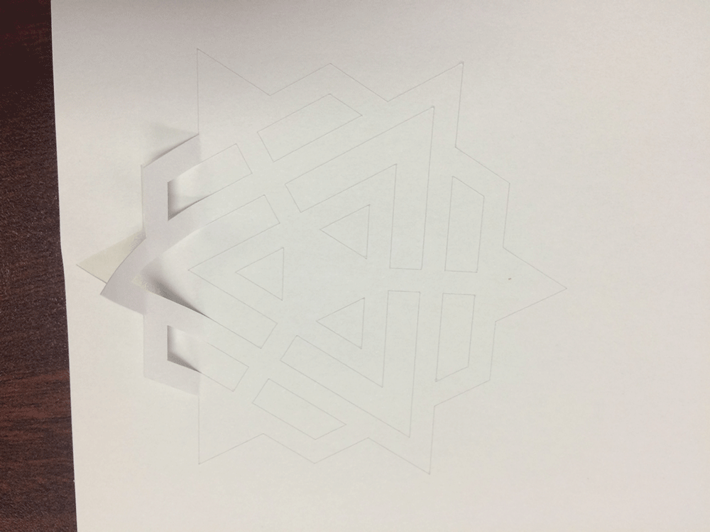
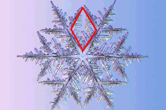
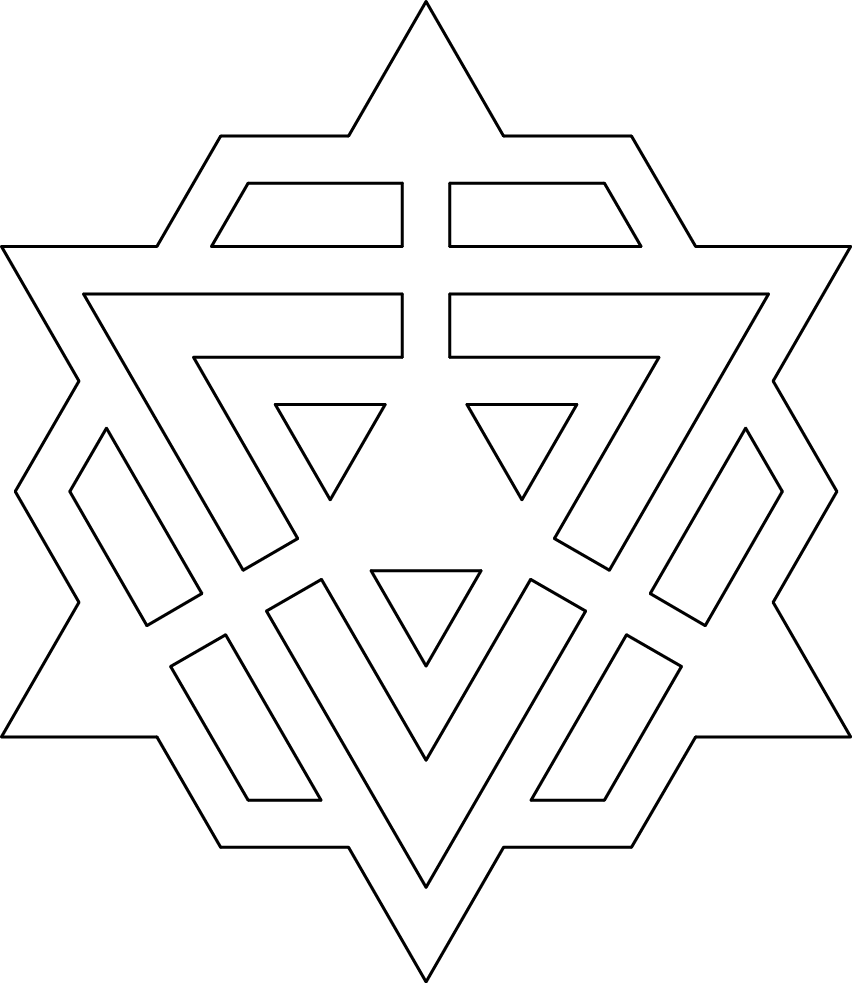
My idea was to create a press-fit module inspired in the form of a snowflake. So in my serch for inspiration I found this image and I realized that I could use this geometry as a base to reach something like a snowflake.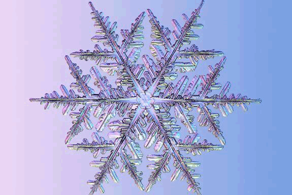
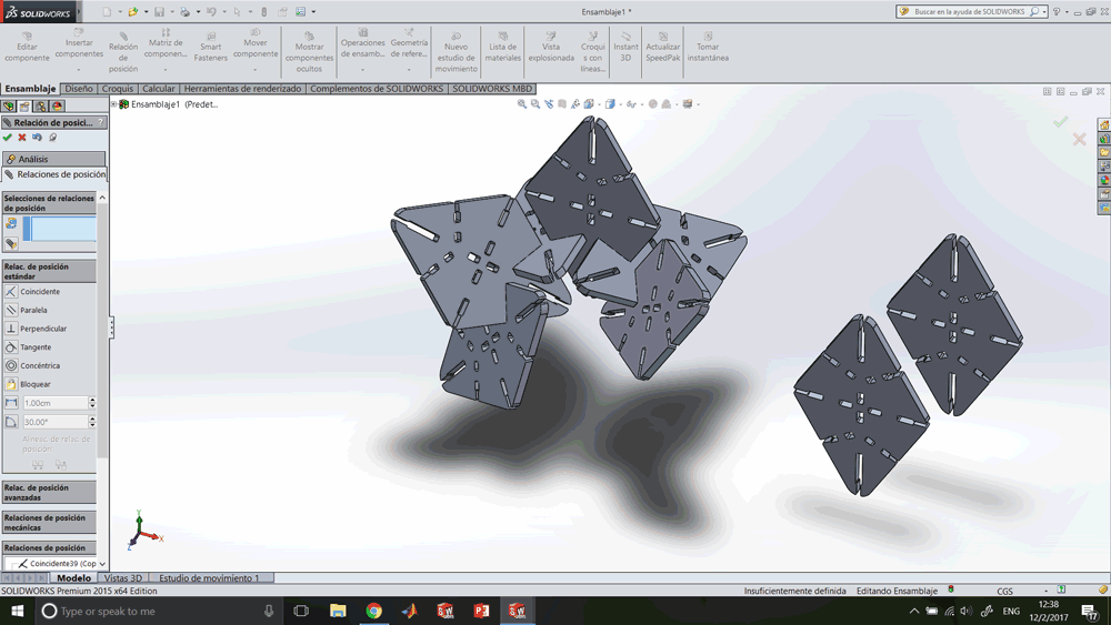
CAD
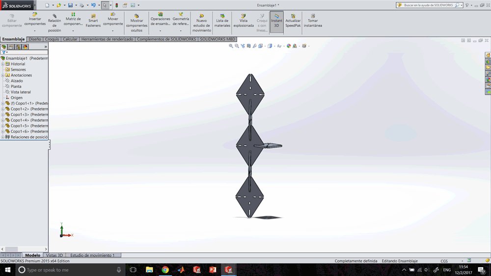
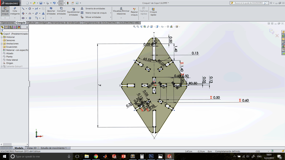
First I sketched only a quarter of the geometry and delimited its measure and position by using smart dimension that will allow me to change them later. Second, I completed the sketch by using symmetrical relations, that will change everything only changing the first dimensions. And finally I tested the assemble to get an idea of the posibilities.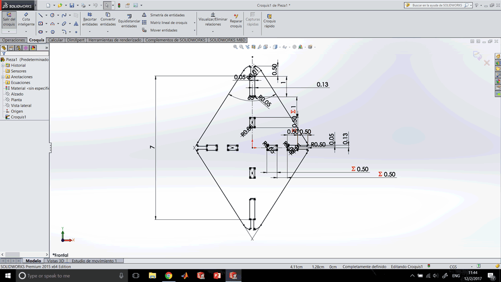
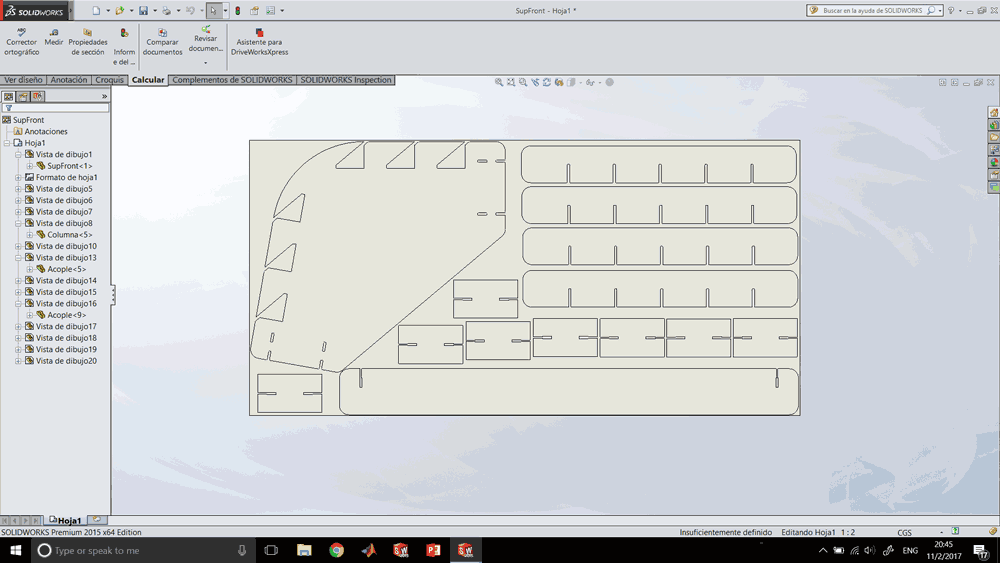
Nesting
I nested in the draft enviroment of SolidWorks, using a sheet with the size of the cardboard that we were going to cut.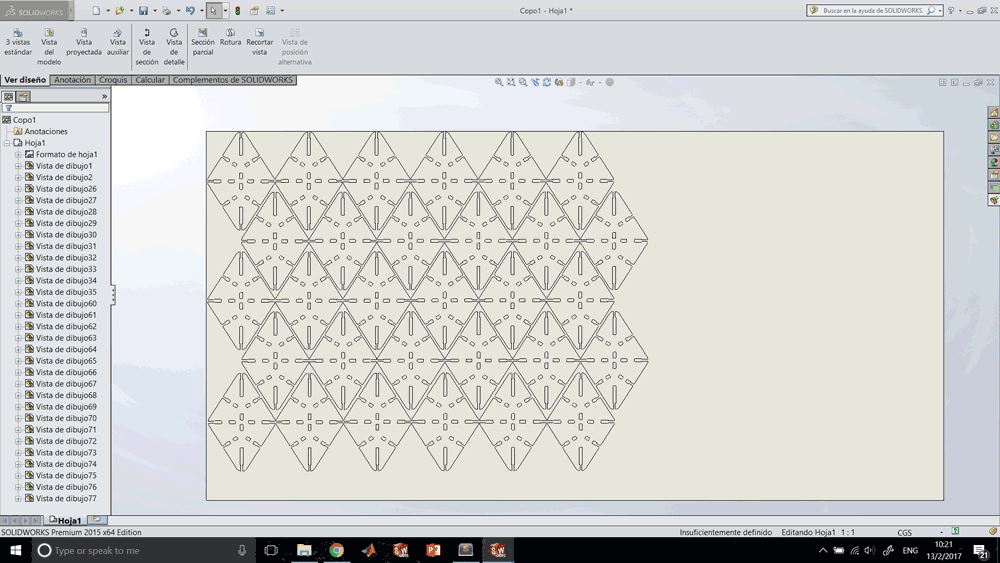
Cutting
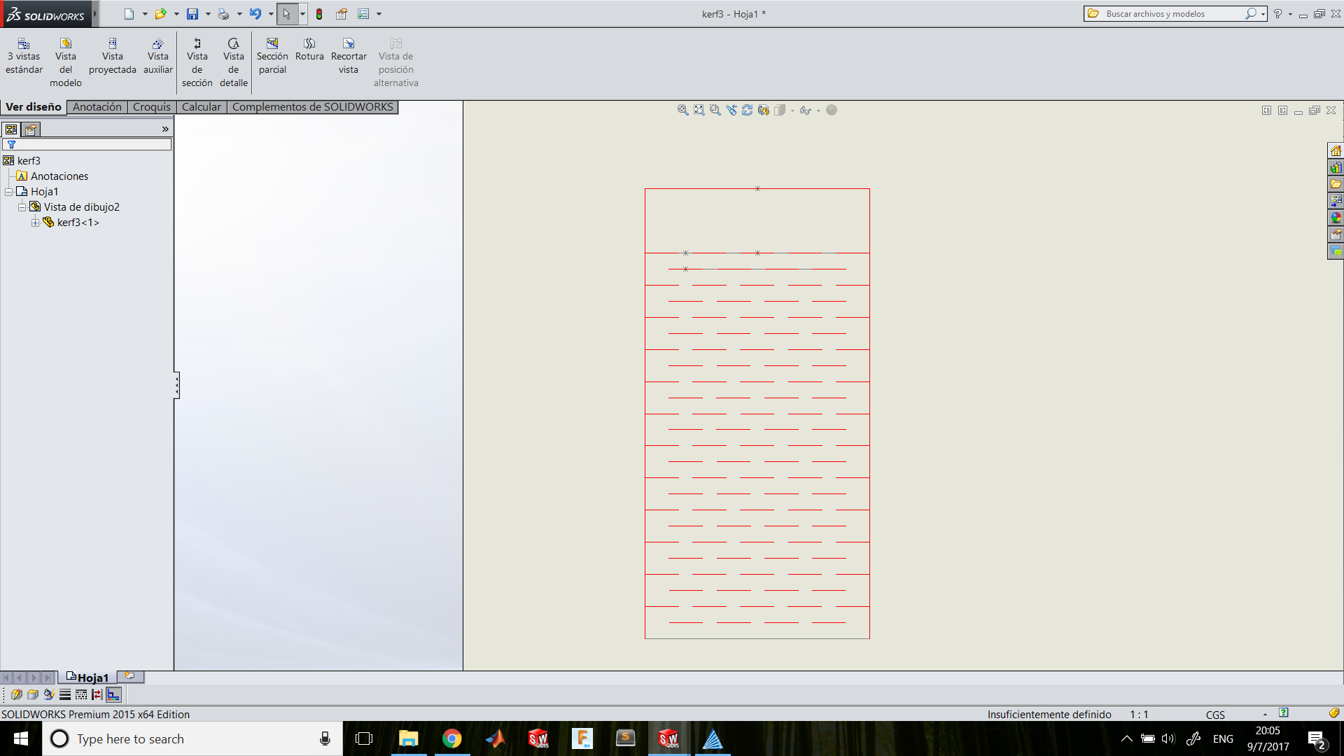
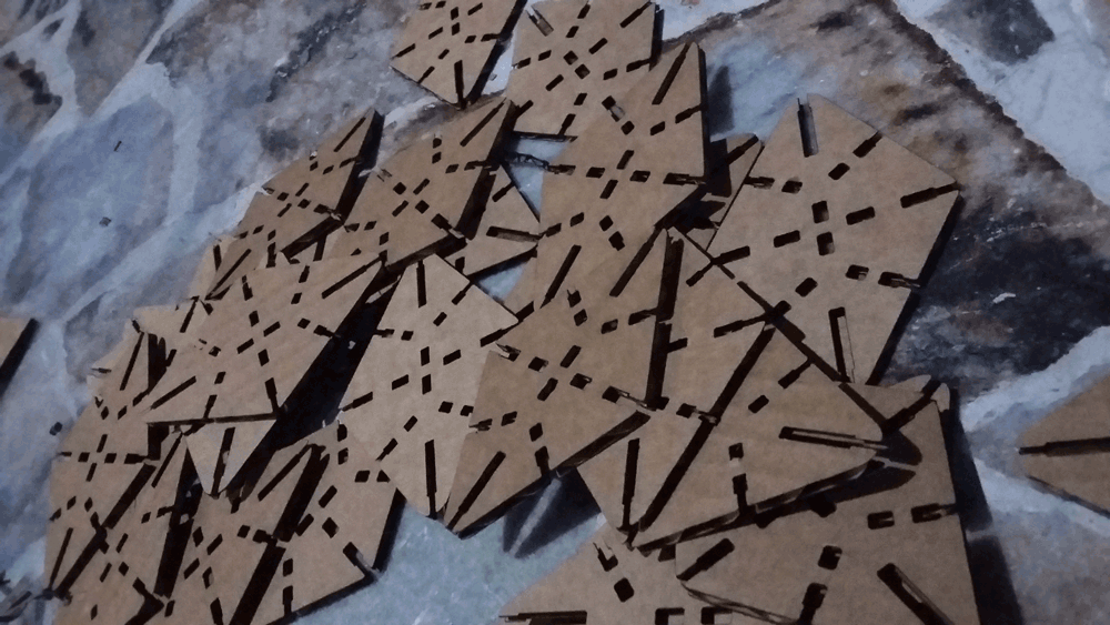
For cutting process I exported the draft into a PDF file and I imported to Corel Draw. Here I changed the line color to red, that means cutting line. Then I setted the parameters on the software by defining the material: Cardboard. And finally I placed the cardboard on the machine and let the machine making its work.
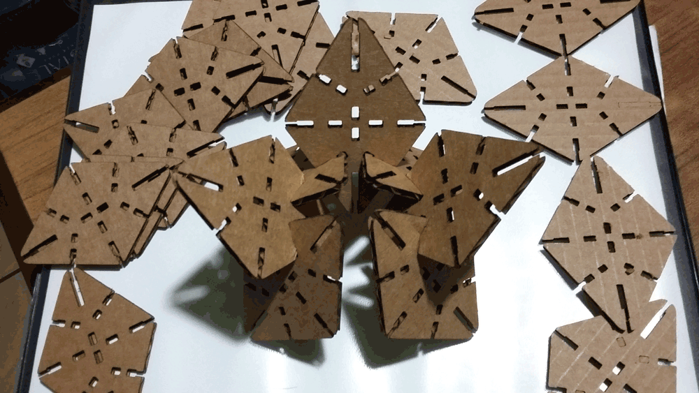
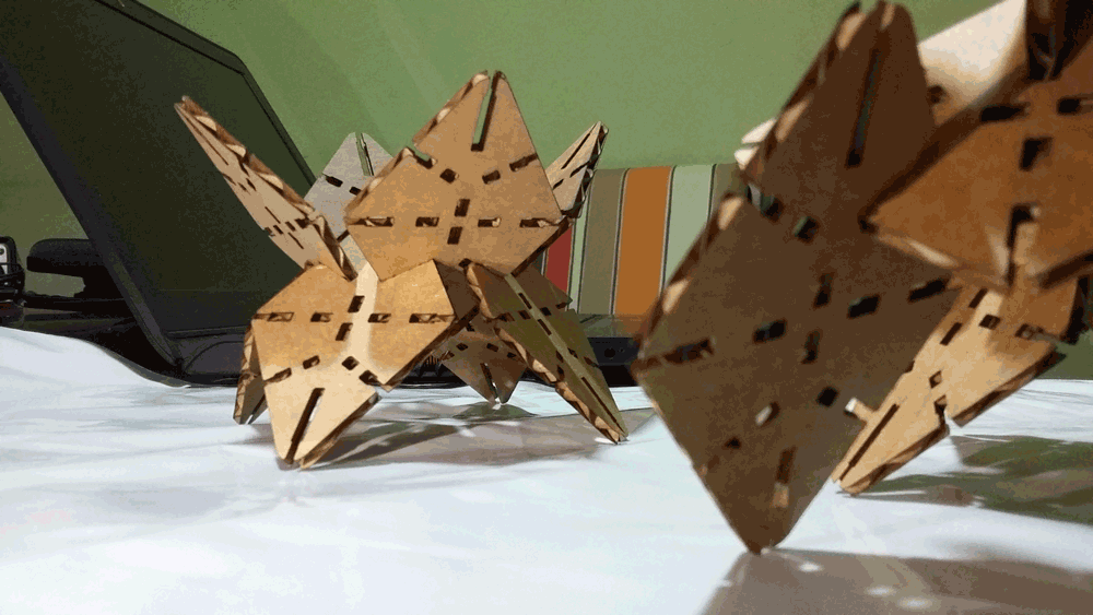
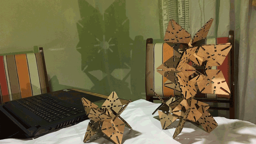
Assembling
Finally, for the assembly process I took off all the pieces and I started experimenting with the positions of the modules.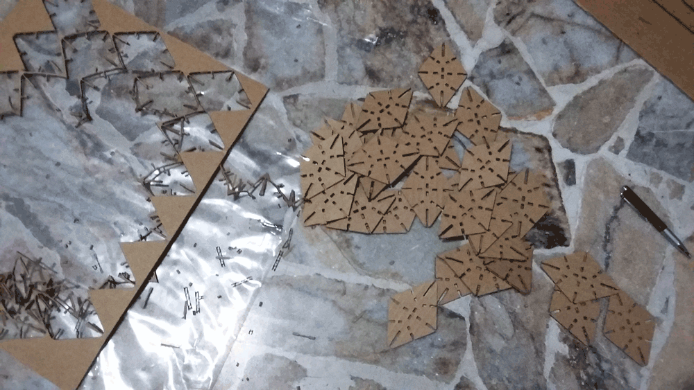
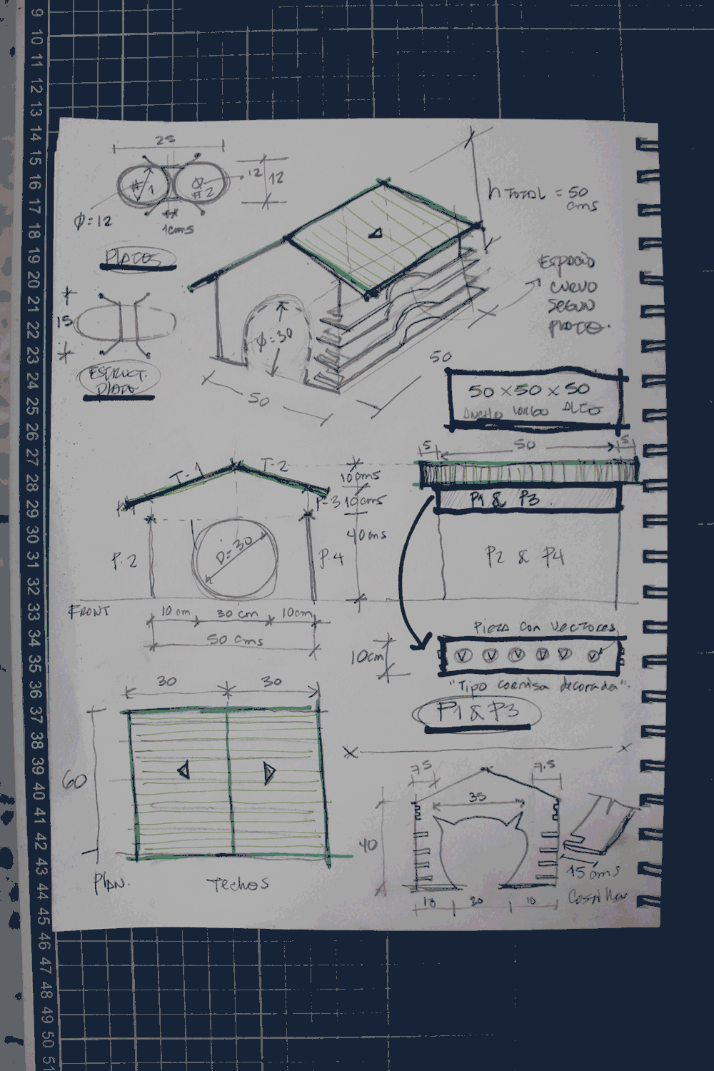
Laser Cutting Project
CAD
First we made 2D sketches and defined measures of the house of our official pet of Fab Academy's El Salvador Team: Pepper. You could see her later.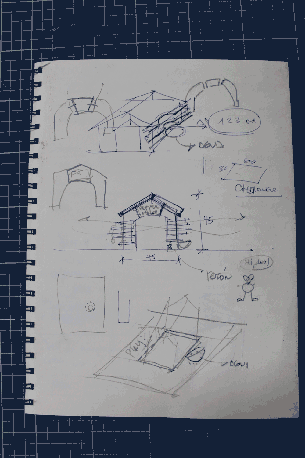
We also needed to make some test of the assembly process.
Modelling and assembly
And finally nesting
Laser Cutting
The laser cutter and engraving machine used for this assignment is a CO2 Trotec Speedy 100 with 600x300 mm or 24x12” work area. Once we had all the pieces nested in SolidWorks in 600x300 mm sized pages, we start to cut all in 3mm cardboard sheets.First step is turn the power on and wait until the chime indicates the machine is ready, for cutting purposes we used the aluminium honeycomb inside and proceed to calibrate the material.
Next step is open the PDF files in CorelDraw, and change the color outlines to RGB red (R 255, G 0, B 0) and the thickness to “thin” or 0.011 pt. To send the files to be cut is just necessary to send them via printer driver to the laser machine and define the size and material you are going to work with. The software controlling the laser is JobControl, here is a large material database and other necessary settings.
To cut 3mm cardboard we try several power and speed amounts and the one which worked the best was Power 70.0 and Speed 3.0 using 5000 Hz, 1 pass and the air assistant off because if we let it on, the cutting edges were burned.
To assembly Pepper Box house we used 10 cardboard sheets.
Assembly
Below you will enjoy a very nice video documenting the process of assembling Pepper's house.The protagonist of the video is Pepper (obviously), because so far many will wonder who is and how is Pepper?
So we invite you to spend a good time and know a little more about this nice exercise where the task of assignment served to demonstrate that the digital manufacture based on parametric design and manufactured in laser cutting can also contribute to do almost anything in our houses or offices; Even a home for our pet!
We hope the entire documentation process is of interest to you!.
Assigment 03-Assambly from Fablab Sv on Vimeo.
Vinyl Cutting
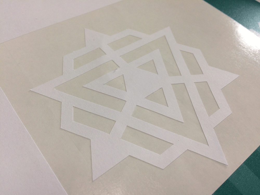
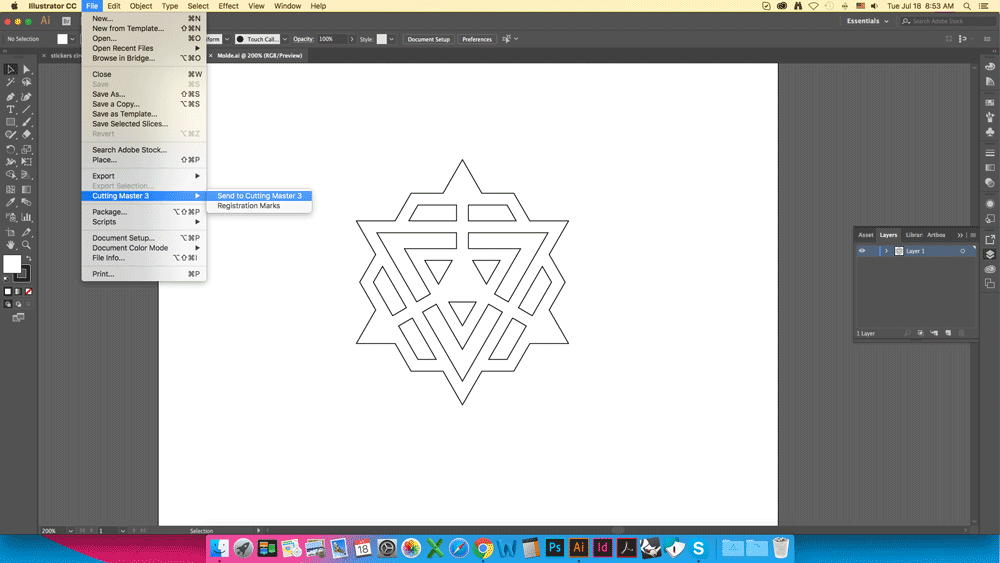
I decided to use the same shape as Week 12 to make a sticker
Open it on Adobe Illustrator and go to File > Cutting Master 3 > Send to Cutting Master 3
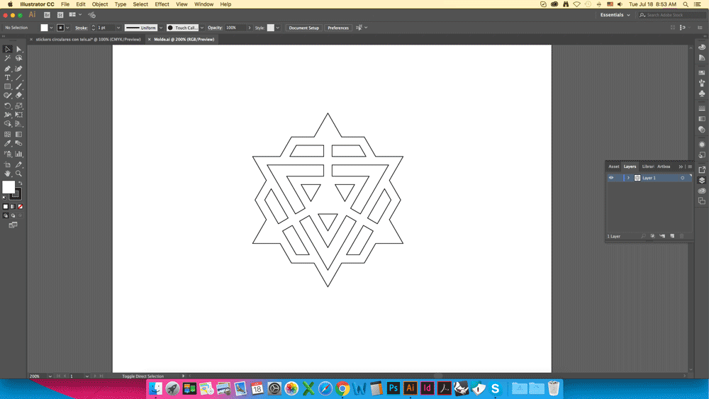
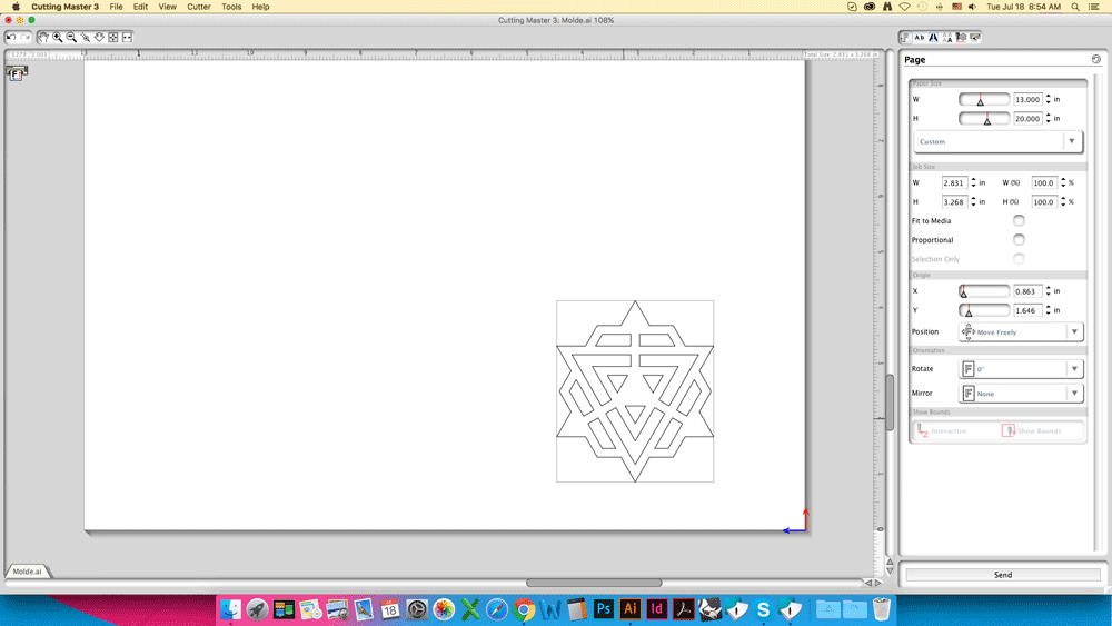
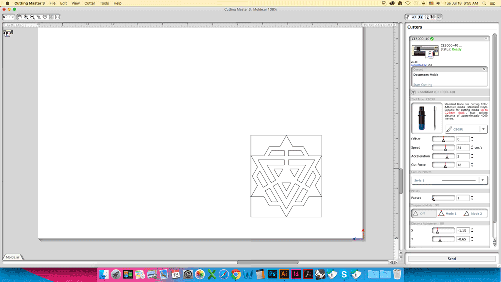
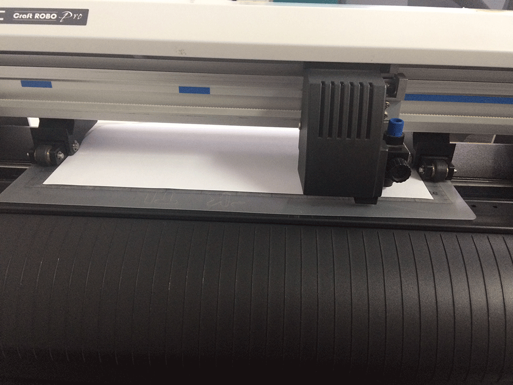
This is the result