This week we are going to make board that will communicate in a network
Designing the Boards
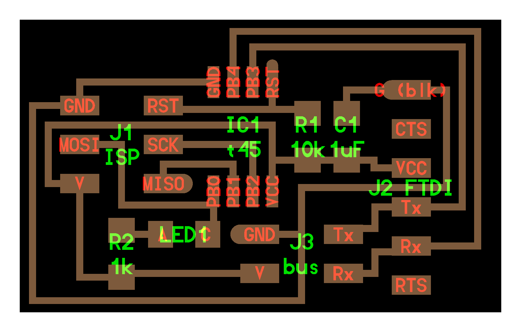
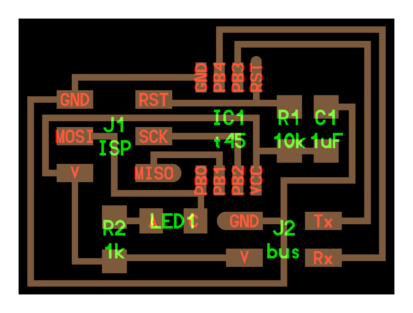
I follow the same process as Week 6 using Eagle and routing by hand
In this step we need to add components by typing add and we could choose them from a list part. We also could make change of position by dragging them, change of value or name by typing the respective command.
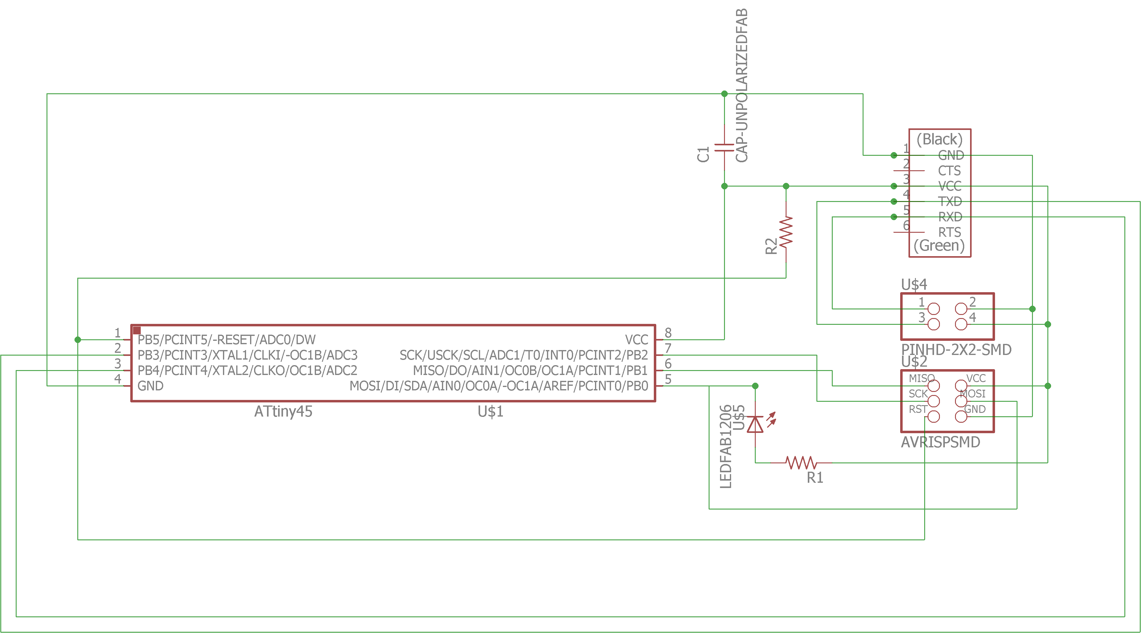
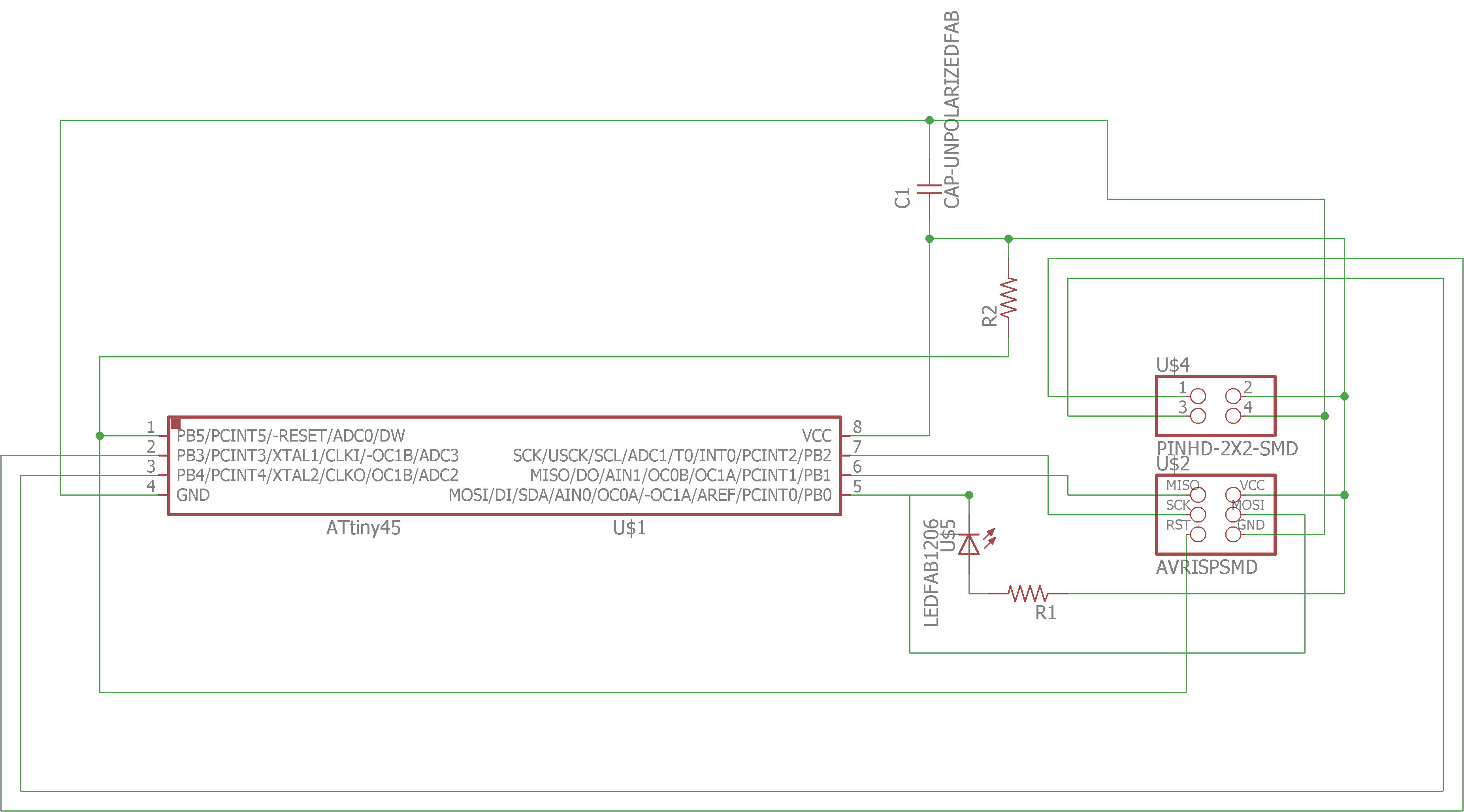
On this enviroment we can place elements dragging them, we can also rotate them typing rot and clicking or dragging them to the desire angle. We have to type route and clicking one pad and this will show to which pad is connected, you can select between different types of lines and nodes; and we can delete a wire writting ripup and clicking it.
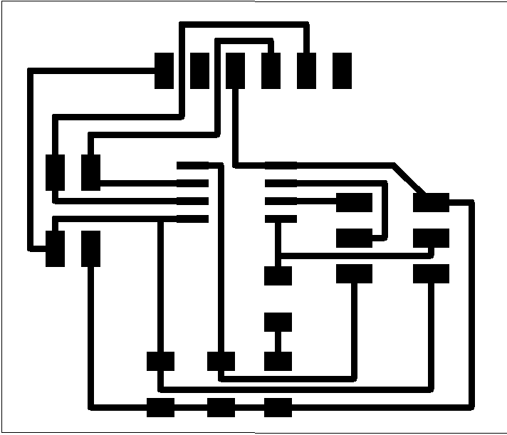
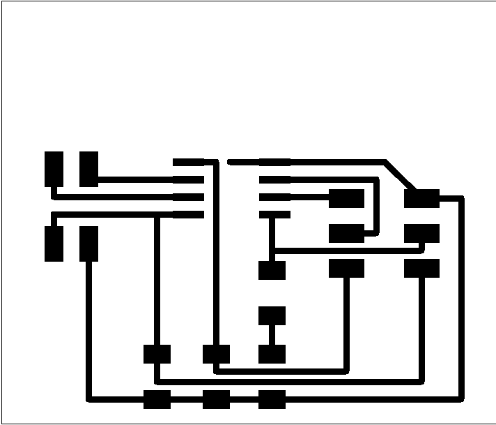
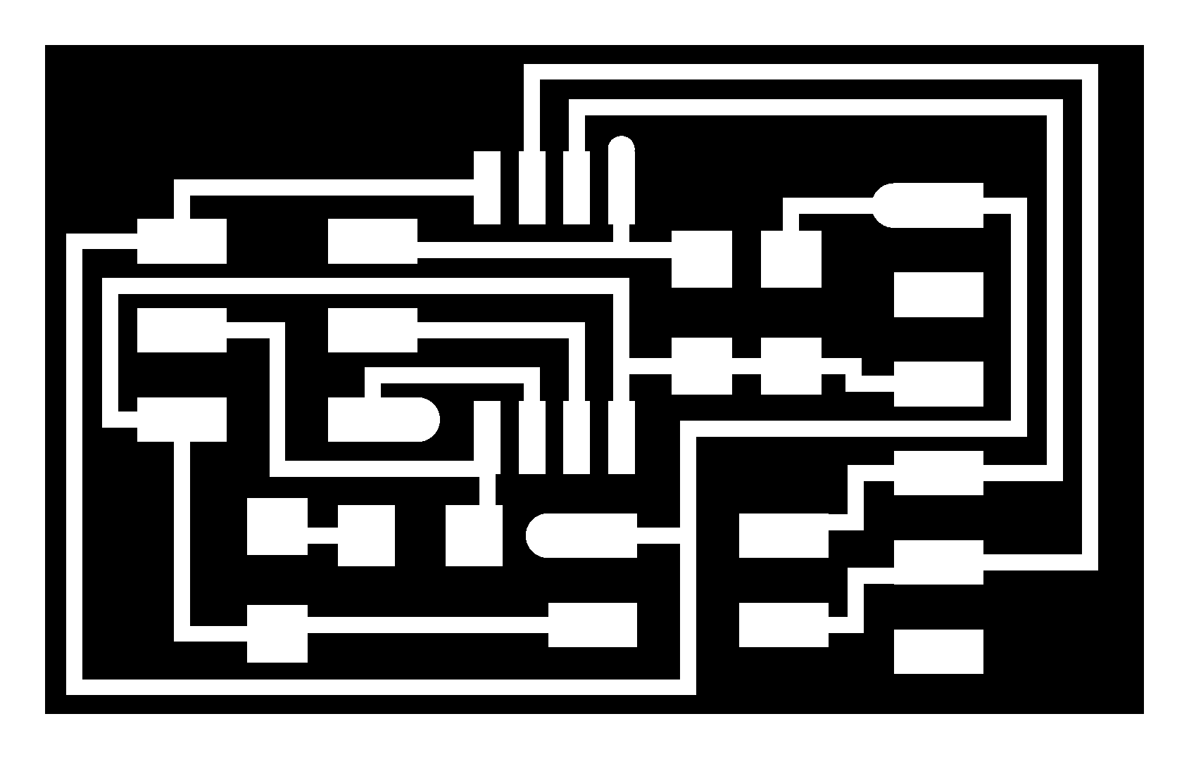
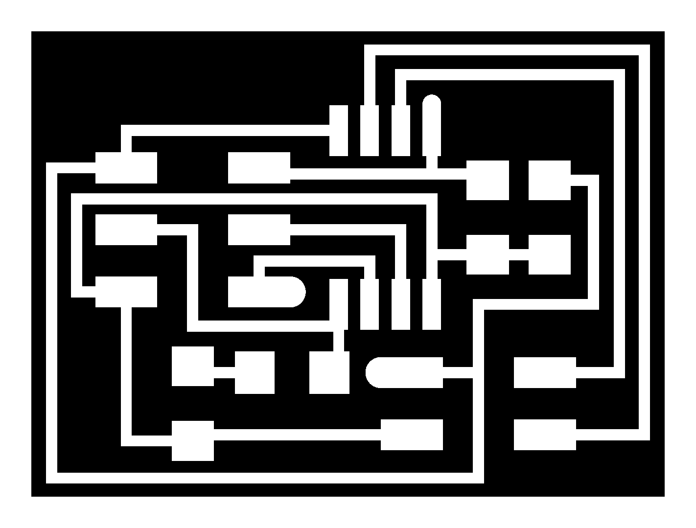
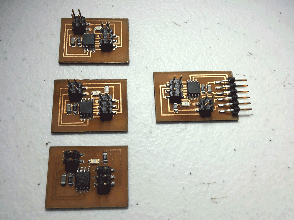
Making the Board
I follow the same method and steps as Week 6 to make boards that will use Serial Communication to talk between them (You can select anyone you want from Fab Academy web site)
Programming the board
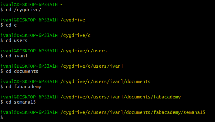
I have to say that you could program the board from Arduino IDE or from your OS Terminal (You need to instal Cygwin Terminal for Windows).
I used the second way, and what we have to do first is download C file and Make file from Fab Academy web site. I decided to program a Thermistor so I had to download its respectives files.
But before doing anything it's better to understando what we are doing.
Now that we know that, this is the make file that we need to use on Windows, bold lines indicate the changes I needed to do to work. If you are working on Mac or Linux you need to erase those changes.
PROJECT=bus
SOURCES=$(PROJECT).c
MMCU=attiny45
F_CPU = 8000000
CONFIG = C:/Program\ Files\ \(x86\)/Arduino/hardware/tools/avr/etc/avrdude.conf
CFLAGS=-mmcu=$(MMCU) -Wall -Os -DF_CPU=$(F_CPU)
$(PROJECT).hex: $(PROJECT).out
avr-objcopy -O ihex $(PROJECT).out $(PROJECT).c.hex;\
avr-size --mcu=$(MMCU) --format=avr $(PROJECT).out
$(PROJECT).out: $(SOURCES)
avr-gcc $(CFLAGS) -I./ -o $(PROJECT).out $(SOURCES)
program-bsd: $(PROJECT).hex
avrdude -p t45 -c bsd -U flash:w:$(PROJECT).c.hex
program-dasa: $(PROJECT).hex
avrdude -p t45 -P /dev/ttyUSB0 -c dasa -U flash:w:$(PROJECT).c.hex
program-avrisp2: $(PROJECT).hex
avrdude -p t45 -P usb -c avrisp2 -U flash:w:$(PROJECT).c.hex
program-usbtiny: $(PROJECT).hex
avrdude -p t45 -P usb -c usbtiny -U flash:w:$(PROJECT).c.hex -C $(CONFIG)
program-dragon: $(PROJECT).hex
avrdude -p t45 -P usb -c dragon_isp -U flash:w:$(PROJECT).c.hex
These changes are because sometimes (in my case) make couldn't find the configuration file, so we have to help it.
The C file that is on the FabAcademy web page verify which node are you talking to, through the serial monitor of Arduino, all boards blink at the same time, but only the board you are talking to, blink once again.
To program this C code on the board we need to follow this steps:
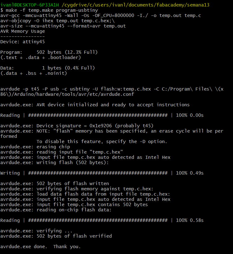
ID MIGHT BE DIFFERENT!
Speaking to the Network
We are using asynchronous communication, this means that the start and end of the communication is not syncronized or driven by a clock signal; instead in this communication the syncronization is given by synchronization signal, that is information that says to the other device that is about to receive data, and then, similarly, it receive information to stop the communication and prepare for the next start signal.
For this we need to:
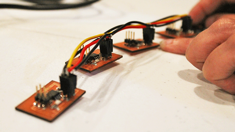
Results
Sponsors