This week we are going to make a board and the programation of an output device
Designing the Board
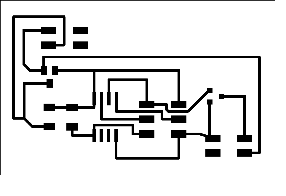
I follow the same process as Week 6 using Eagle and routing by hand
In this step we need to add components by typing add and we could choose them from a list part. We also could make change of position by dragging them, change of value or name by typing the respective command.
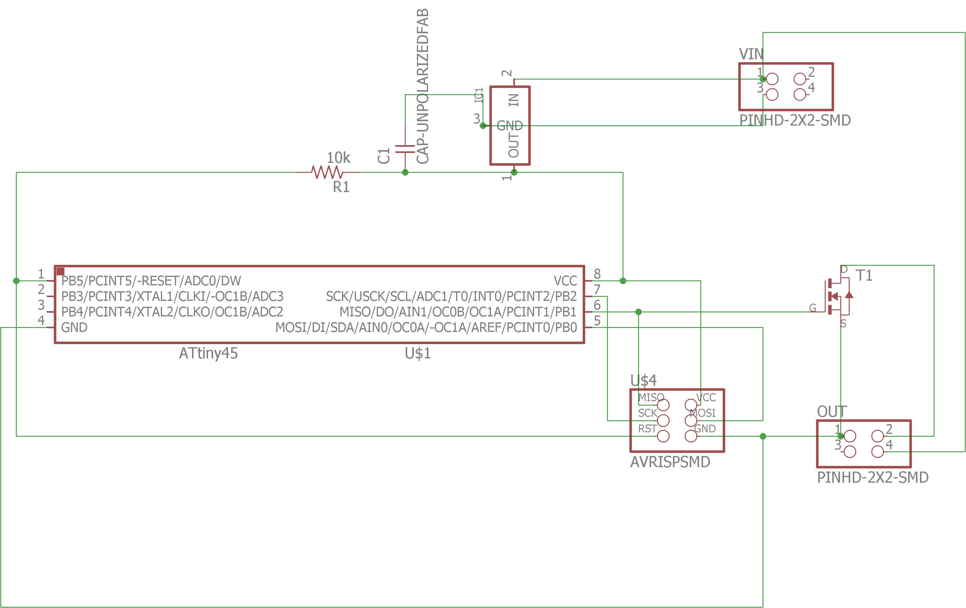
On this enviroment we can place elements dragging them, we can also rotate them typing rot and clicking or dragging them to the desire angle. We have to type route and clicking one pad and this will show to which pad is connected, you can select between different types of lines and nodes; and we can delete a wire writting ripup and clicking it.
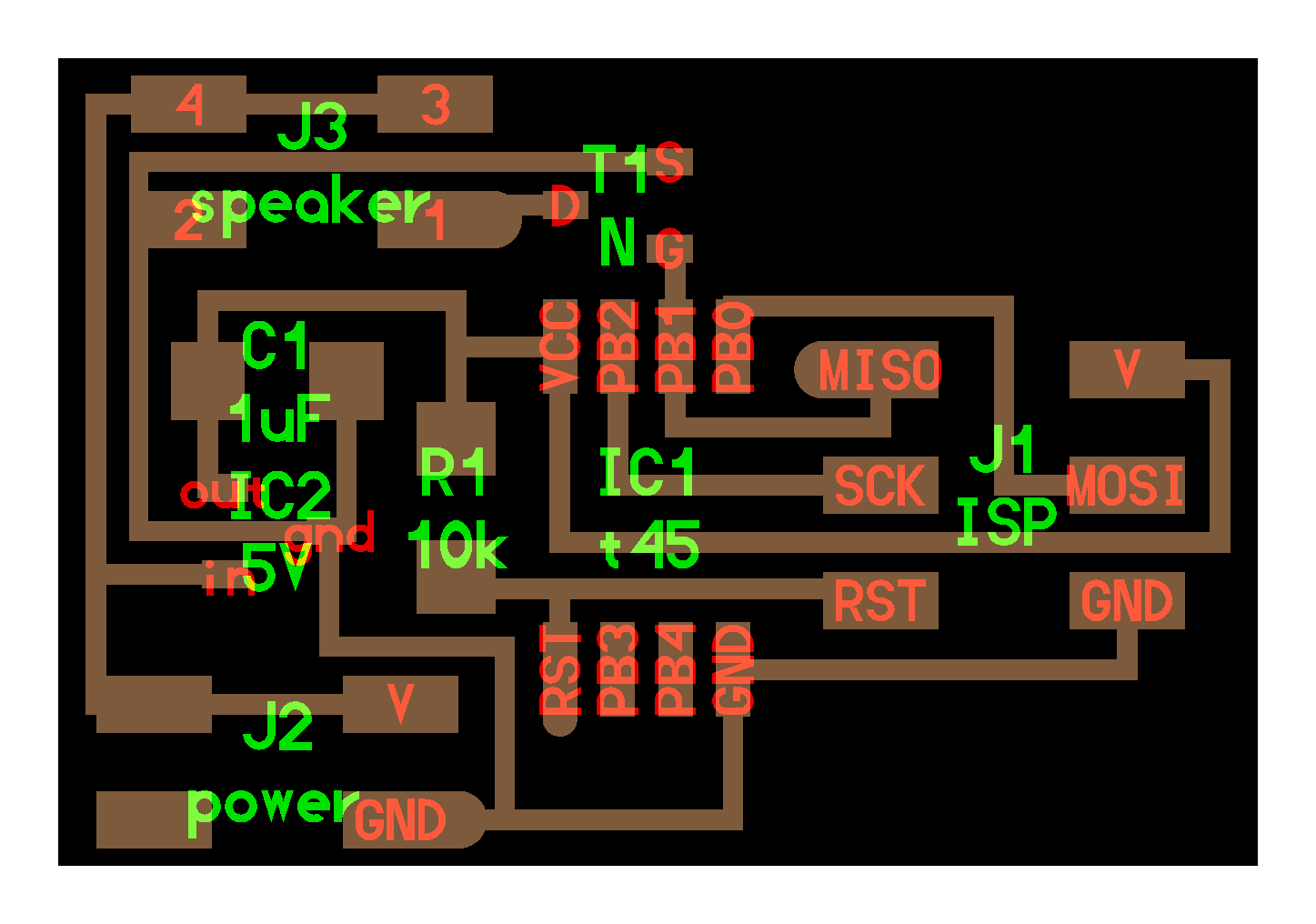
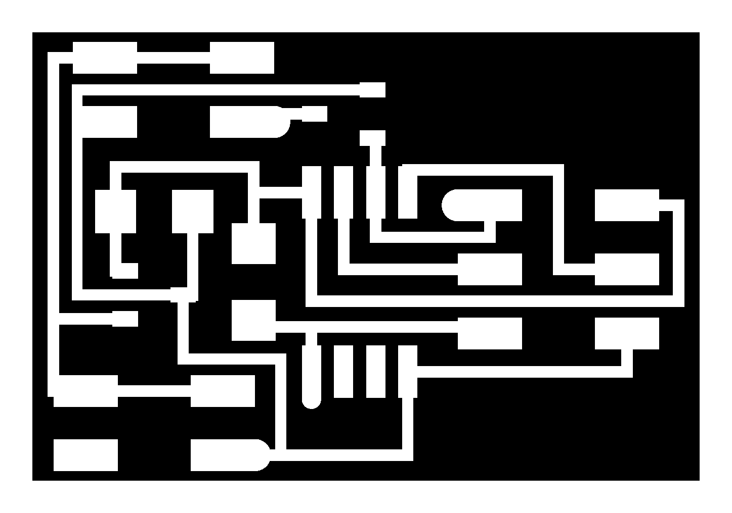
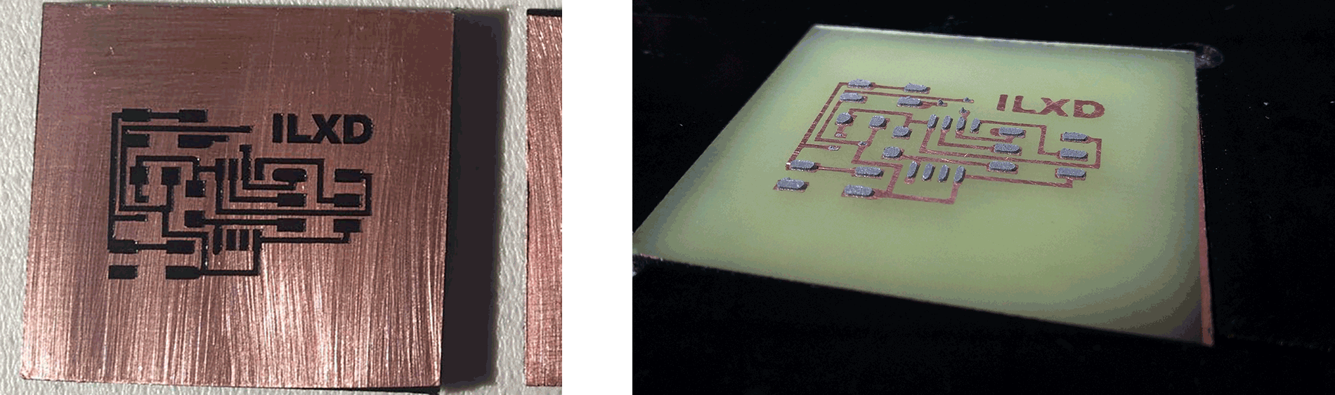
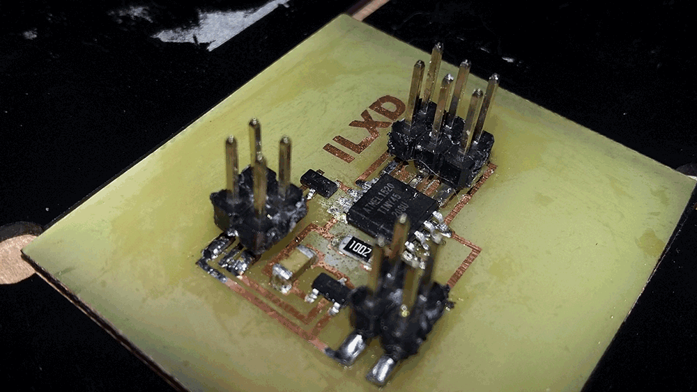
Making the Board
I follow the same method and steps as Week 6 to make the board to control a speaker (You can seleect anyone you want from Fab Academy web site)
Programming the board
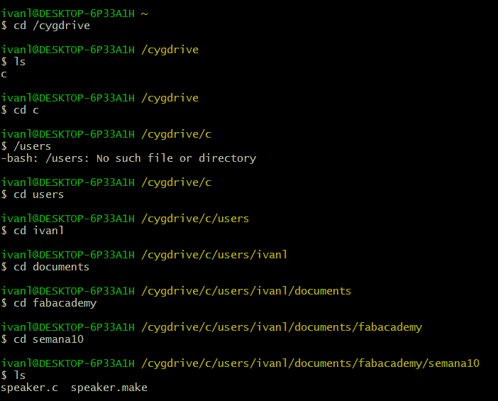
I have to say that you could program the board from Arduino IDE or from your OS Terminal (You need to instal Cygwin Terminal for Windows).
I used the second way, and what we have to do first is download C file and Make file from Fab Academy web site. I decided to program a speaker so I had to download its respectives files.
But before doing anything it's better to understando what we are doing.
Now that we know that, this is the make file that we need to use on Windows, bold lines indicate the changes I needed to do to work. If you are working on Mac or Linux you need to erase those changes.
PROJECT=speaker
SOURCES=$(PROJECT).c
MMCU=attiny45
F_CPU = 8000000
CONFIG = C:/Program\ Files\ \(x86\)/Arduino/hardware/tools/avr/etc/avrdude.conf
CFLAGS=-mmcu=$(MMCU) -Wall -Os -DF_CPU=$(F_CPU)
$(PROJECT).hex: $(PROJECT).out
avr-objcopy -O ihex $(PROJECT).out $(PROJECT).c.hex;\
avr-size --mcu=$(MMCU) --format=avr $(PROJECT).out
$(PROJECT).out: $(SOURCES)
avr-gcc $(CFLAGS) -I./ -o $(PROJECT).out $(SOURCES)
program-bsd: $(PROJECT).hex
avrdude -p t45 -c bsd -U flash:w:$(PROJECT).c.hex
program-dasa: $(PROJECT).hex
avrdude -p t45 -P /dev/ttyUSB0 -c dasa -U flash:w:$(PROJECT).c.hex
program-avrisp2: $(PROJECT).hex
avrdude -p t45 -P usb -c avrisp2 -U flash:w:$(PROJECT).c.hex
program-usbtiny: $(PROJECT).hex
avrdude -p t45 -P usb -c usbtiny -U flash:w:$(PROJECT).c.hex -C $(CONFIG)
program-dragon: $(PROJECT).hex
avrdude -p t45 -P usb -c dragon_isp -U flash:w:$(PROJECT).c.hex
These changes are because sometimes (in my case) make couldn't find the configuration file, so we have to help it.
The C file that is on the FabAcademy web page is a random sound generator by PWM (Pulse Width Modulation), on this way to produce sound we need to modify the delay to modify the pitch and the quantity of cycles to modify the duration.
To program this C code on the board we need to follow this steps:
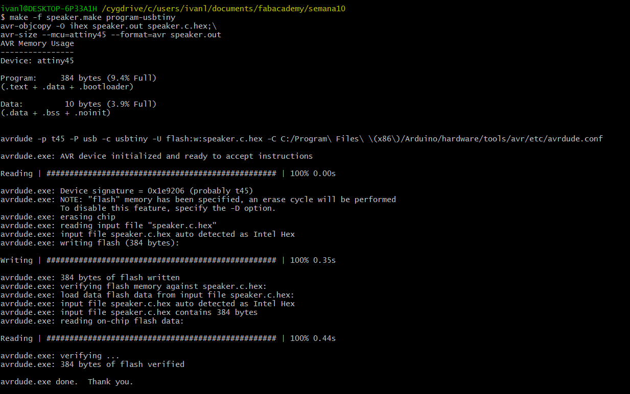
Results
I continued making changes to the code and finally I could play this song:
Week 10 - Output Devices from Ivan López on Vimeo.
Sponsors