Alejandro, 22, born in Cusco - Perú. Just obtained my bachellor degree in industrial engineering at University of Lima. I've been passionate in science since I was at school and I've always wanted to be part of a new innovative field
Fab Academy has presented me with a great opportunity to learn about digital fabrication and is giving me the tools and knowledge of how (almost) everything is made. I really hope to take the greatest benefit of the course in order to contribute to the society and the world. That's my greatest goal!
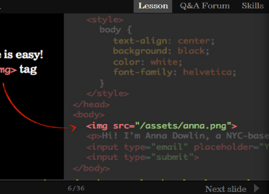
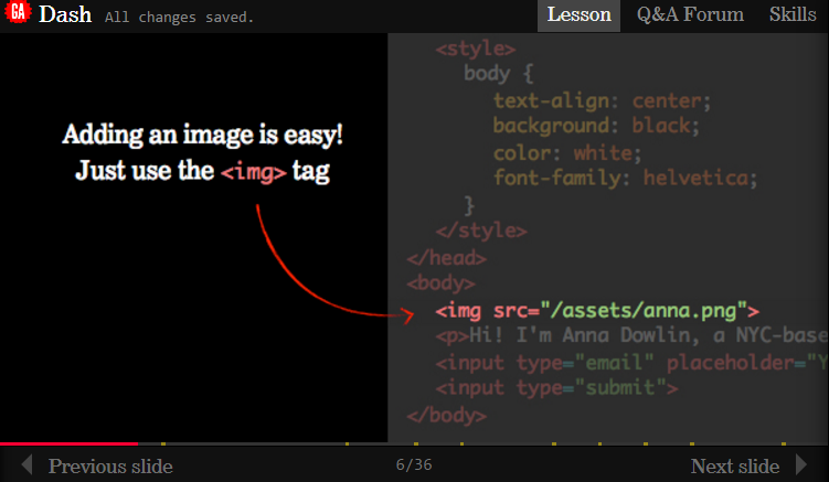
It was a little tricky at the beginning, but soon I get the catch. I started doing some HTML5 tutorials from the page: dash.generalassemb.ly. It has some really helpful tutorials to master your skills in HTML5 and CSS3.
I wrote a couple of scripts and move on to the next step: Chosing the ideal IDE for the development of my Web.
Fig2. - A slide of dash tutorial
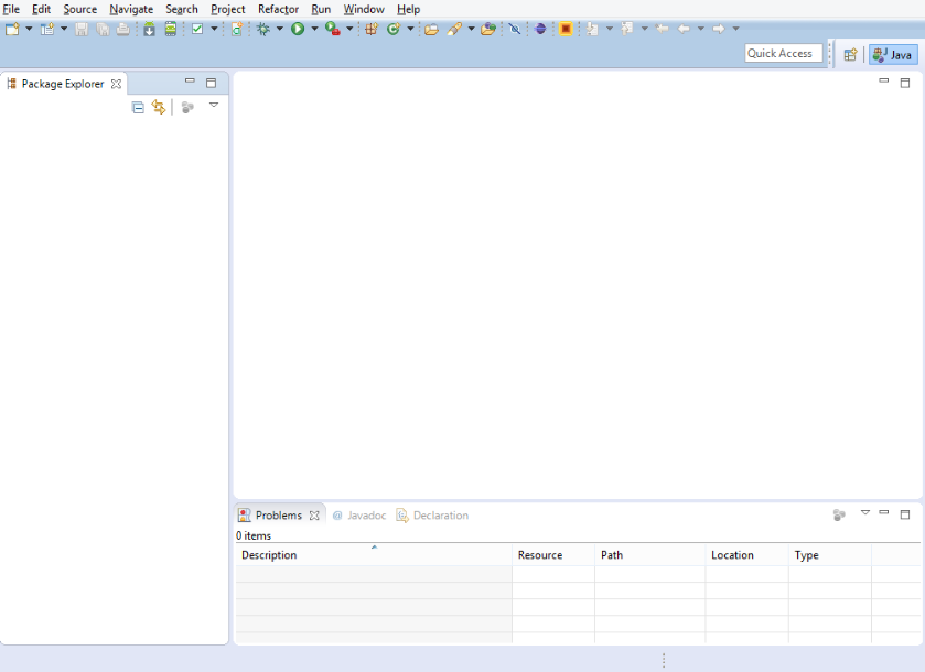
After giving a try with multiple environments and text editors like sublime, Netbeans, Bluefish, Eclipse and Maquetta, I finally decided for Eclipse. It felt really confortable to work with and I was provided with multiple tutorials to get in use to
the interface. It has also been in the market for quite a long time, so it's actually reliable.
Fig3. - Eclipse IDE.
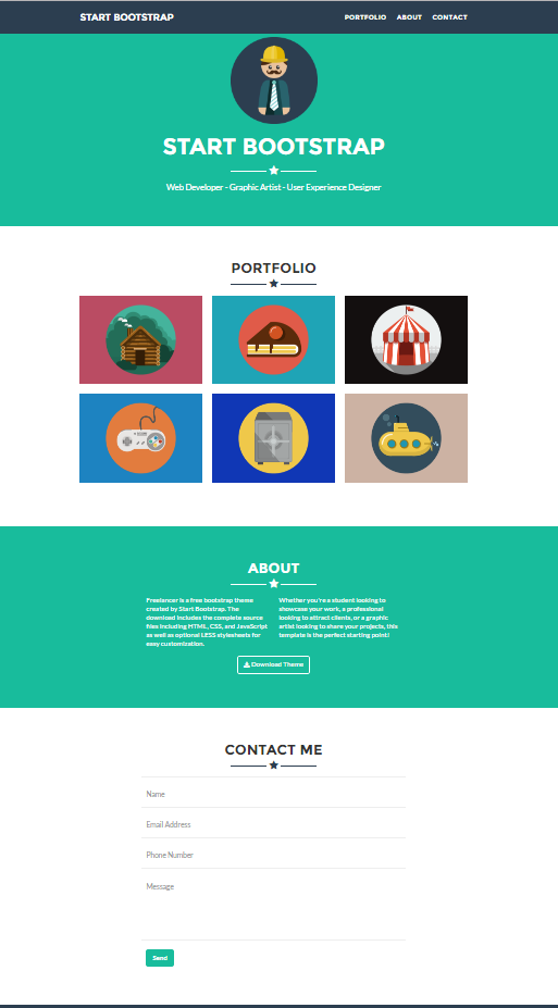
I also spend quite a time chosing an appropiate template for the site. Finally decided to use a free downloadable one called Freelancer. from Bootstrap.
Fig3. - The template I chose.
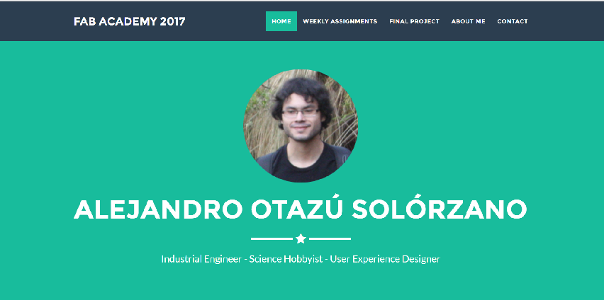
And finally, I wrote my own HTML5 script, put some images and personilized my site :)
Fig4. - Index page of my website
GIT
In order to push the repository we need to follow some steps
First of all, we need to download GIT, wheter for windows, linux or mac it works.
As I use windows, I'll be using GIT bash
Fig5. - Git bash
Then, this caption screen will show
Fig6. - Git interface
Finally, you need to push the repository to the web, to do that you follow this set of instructions:
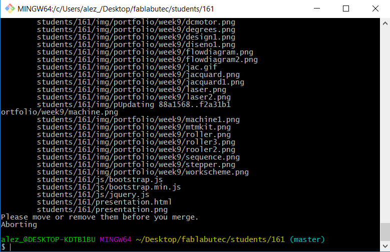
Type in: git pull - This allows to pull all data from the repository to your local repo
Fig7. - response for git pull
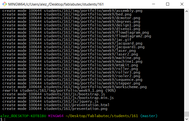
Type in: git add . - This allows to add changes in the local
Fig8. - response for git add .
Type in: git status - This allows to see the changes in the repository
Fig9. - response for git status
Type in: git commit -m "comment" - Allows to register the actualisation
Fig6. - response for git commit -m
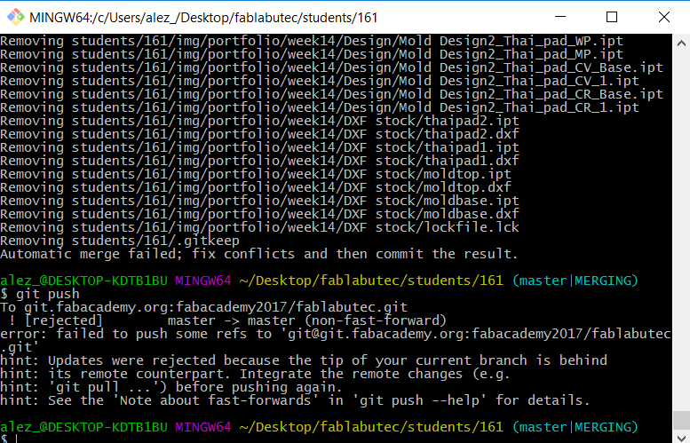
Finally, type git push to update changes on your repo.
Fig6. - response for git push
Final project idea
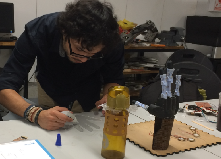
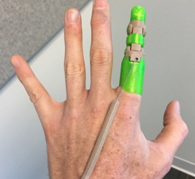
I was always passionate of sports, martial arts and everything the human body can acheive. The past 6 months I get to know a kid who was missing his right hand.
He was also passionate for martial arts as well as me, but for his condition, couldn't expect to acheive that much. By that time I was still a university student
and doing my internship at the Automization Laboratory, where we had several 3D printers, software for 3D design and also, a couple of cnc machines. I wanted to
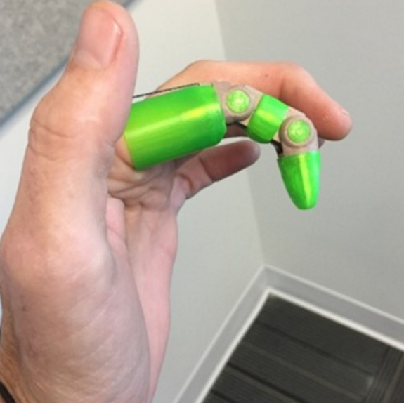
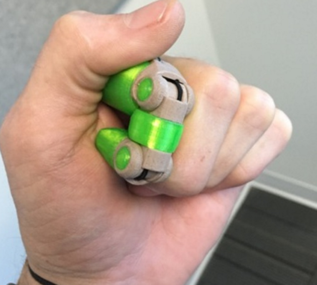
change this kid's life and used the technology I was provided with to acheive that. So I began to design a hand, starting from the fingers. but not just an aestethic hand.
A one that could restore almost the complete function of the human body.
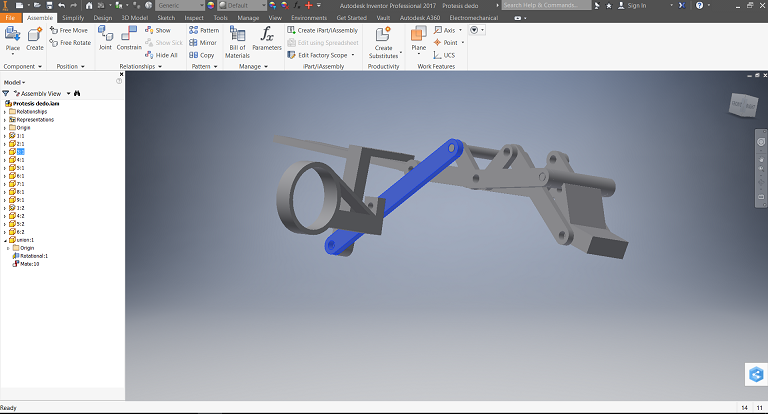
I worked several months using Autodesk Inventor to design multiple finger designs. Finally, almost at the same time I finished my career, I finished a finger for the kid !.
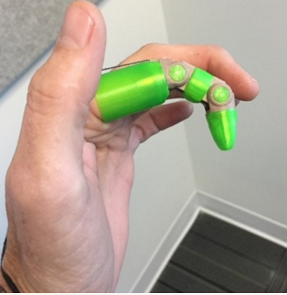
It was one based on Knick's prosthetic finger from Thingiverse, I made a couple of adjustments with the calipper and the kid to obtain the final version.
Fig3. - Prosthetic finger.
That was one of my main motos to join the Fab Academy as soon as I finished university. The idea of creating things that could change people's life.
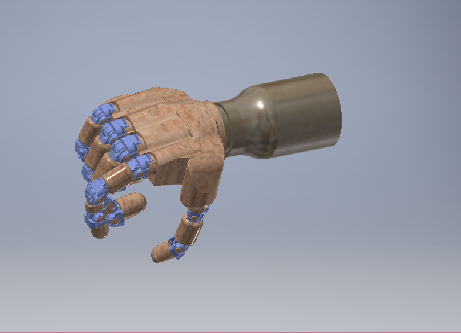
The idea of applying the knowledge I obtained in my university life and internships as well as everyday experiences made me believe that everything was possible. So my Final Project
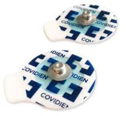
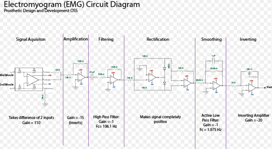
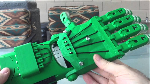
WILL be a fully functional prosthetic hand for the ones who need it. A hand that will work with the muscular pulses people use to move their own hand, finger by finger. I've already looked
at the hardware I'll need (some myosensors,filters, a microcontroller and some more components) and I'm more motivated than never !
Project plan
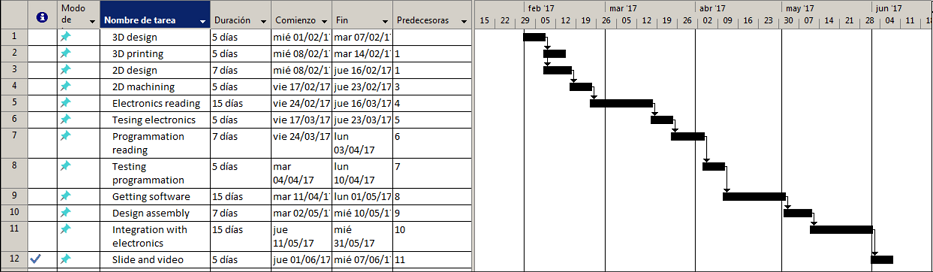
I have an idea of how the project is going to be developed throughout the Fab Academy period. I made a gantt diagram to plan
step by step, integrating the most parts I can, including some weeks for researches.
For this week, I used Autodesk inventor And Solidworks for the 2D design because I find that they offer the easiest way to do
parametric sketches, plus, I already have some experience using them and I am very Familiar with the environment
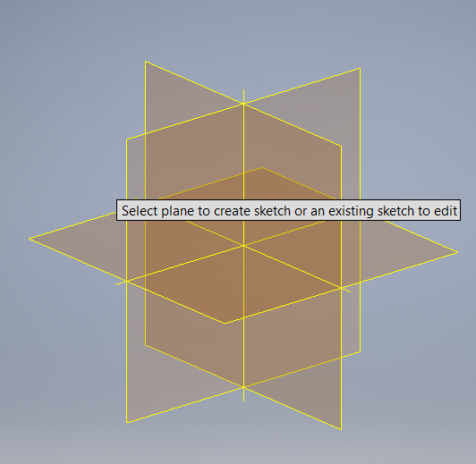
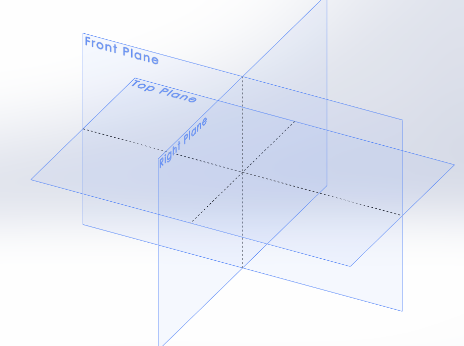
Starting with Autodesk Inventor, It allows to do 2D sketches in the "Sketch" tab. As it's a software for making 3D designs,
you must first select in which plane of space you'll work and do "new sketch"
Fig1. - selecting a plane in Inventor
Solidworks works in a similar way:
Fig2. - selecting a plane in Solidworks
The tools that these software provides for 2D sketching are the classic lines, circles and shapes. Both have a similar
interface and both are located in the "sketch" tab
Fig3. - 2D tools in InventorFig4. - 2D tools in Solidworks
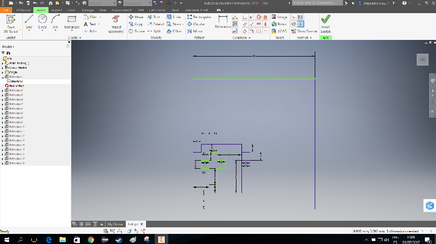
The workflow of 2D design in these softwares are simple, Select the sketch tool you wish, line for example
and start drawing your sketch. The dimentions you wish will be set inmediatly after placing the first line; then
continue with the next line making a connection. You end up having an sketch like this one:
Fig5. - 2D sketch in inventor
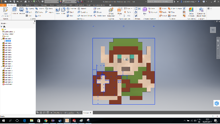
The last thing you need is imagination. You can now create the sketch you'd like with the tools provided.
Here's an example
Fig6. - Example of 2D sketch with a coloured finish
3D Design
I really enjoyed completing this Task. Each step was really entertaining. I always loved 3D design and already had some experience in it.
The first step was selecting the 3D software I'll be using to complete the design part of the project. So I tried many different tools and software
for that purpose.
The first one and my favourite was Autodesk Inventor. I was familiar with most of the tools and ways to 3D design in this software. Plus,
I got a free license as a former student of the university. During my internship I had to do many tasks which implied 3D design and I accomplished most
of them using this software.
I started designing the first phalanx of the prosthetic hand for my final project. This project needs a bunch of parts to be fully functional,
so I had to do it patiently. Here's my result.
Fig1. - Index finger phalanx drawn in Autodesk Inventor
It might still seem to be a shapeless solid, but soon it'll all make sense.
The next software I tried (already tried it before, but still wanted to remember) was Solidworks. I already had a bit of experience using this sofware
since I learned to use it during my internship, plus, I was provided a license. A license was provided by the Fab Academy this year, so there was no reason
for not to try this one too.
Tried to draw the same part here. Here's the result
Fig2. - Index finger phalanx drawn in Solidworks
Those are strong and versatile software and are very similar to work with. Personally I'm more confortable using Inventor over Solidworks, But again
it's just a matter of perception.
So far so good. Then, I wanted to use as many design software as possible. I love designing, so why not trying some drawing tools that actually are very
different from the ones I was used to
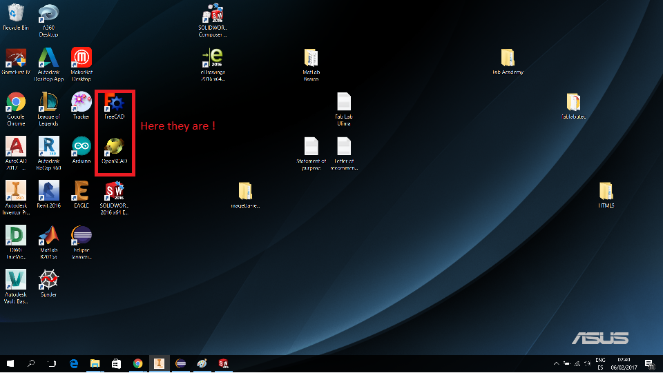
I downloaded 2 more design software to give them a try. Those where FreeCAD and OpenSCAD. Here's how my desktop looked like
Fig3. - Desktop with bunch of programs including FreeCAD and OpenSCAD
Man ! I found really tricky to get to use these ones. Those are off from the traditional design methods. My brain had to "reshape" in order to get something drawn.
To be honest. I couldn't draw the same part I did using Solidworks or Inventor. I decided to try to draw another part of the hand, a simpler one, so I tried
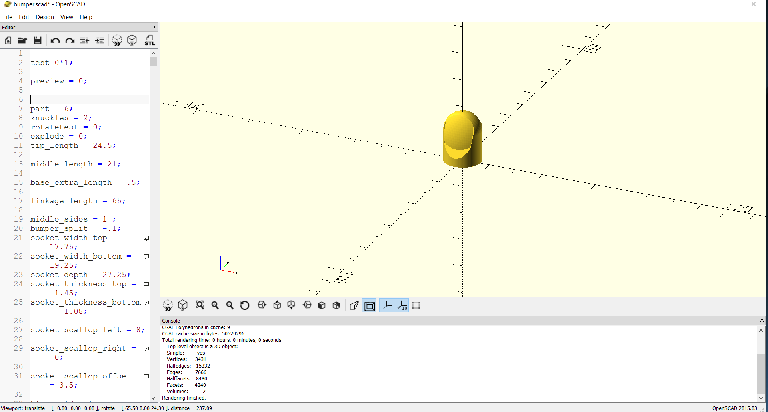
to draw the finger tip. Here's the result using OpenSCAD.
Fig4. - Finger tip drawn using OpenSCAD
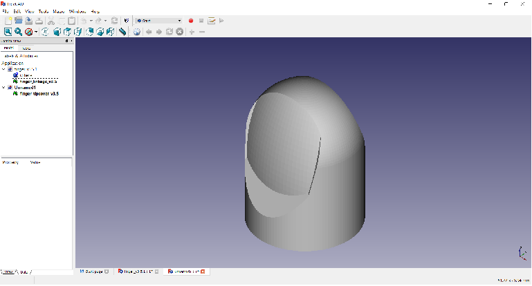
Once Again, I had difficulties using the FreeCAD.This one was (surprisingly) harder to use. To be honest, I couldn't get much done here so I have up trying (this actually
took me a long time). I saved some time so I could draw more of my parts in a more confortable evironment ( Call it Inventor :) ). But to try to get something done here. I imported the
SCAD file from OpenSCAD to see how it looked here. Here's what it looked like:
Fig4. - Finger tip as shown in FreeCAD environment
Finally. I finished 5 of the parts I need for my final project (using Inventor, of course).
Took a while, but I enjoyed every moment of making them, and still gonna enjoy making the last parts until I complete the assembly. Can't wait how it'll look !
Fig5. - Progress made this week
Update
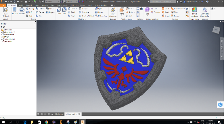
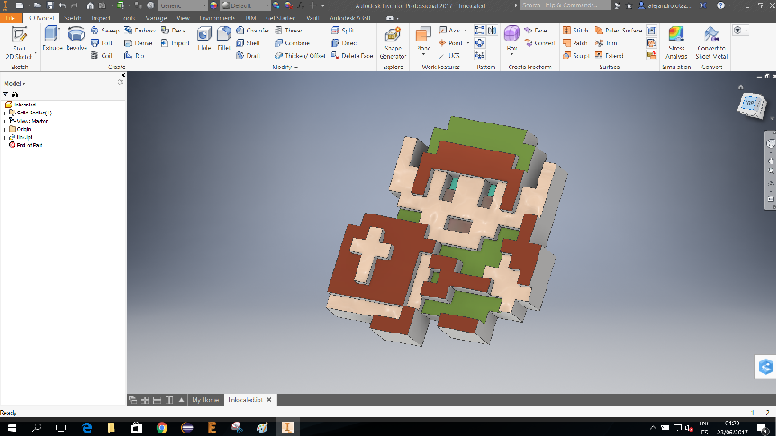
I made a lot of progress along the academy. Here are some designs using Inventor that I made for some assigments:
Fig6. - Hylean shield for moulding and castingFig7. - Link for moulding and castingFig8. - Pylon for composites
This week, we learned the use of computer-controlled cutting machinery, more specificly laser cutter and vinyl cutter machines so we learn how some industrial design products are made.
The laser cutting assignment was to make laser cutter parts, varying slot dimensions using parametric functions, testing the parameters and cutting settings. The pieces must be parts of an assembly using
press-fit principles. And the vinyl cutting assignment was to draw something that will be cutted and used in something using the vinyl cutter.
Laser cutting
The laser cutter uses Corel Draw to input the parameters of the cut, to import the image to be cut and set the position and controll the workspace. So, in order to import the files to the software the
image had to be friendly with corel. Luckily, a Corel works with a lot of files extensions for 2D drawing such as .AI (Adobe ilustrator), .BMP (windows bitmap), VSD (visio), .CDR (The proper corel extension),
.dwg and dxf (autocad drawing and interchange format), .PDF, .jpg and many others
Provided all these tools, it wasn't hard to decide which one I'd use. As I said before. I feel really confortable using Autodesk Inventor for 2D and 3D drawing. Plus, it allows to generate 3D sheets that simulates different materials
and make an assembly from them to test the actual parameters and sizes. so I opted for it.
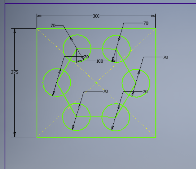
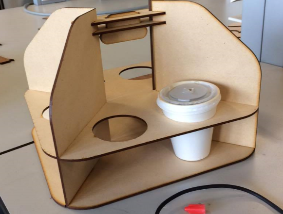
The next part was to decide what to design. It had to be a parametric press-fit construction. I wanted my design to be a puzzle-ish set of parts that together make something useful. That can be used in everyday life. Drinking my daily
cup of coffee I got the idea.
Fig1. - Idea
The Design
As I mentioned, I used Inventor for the design as it allows to give parameters and dimentions.
I started drawing the sketch of the first part:
Fig2. - Step 1
Then, I drew the sketch with the parameters for 5mm wide mdf
Fig3. - Step 2 set parameters
Then, turn it 3D so we have the final design for the part.
Fig4. - Step 3 give the 3D finish
Then, we make the press fit holes giving the same parameters for the width of the mdf.
Fig5. - Step 4 give the finish and export face
Then, turn it 3D so we have the final design for the part. In order to have the cutting files ready, we need to export each face or sketch with .DXF format
Fig6. - Step 3 give the finish and export face
We repeat the same workflow for the rest of the parts
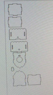
Fig7. - Design of the rest of the parts
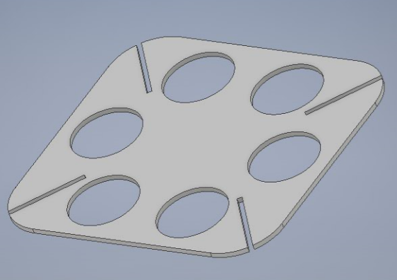
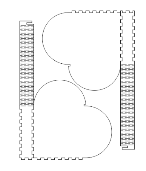
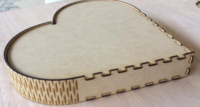
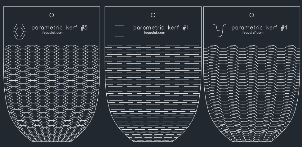
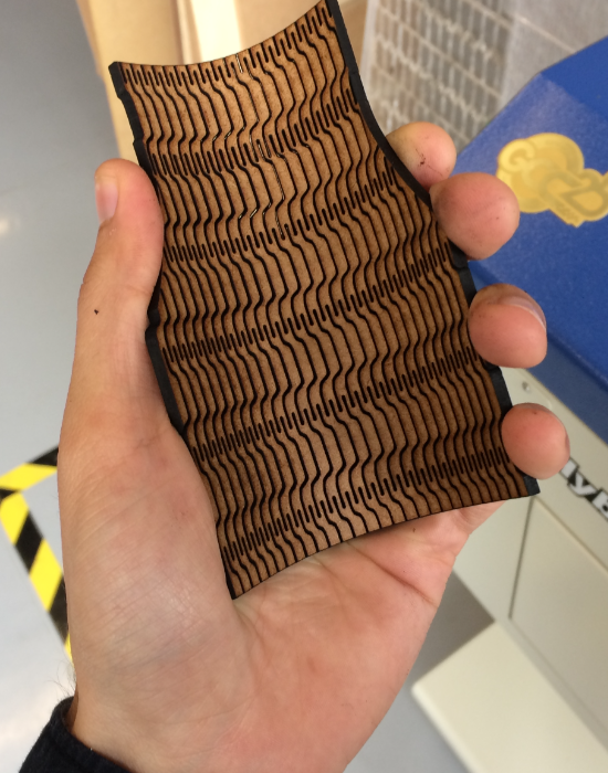
I also wanted to test some parametric kerf that gives the rigid mdf the property of bending. So I made a design with parametric bending kerf to give it a try
Fig8. - Design of a heart with parametric bending
And to try a different material (in this case 3mm plywood) I made other parametric drawings
Fig8. - Design of a heart with parametric bending
Machining
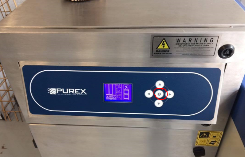
First of all we need to set up the machine. There are 2 considerations. The first one is that the machine must be powered and turned on
Fig9. - Powering the laser cutter
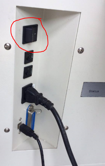
And the second one is that the gas extractor is working properly
Fig9. - powering the extractor
After the machine is up to use, we open the software for the cut. In this case we use Corel Draw. we open the software and import the .DXF files
and place them properly onto the area of work. This laser cutter have a working area of 900 mm x 600 mm. So we need to set those parameters in corel
Fig9. - placing the files inside the working area
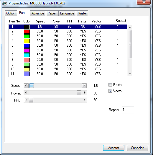
When all files are placed we set the cutting parameters. For this work, we stay with the speed of 1.5, the power of 98 and PPI of 30.
We select "vector cut" because we want to cut through the material. The "Raster" option only works for traces and usually have less power and is faster than vector
Fig10. - Cutting parameters
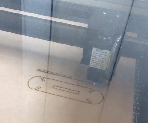
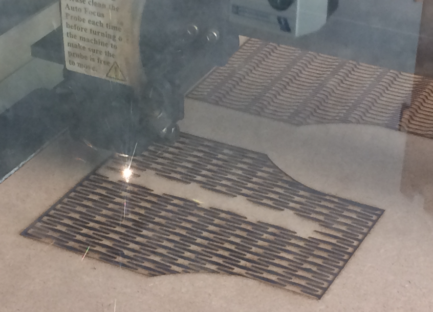
Finally, it started the cut
Fig11. - Cutting process takes place
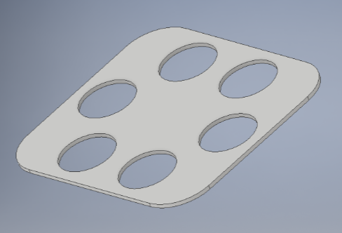
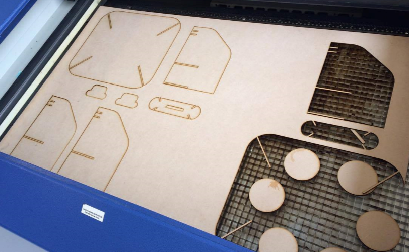
It takes around 10 minutes to complete the cut and all parts to be ready to assemble. I made the process with the 3 designs I made before
Fig12. - Successful cut of the parts
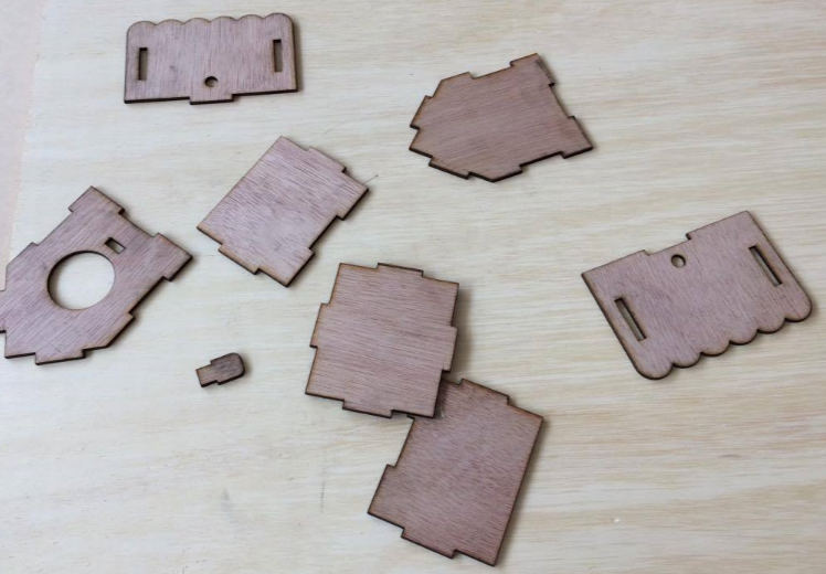
Test and Assembling
Finally, I tested if the parameters were correct. In the 3 cases it worked perfectly. All parts fit smoothly and no glue needed
Fig13. - Final designs fitting perfectly
Update
I needed more parametric kerf bending for my final project so I designed the files and laser cut them to integrate it
Fig14. - Laser cut pieces for the final project
Vynil cutting
The second part of the assignment for this week was Vynil cutting. So we needed to have a 2D design that could be
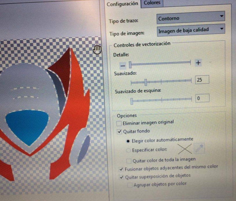
vectorized and send it to the vynil cutter. In this case we also work with Corel Draw. The big advantage is that core allows to vectorize a PNG image easily.
We were provided with red vynil, so I chose to gut Zero's helmet from Megaman
Fig15. - Image that's gonna be cut in the vynil cutter
We Proceed to set the image in corel:
Fig16. - Image imported in corel
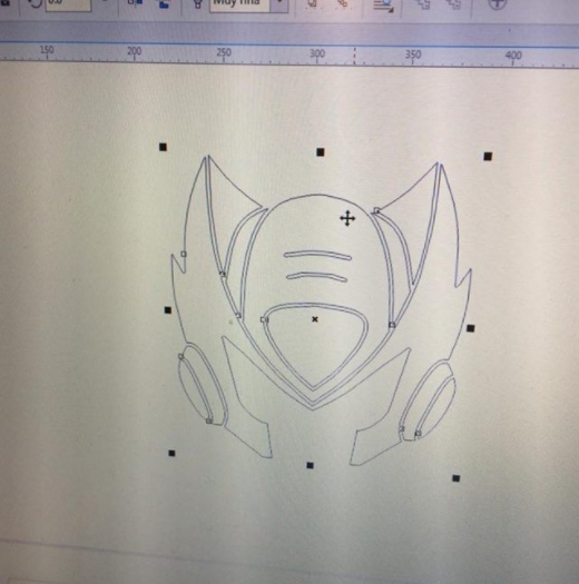
Vectorize the image
Fig17. - Vectorizing the image
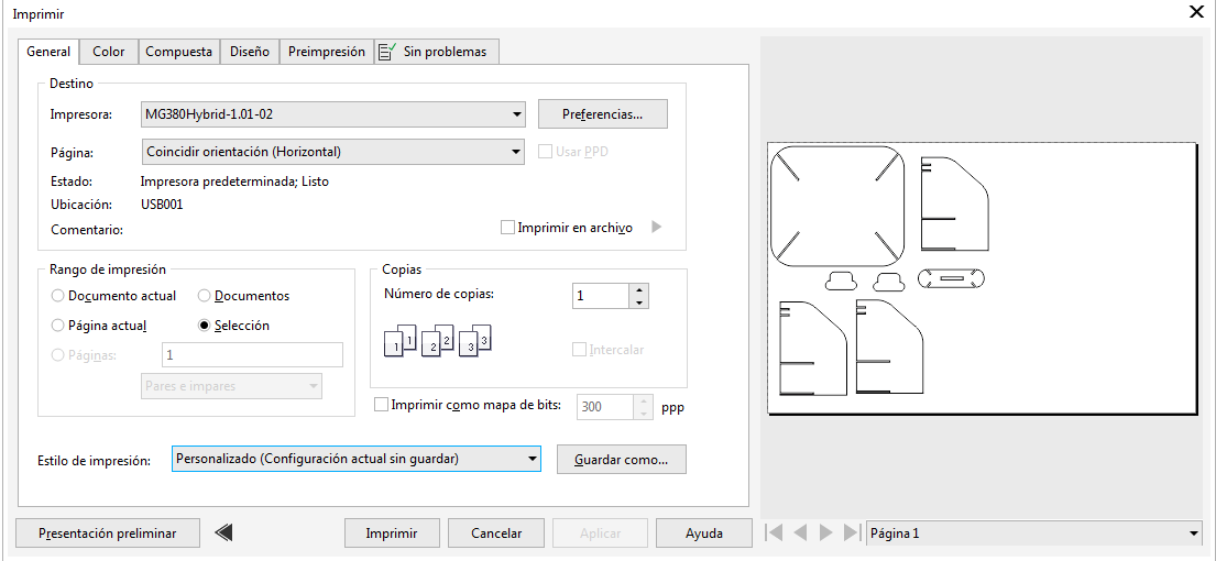
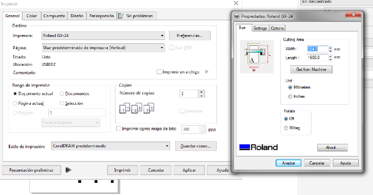
And send it to the cutter by clicking in "print" and input the following parameters
Fig17. - Vectorizing the image
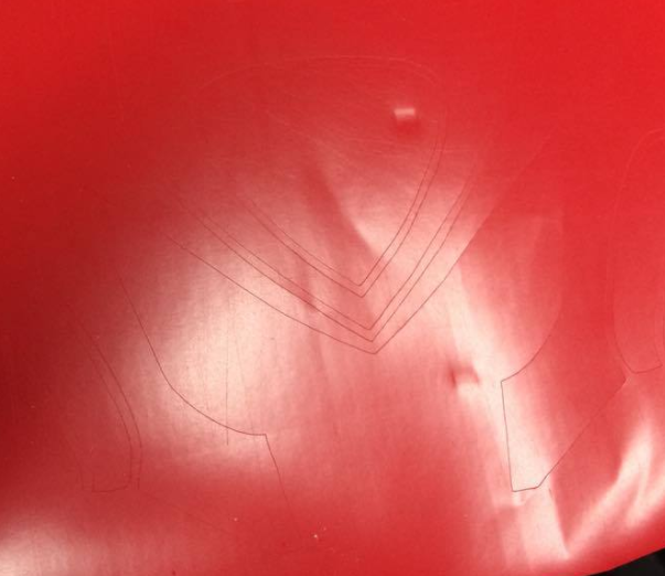
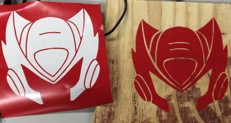
The result
Finally we obtain a cool sticker that could be placed anywhere
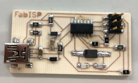
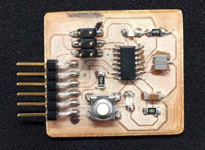
This week assignment was to make the FabISP board, an in-system programmer for AVR microcontrollers, designed for production within a FabLab that will
allow to program other microcontrollers.
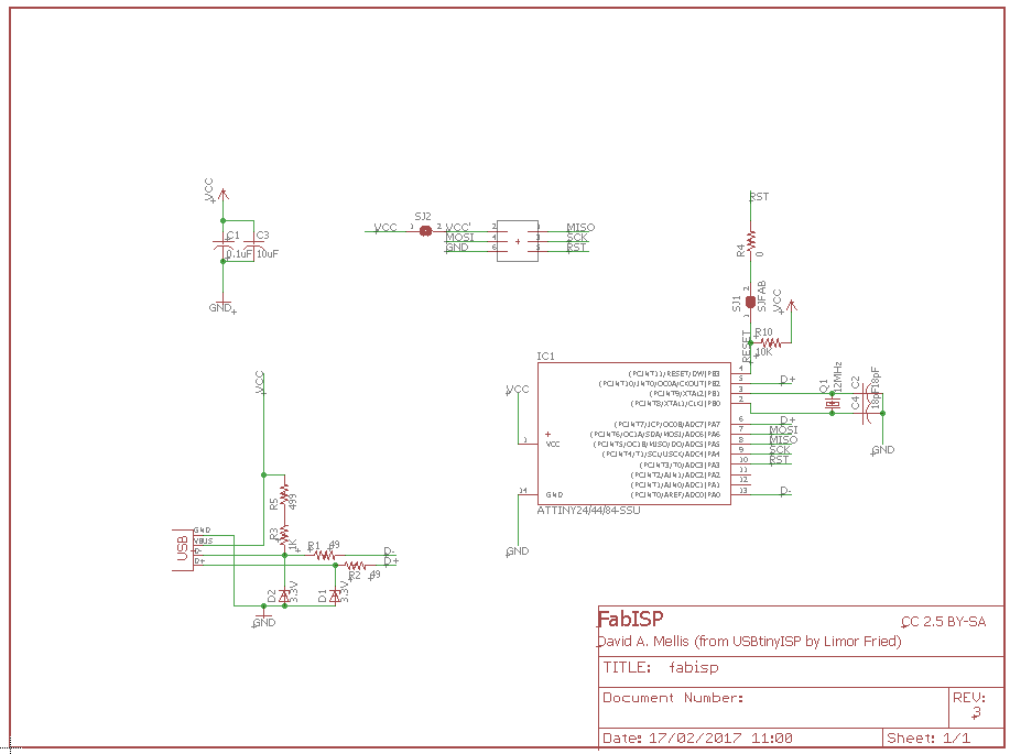
The board we decided to produce was the FAB ISP from this page. We were also given the board and schematic files
If needed
Fig1. - Board and schematic of the FAB ISP
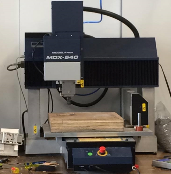
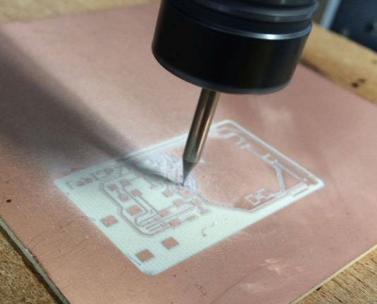
For the manufacture of the PCB here at Fab Lab UTEC we use The Roland Modella MDX-540 as the CNC router, and
"Flatcam" as the CAM processor
Fig2. - Both Roland Modela MDX-540 and Flatcam interface
CAM Processing
CAM stands for "Computer aided manufacture". It's the software that allows the comunication between the CAD design and
a machine. As mentioned, for PCB milling here we use "flatcam". A free open software downloadable Here
First of all, EAGLE allows CAM processing with the "CAM processor" button at the board and open the GERBER RS_274X that allows only surface traces
as we work with SMD components
Fig3. - EAGLE cam processor
First of all, EAGLE allows CAM processing with the "CAM processor" button at the board and open the GERBER RS_274X that allows only surface traces
as we work with SMD components
Fig3. - EAGLE cam processor
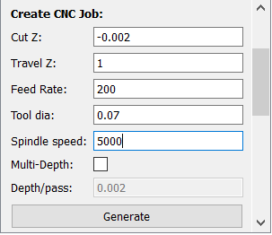
We select process job and a .gpi file will be generate, this file must be opened in flatcam in order to be processed. There, we input the parameters such as
tool diameter, spindle speed, travel z, etc that corresponds those of the Modela MDX540. I personally like working in mm so I set all parameters in mm and RPM.
Fig3. - Flatcam parameters
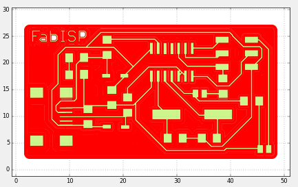
Then, select non copper region so it mills all parts that do not correspond the traces and components of the PCB.
Here the result
Fig5. - Paint region
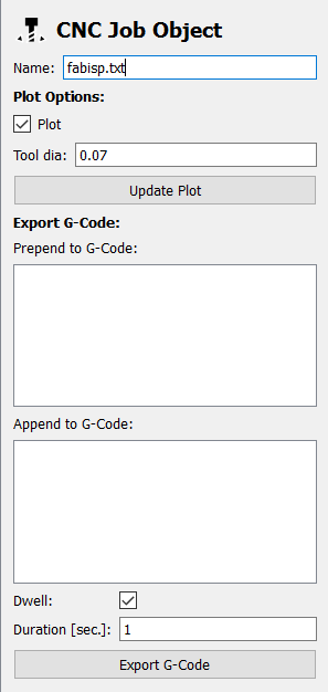
finally, we generate the Gcode file, but here's the trick. Flatcam generates a file without extension, so we need to add .txt at the end of the file name
in order for it to be a text file that contains the Gcode for the machining
Fig5. - Paint region
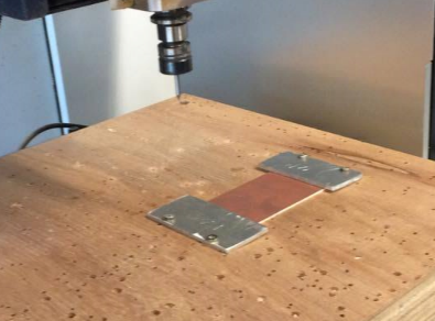
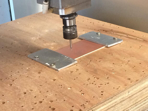
Machining
The first consideration for the machining is the setting of the origin. So to do that we must operate it manually.
First of all, the PCB material "CEM-1" must be well placed in the bed. Then the setting of the zero begins
Fig6. - Gcode file exported
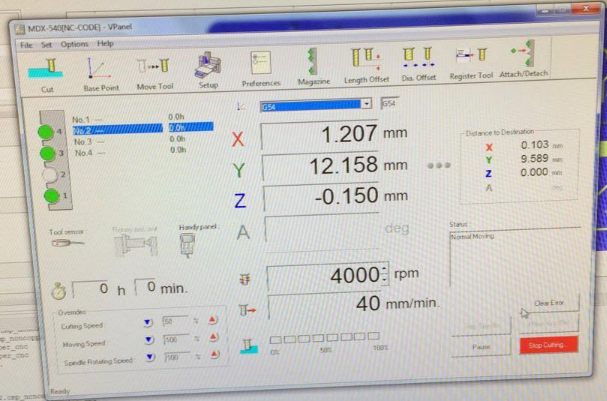
After that, we set the zero for both X and Y axis from the software of the modela
Fig7. - setting the Zero for X and Y axis
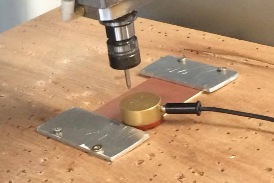
For the zeroing of the Z axis we need to place the capacitive sensor over the CEM. and press "z zeroing" in the controller
Fig7. - setting the Zero for Z axis
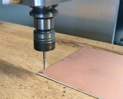
Finally, import the Gcode and Enjoy the machining
Fig8. - Machining
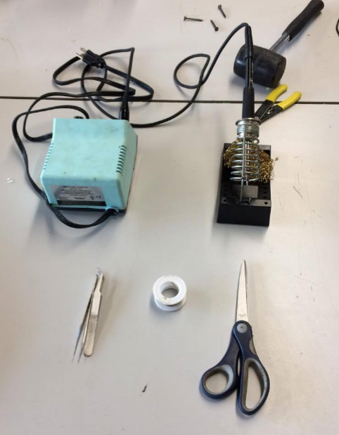
Soldering
This was the trickiest part. I had to set all materials in place before getting into the action
Fig8. - soldering station with the materials needed
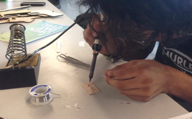
And then proceed to the soldering of the components
Fig8. - soldering of the PCB
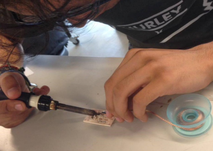
I had to de-solder some bridges that were generated for the bad soldering :/
Fig9. - de-soldering some components
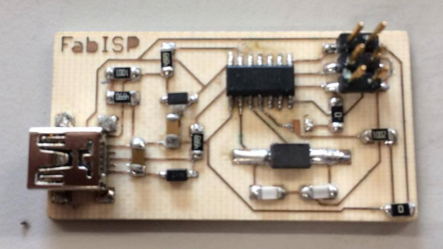
Finally. The FabISP came to life
Fig10. - ISP with all components soldered properly
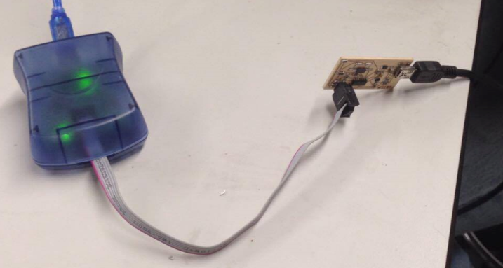
Programming
In order to program the Fab Isp, we needed an AVR programmer connected in the following way
Fig11. - Configuration of the ISP with the AVR programmer
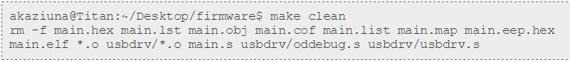
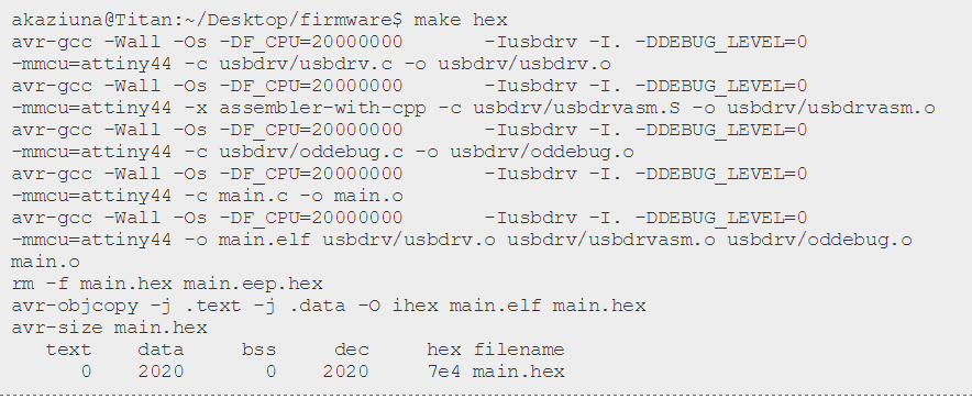
We first need to install AVRdude, then, open the terminal in ubuntu and type
You should get this response:
Type again:
you should get:
Type again:
and finally this will show of:
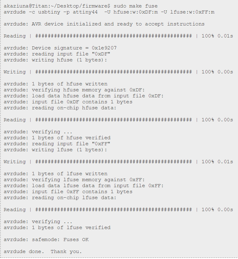
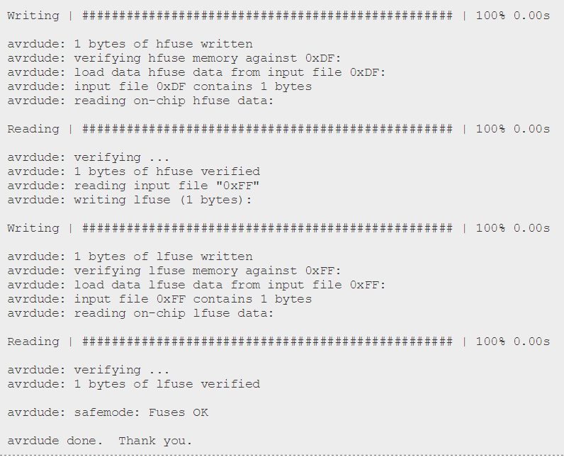
finally, type:
and finally you'll get this final response:
In order for the ISP to be a programmer and work we have to remoce the 0 ohm resistor or jumper (depending on your design) and then It's ready. My first Fab Academy PCB :)
This week of the Fab Academy focuses on additive manufacture, more specificly on 3D printing and 3D scanning technologies. We can perform various applications using
these tools combined (reverse engineering, virtual reality, 3D potography, quick prototyping among others), so. Let's get into it.
3D Printing
Most of students here at fab academy had already tested or had some experience using 3D printers. During my internships I've used the "makerbot" family of 3D printers (2X, 2 and 5th Gen), the XYZ Da Vinci 3D printer and even made my own
version of the "Prusa i3" 3D printer, an open hardware 3D printer that we see all over the internet.
I've also tested a variety of materials with the printers I mentioned before, such as the commonly used "ABS", "PLA", ninjaflex (flexible filament), carbon fiber and nylon. The results were divers. I've learnt
a lot about 3D printing materials and their behaviour.
Fig1. - Prusa i3 I've madeFig2. - Some parts printed using Ninjaflex filament
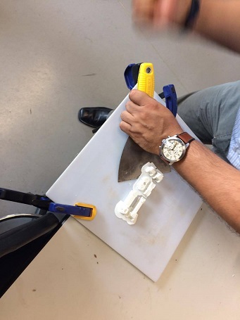
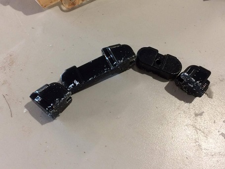
This week assignment was to 3D print something that could not be made using sustractive manufacturing (milling or turning). I've decided to print the parts I designed
on week 2 of the Fab Academy. These parts were kinda complex in design (are shapeless amorphous form) that simulates the phalanx of the fingers and their joints, combined with
some wholes through which will pass a rubber band and a nylon chord. And the plus is I'll get closer to my final project already having my parts.
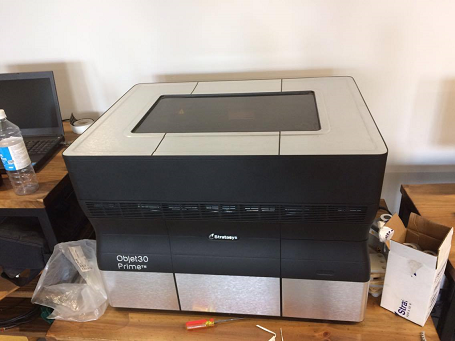
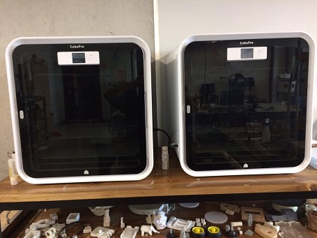
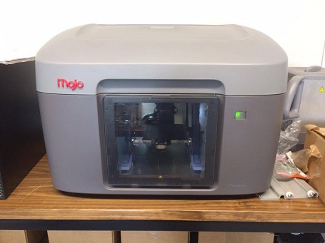
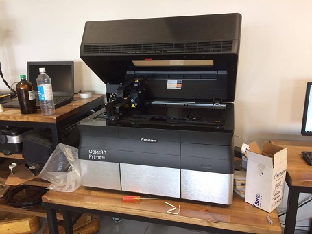
We currently have 3 models of 3D printers here at Fab Lab UTEC: Two CubrePro from 3D systems. 2 Object Prime printer from Stratasys and a Mojo 3D printer which look like this:
Fig3. - From top to bottom: Object prime 3D printer, CubePro 3D printer and Mojo 3D printer.
The first printer I used was the CubePro, so I had to download the software that generates the code for this printer (the printer won't recognize .stl format) from 3Dsystems page
The desktop app should look like this:
Fig4. - My 3D printing softwares.
Double click in it and we have the CubePro interfave which shows the workspace of the machine as most dedicated 3D printing softwares:
Fig5. - CubePro Software Interface.Fig6. - Workspace (platform) of the CubePro as shown from the software
The first thing to do is import the .STL file generated previously from the CAD software using the "open model" icon. I used Inventor for almost all my designs so I already had my files ready
Fig6. - STL files
The screen will show us the 3D view of the STL file which we can place wherever we want inside the platform and modify the parameters for the print. After some few adjustments, the model was ready to be printed:
Fig7. - Rearanged to be ready to print
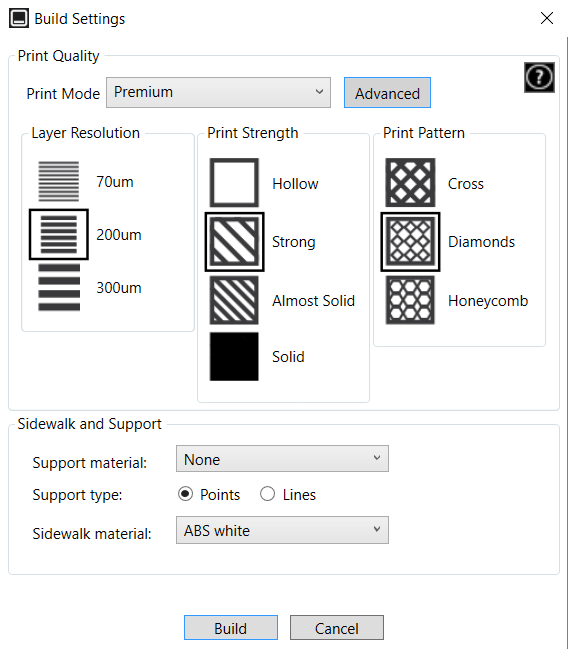
In order to generate the code for the CubePro we need to use the "build" tool. After we click there we must input the parameters we want to set the quality of the printing. Usually there are 3 default settings which are "low qualiy", "standard" and "high quality":
Fig8. - Default settings
We wanted a fast but decent quality printing, so we selected the "Standard" settings and generated the CubePro file that the CubePro could read.
It's worth to say that we need supports for this print. We do this by selecting the material for the support from the settings. In this case it's ABS. Finally we get the Estimated build
time and the amount of material that it'll use for the build (in grams)
Fig9. - Support and Estimated time of the printing
The format generated is .CUBEPRO, that can only be read by the CubePro 3D printer.We save the file in a USB and move to the printer !
We instert the USB in the USB port of the printer and it will show our file in the display. Our file was named "readytoprint"
Fig10. - CubePro Display
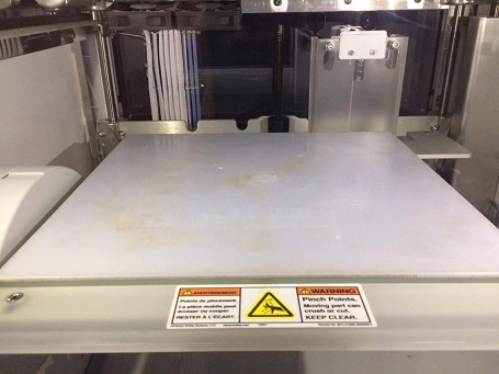
Before we start the printing we need to do some previous settings to the printer. First of all,
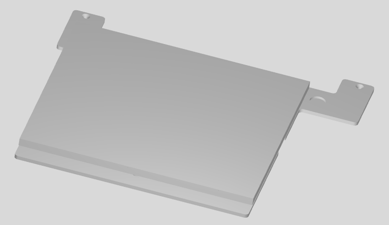
we need to make sure that the platform is in it's place. The first time I send my files to be printed the
platform was missing and it started printing in the air. I had to cancel the print and put on the platform.
Fig11. - Plataform set in place
The CubePro platform does not provide any adhesive material by itself (it does not heat the bed nor hace blue tape). So, in order for the material
to stick into the platform we need to cover it with liquid glue in the area of the printing
Fig12. - Covering the CubePro platform with glue
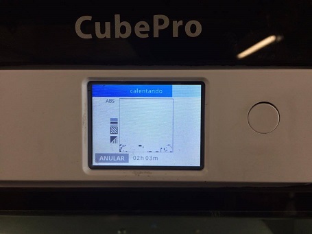
We press the tactile button from the display and the printer will start processing the job. It might take several minutes depending on the complexity
of the design. Affortunately it took only a few seconds. Then it will put in place the platform and heat the nozzle to, finally, start printing our pieces
Fig13. - Processing the fileFig14. - Heating nozzle
This printer uses ABS as mentioned for both the printing itself and the support
Fig15. - CubePro Printing the files
And after more or less 2 hours of printing, the pieces were ready. To retire them we retire the platform from the CubePro and, with a scraper tool,
we take off the pieces and retire their supports manualy
Fig16. - Retiring the printing from the baseFig17. - Just finished printing pieces
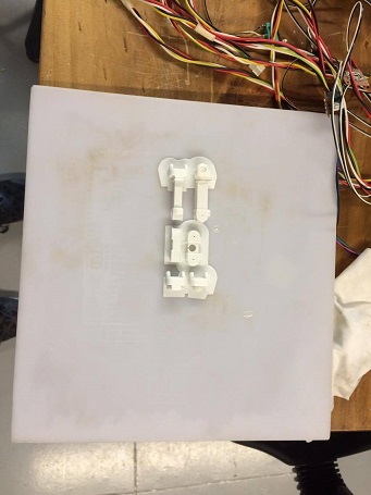
I already know how 3D printing with this technology worked, so I was curious about how the other 2 models of 3D printers would perform. I sent the same files to the
object pro 3D printer from stratasys and designed a smaller but more complex design (wich contains a coil) for the Mojo.
These two printers were a bit slower than the CubePro, but more precise, the finishes and the quality of the printing were way superior than the ones from the CubePro even tho they also
worked with ABS
The Object Prime had a peculiar way of working. The material for the parts is also ABS, but the support material is wax. So it had also a peculiar way of handling and setting the parameters.
The workflow is similar from the CubePro or other conventional 3D printers (the nozzle heats up and deposes material alongside the base my layers). It has two nozzles, one for the support and the other
for the objects itself
Fig18. - Object printingFig18. - Setting up of the Object Prime 3D printer
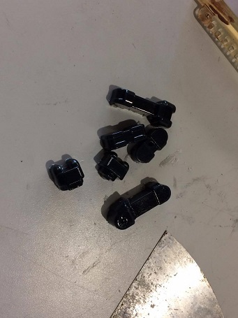
It took more than 2:30 hours to complete the printing. Then we finally got to remove the pieces from the printer.
Here's the reslut:
Fig19. - 3D pieces printed in the Object Prime
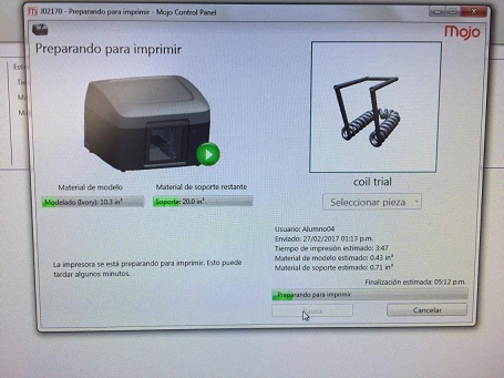
For the Mojo 3D printer, not a lot of filament was left. So I designed a small coil part for the final projet of Alexandra Roldan Fab Academy. Go have a look
at her page. She didn't had previous experience using Inventor, so I 3D modeled her part and printed it in the Mojo.
Fig20. - Test part for the Mojo using Inventor
It recognizes STL file and prints directly, so the set up was easier
Fig20. - STL setup using the makerbot software
We saved the file in a USB and started setting the parameters for the Mojo print
Fig21. - Set up using the mojo software
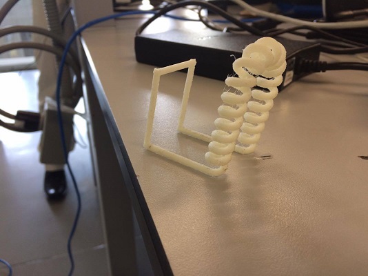
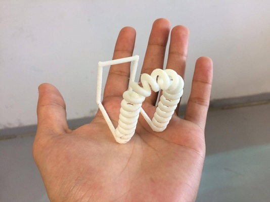
The printing lasted 3 hours, the support material that the Mojo uses is PVA (a soluble polymer which is retired by a mixture
of water and a solute), and the material for the print itself is ABS. It took about 12 hours to solve the support, but finally,
the piece was made:
Fig22. - 3D printed piece using the Mojo
3D Scanning
For the scanning, I used The Kinect for xbox 360 that were provided by the lab
Fig22. - Kinect for Xbox 360
As software I used the trial version of Artec Studio.
Fig22. - Artec studio shortcut
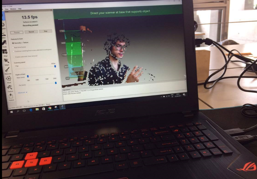
Then proceed to the scan
Fig22. - Artec interface for scanning
I couldn't do the scan by myself because It was meant to be a 360 scan from the same distance and the scanned
object (me) had to be static. So I asked some of the undergraduate students to be the models
Fig22. - Artec interface for scanning
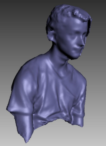
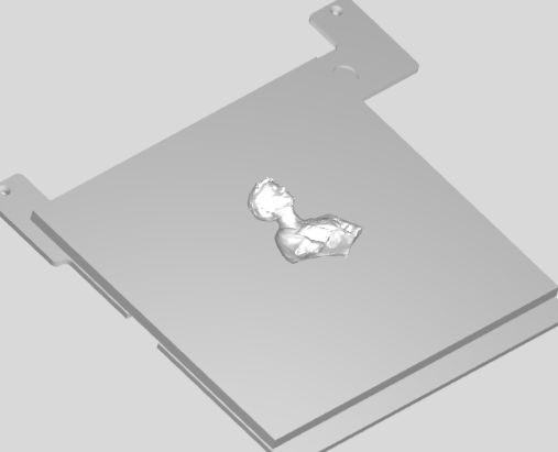
It wasn't perfect, but it was a scan after all. The result:
Fig22. - Artec interface of the scanning
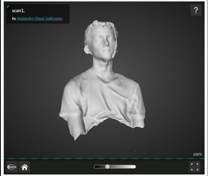
Artec trial didn't allow the saving of the files, so I needed to export via viewshape. A .PLY file generated
Fig22. - Scan in viewshape
In order to print the scan, I used REALconverter to convert the PLY file to STL file
Fig22. - Convert PLY to STL
And It was ready to be printed in the cubepro ! :D
Fig22. - STL file
Week 6: Electronics Design
So, this week was about electonics... But, in order to understand this complex world of components, schematics and symbols we must review the basics.
This week assignment was to redesign the "Hello World Board" (Link here) And add
an extra LED and a button. So in order to complete it we must get familiar with the basic electronic components such as LEDs, capacitors, resistors, among others, with their respective symbols
, Schematic design and the routing of the board. Some CAM knowledge is expected since the board will be made exactly as the ISP from week 4: Electronics Production. So, let's get into it !
Fig1. - Echo Hello Worl Board From the Fab Academy Archive
We get a "master class" of electronic components from a member of the Fab Lab UTEC: "Leidy", who taught us the basic principles and symbols of the electronic components. Following by the "making of" the Hello World Board and how to add the required components
on the schematic (for the beginners)
I already had some knowledge about electronics and the making of PCBs from my internship. I had the tasks of making some PCBs for the university projects so I already knew how I'd complete the assigment.
As a student, I got a 3 years licence from Autodesk softwares. I had already installed EAGLE from Autodesk and that was my choice for all the electronics production during the Fab Academy
Fig2. - Eagle Shortcut on my Desktop
Before I started the schematic. I had to download a couple of libraries for certain components. The first one was the fab library (Link here)
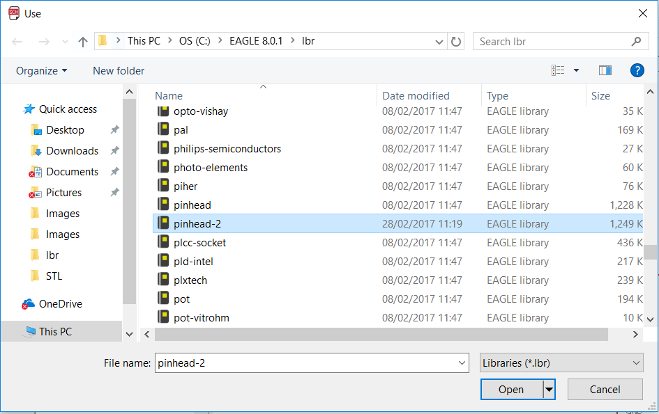
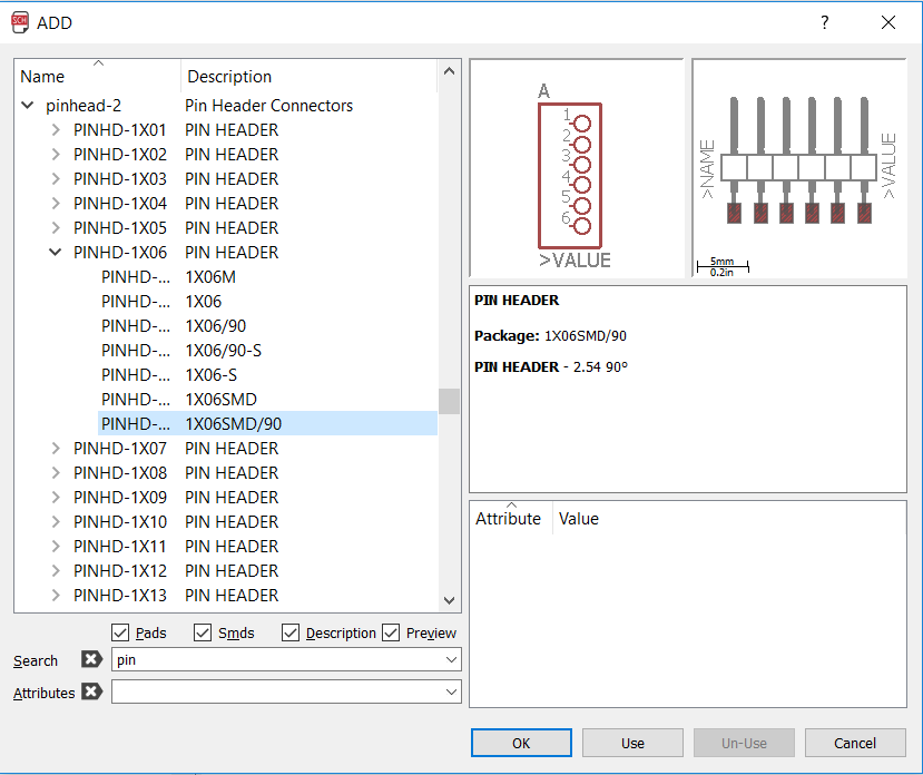
And a pinhead library called pinhead-2 from the web for the 6 pinhead smd FTDI communication. All libraries must have been located in the library folder in the EAGLE folder:
Fig3. - Both fab and pinhead libraries on the Libraries folder
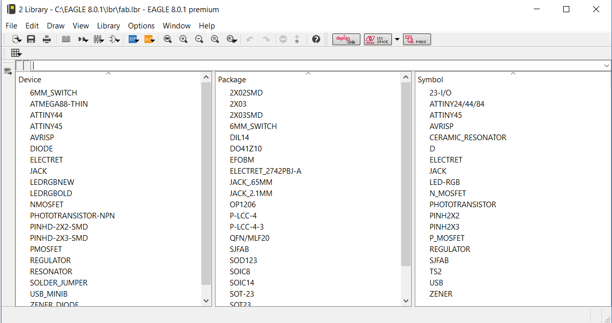
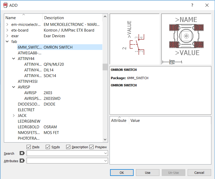
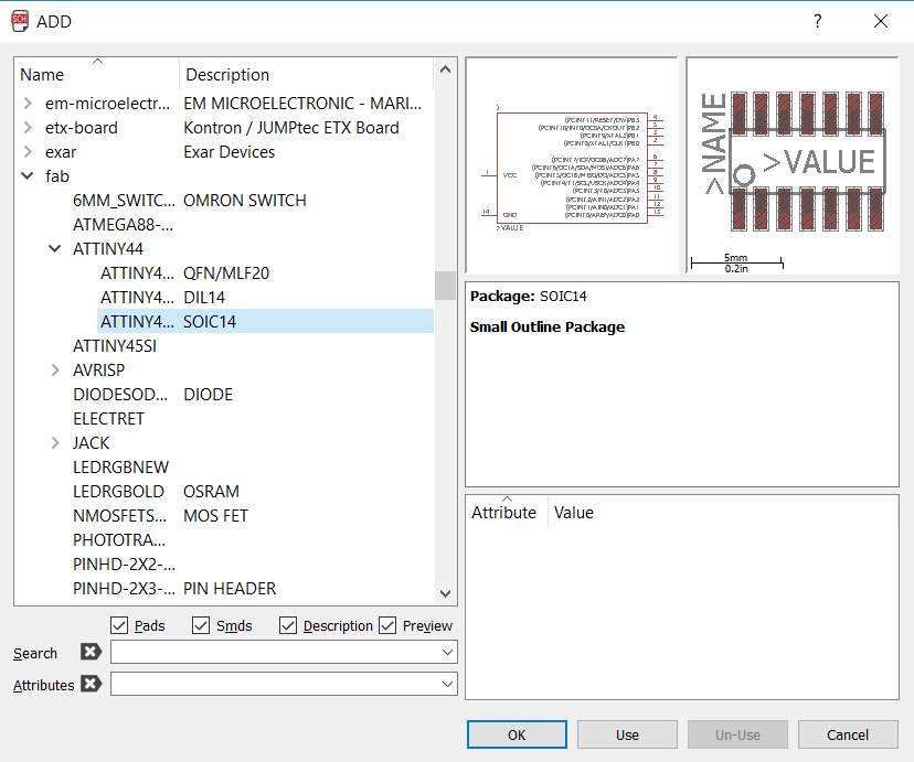
The fab library contains most components for this and future assigments of the academy:
Fig4. - Components found in the fab library
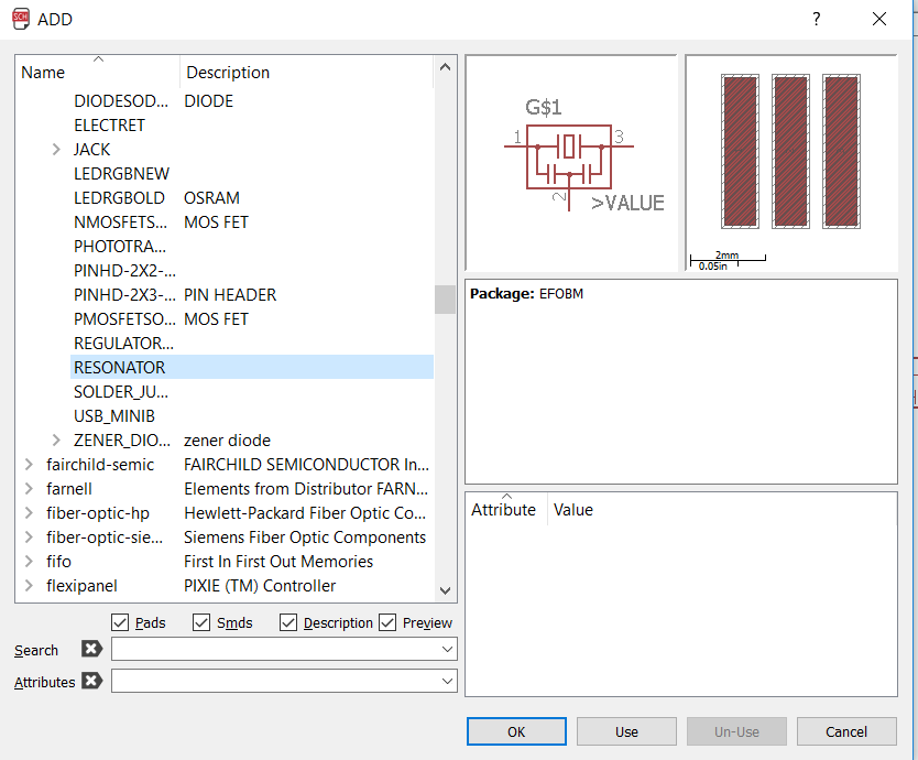
I started setting all componets inside the schematic sheet.
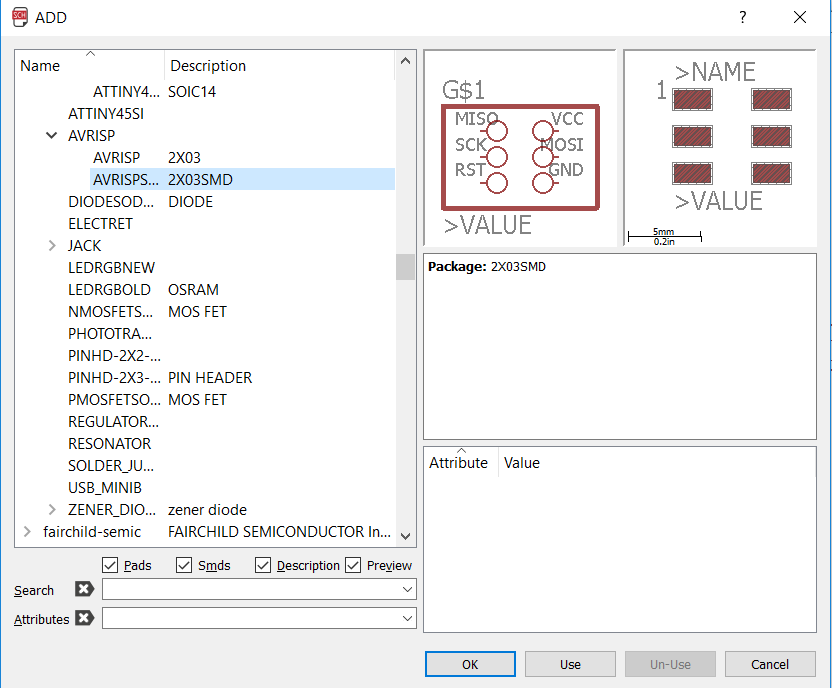
The 20 MHz resonator, the attiny44b, the push button and the AVRISP were easily found in the fab library:
Fig5. - Resonator, attiny44b, push button and AVRISP inside the fab folderFig6. - set in place
Then, I put the 6x1 smd pinhead for the FTDI communication found at the pinhead-2 library I downloaded
previously
Fig7. - 6x1 pinhead
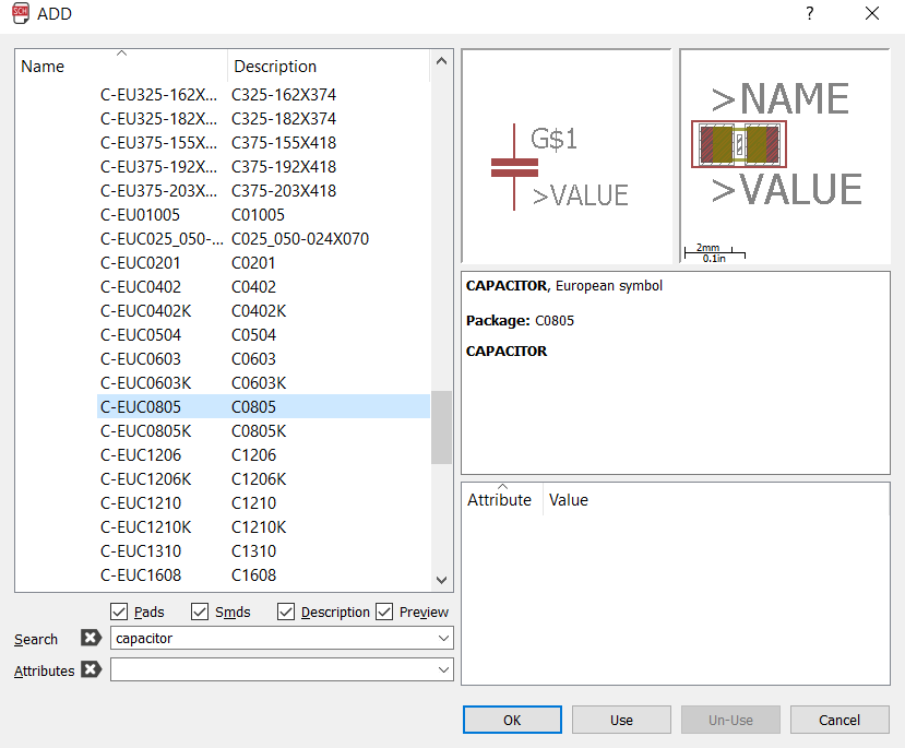
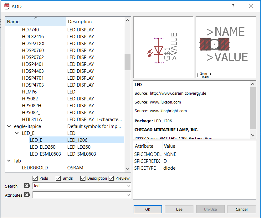
Then I followed up with the other components (resistor, capactor, LED)
Fig8. - SMD resistorFig9. - SMD capacitorFig10. - SMD led
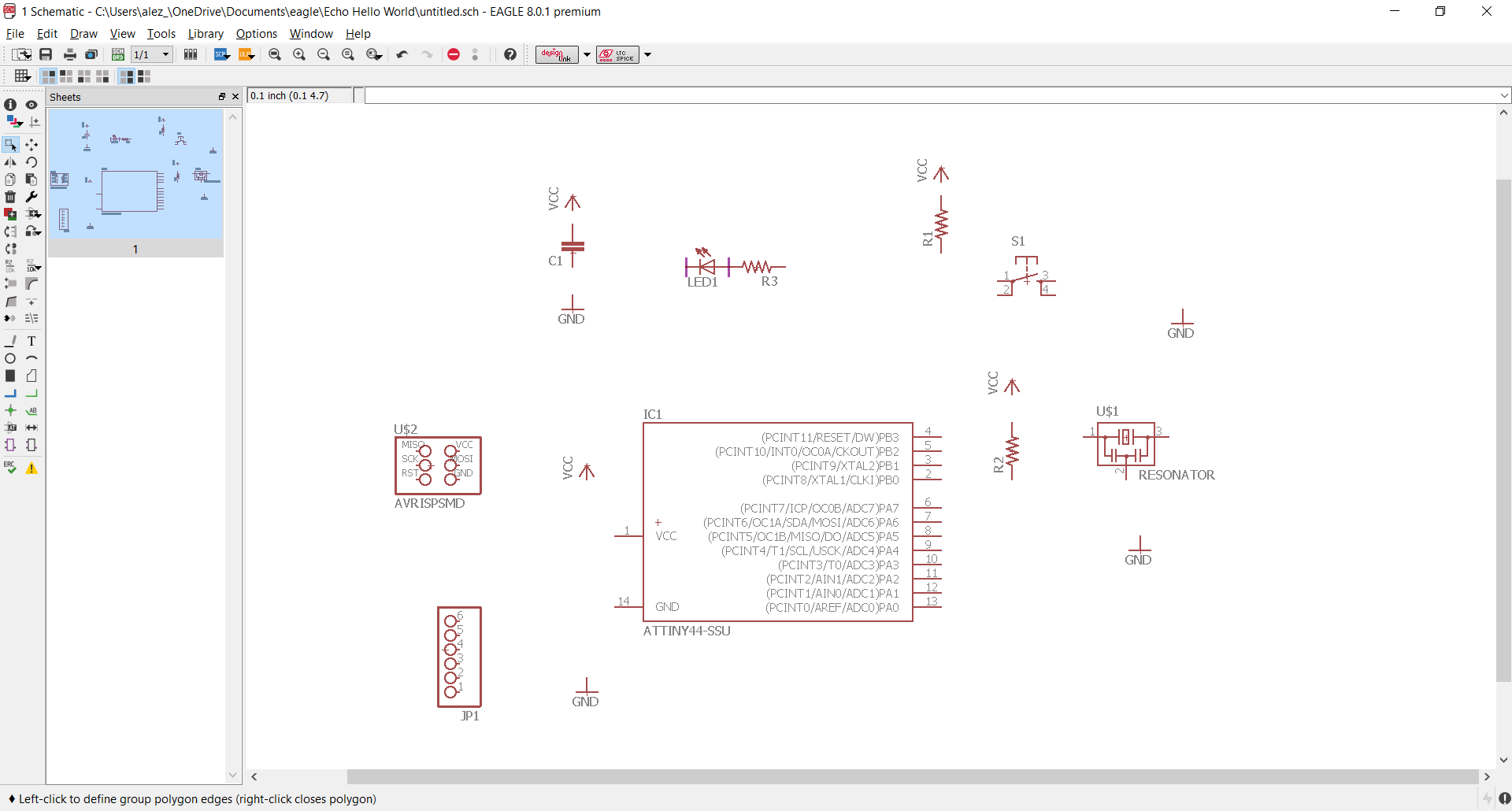
All components were set in place
Fig10. - SMD led
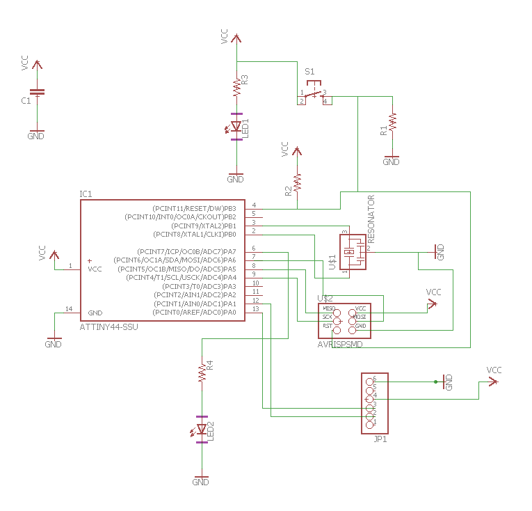
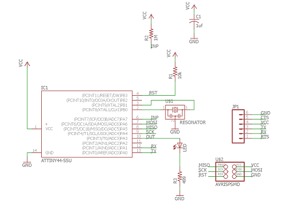
And I proceded with the mating of the components. After a couple of tries, finally
completed the schematic:
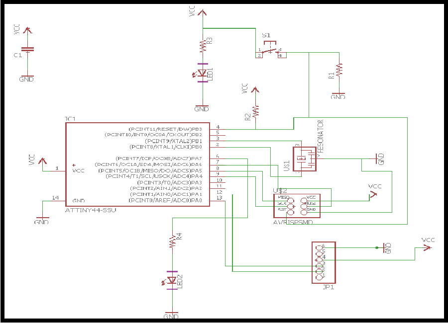
Fig11. - Schematic
EAGLE lets you switch from the schematic to the board for the routing. It takes the physical form of the components
and lets you arrange them as you wish in order to perform an exact sketch of your PCB.
After arranging the components, I used the autoroute tool. It helped me a lot in the design of the PCB.
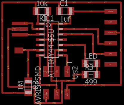
After a couple of tries, here's the final board of my "Echo Hello World Board"
Fig12. - Board
Fabrication
The fabrication process takes place. WE use the Roland Modella MDx 540 for the machining and Flatcam (a free software you can download from the web)
as the CAM Software.
We followed the following workflow: After routing the Board in the EAGLE, we press "cam processor" as in week 4. This will generate the file that will be read
by our cam software (Flatcam in this case).
Fig13. - CAM processor in EAGLE
Then, as we work only with SMD components, open the GERBER RS_274X job that allows only surface traces. No
mirror is needed
Fig14. - Workflow for cam processing
Then, we process the job and a .GPI file will be generated in the path you selected before. Then it's time to move
to the CAM software. Open the file you generated before. you should be able to see the traces of the components:
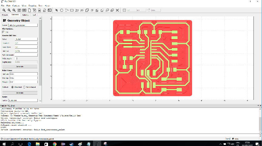
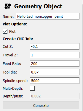
Fig15. - Flatcam interface
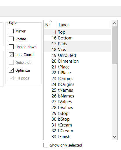
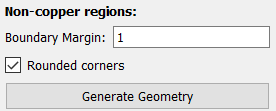
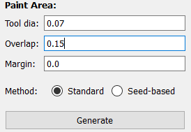
I like the finish when all the non copper region is retired, so we give a margin region of 1 mm offset and give the tooling
parameters: 0.07 mm tool diam. Click in the region we want to mill and the path will be generated automatically
Fig16. - Flatcam parameters
And finally, the cutting parameters. Then we export the file with the extension .txt
Fig17. - Generating Gcode for the milling
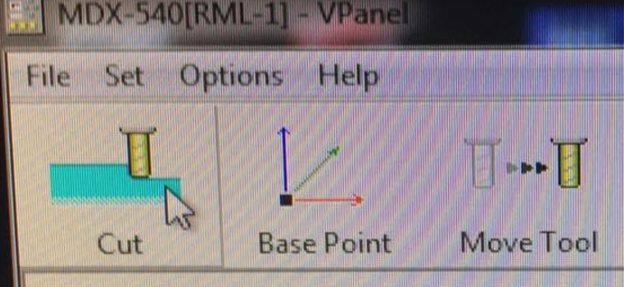
Once we have the Gcode file, we move to the modela. We open the software called Vpanel and import the gcode
Fig17. - Gcode ready in vpanel
We set all the zeros for the 3 axis as we did previously on week 4 and Start the milling by pressing CUT
Fig17. - Senting the Gcode and start the milling
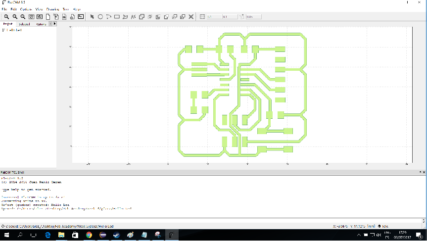
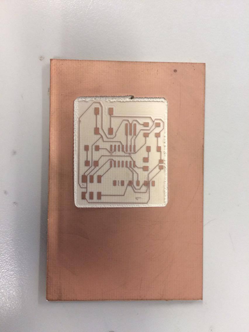
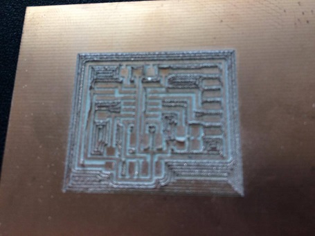
Here's the result:
Fig12. - Final board
What went right and wrong
All the non copper region was milled correctly with no traces missing.
Failed the clearance of the tool as I set a z cut of 0.1 mm and the material is a little bit thicker so it needed
to be cut manually. I'll set a deeper z cut for the boards for the next PCB makings !
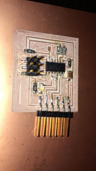
Soldering and putting it all in place
I followed the same method for the soldering. First we put some solder on one pinhead of heach component. then put the component on as I heat the solder and fix the
part exactly in position. Then complete the soldering of the component. The soldering took me about an hour to complete, but all the effort had come handy as I succesfully
completed my "Echo Hello World Board"
This week assignment was to use a cnc machine such as a milling machine to make "something big"
such as furniture, big figures or some other press-fit ideas.
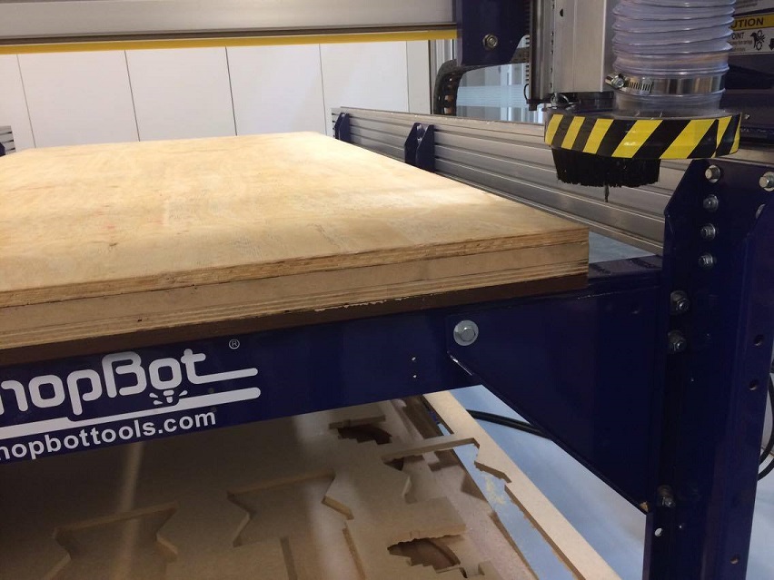
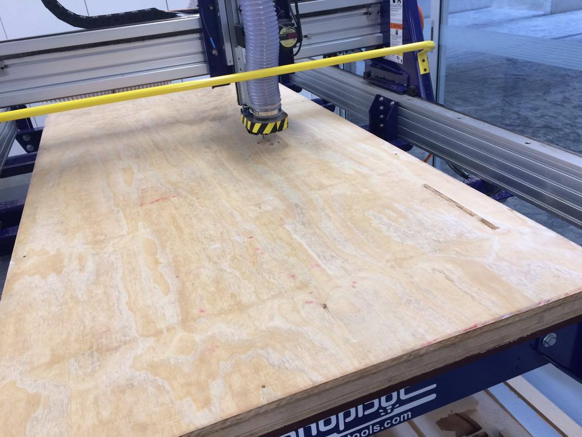
At Fab lab UTEC, we have 2 "Shopbot" milling machines. One which has a working area of 2440 x 1220 mm (24'' x 48'') and a smaller one
which has a work area of 1220 x 1220 mm (24'' x 24''). The material we used was plywood. We were provided with a full wooden board of plywood and
we were allowed to choose the thickness of it (the boards came with 18, 16, 14 or 12 mm of thickness). I chose the 18mm thick board.
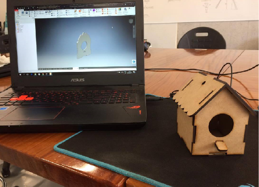
Fig1. - Shopbot milling machine
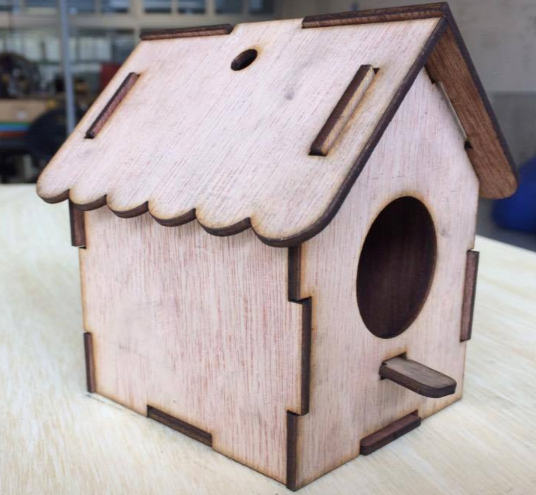
I struggled a little bit in deciding what "big thing" I'd made. I wanted it to be useful, so I started to think what would it come really handy for me.
my sister just brought a puppy at home so I decided to make her (penny, the dog) a house so she can carry anywhere she wants.
I started with the design. It was also kinda tricky to design a full functional esthetic dog house, but after looking some designs from the internet, I finally came
with the idea
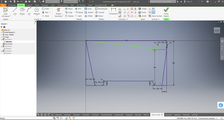
For this, I used (as usually) The Autodesk Inventor software. I started designing the side walls of the house. I didn't want it to be too small,
so I was generous about the dimensions of it
Fig1. - Shopbot milling machine
I gave it a thickness of 18mm in order to represent how the piece would look
Fig2. - Design of the raw side walls
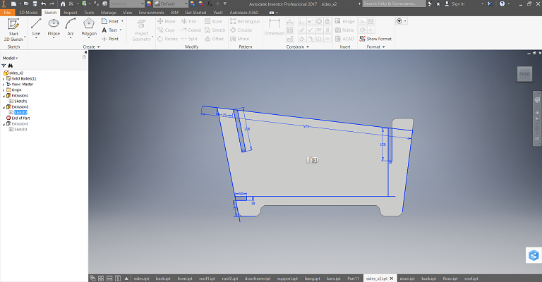
Then I made the inserts for it to be pressfit
Fig3. - Designing the inserts
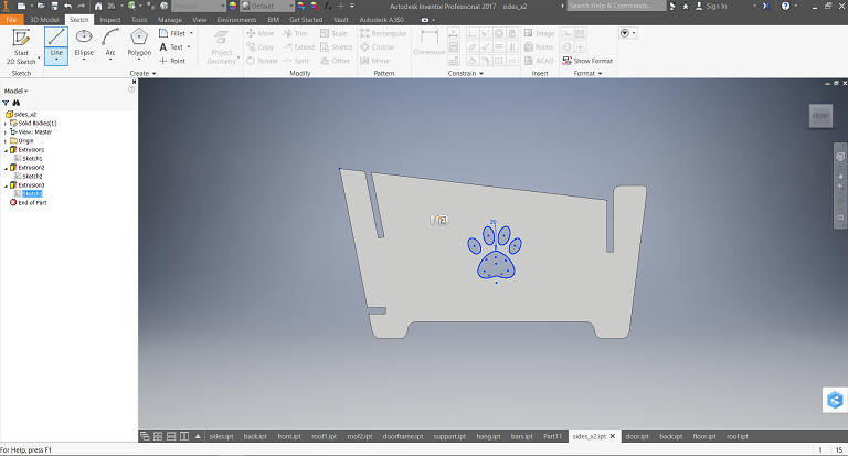
And I gave it a personal finish :)
Fig4. - Design of the full side wall with the finish
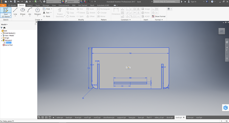
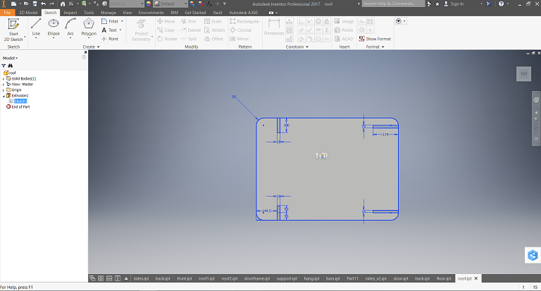
That was the workflow of the next parts. The house had in total 6 parts: 2 side walls, the front door, the back wall, the roof
and the floor:
Fig5. - Design of the door Fig6. - Design of the back wall Fig7. - Design of the floor Fig8. - Design of the roof
Having designed all the needed parts, I proceeded with the machining. We used "vcarve" as the CAM software, and the proper
Shopbot software for the zeroing and sending the job.
I exported each side of the ipt part as a .dxf file so the vcarve can read them as vectors. I imported all .dxf files
to the vcarve document and arranged them in order to fit all parts in one board.
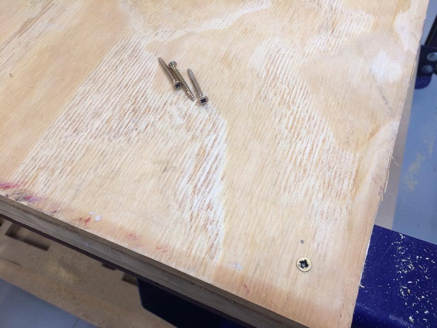
Once I had all the parts set in place, I proceded to put some holes in places where the endmill won't be going through, so I can
screw properly the boart into the sacrifice bed (so the board doesn't move during the machining and to loose all bendings).
All the parts where in place, so I started to set the parameters of the machining. For this I separated the machining in 2 different jobs:
The first one was the "drilling" of the holes for the screws. and the second part the milling itself.
For the little holes, I set a depth of 9mm (not too much so it can only be a reference of where to screw) and the proper endmill,
as stated in class, was the up-cut endmill (so the chip will come upwards)
It's worth saying that I added the "fillet" for the sharp edges so I get actual sharp edges ando not smooth curved ones
Fig9. - Chosing the proper endmill
For the milling itself, two different jobs were needed (but put together to be machined at the same time): One for the outer layer (the one that actually
cuts the pieces), and the insides of the pieces where the finishes were located.
For the outer layer, the tool was a downcut endmill, and had to set the machining to be external (so the piece gets its actual size) The RPM were set to 1400 rpm
and gave a depth of 19mm deep (so we assure the piece gets cut. It's ok if the bed gets milled in the process)
Tabs were added so that when finishing cutting a piece it stays in place.
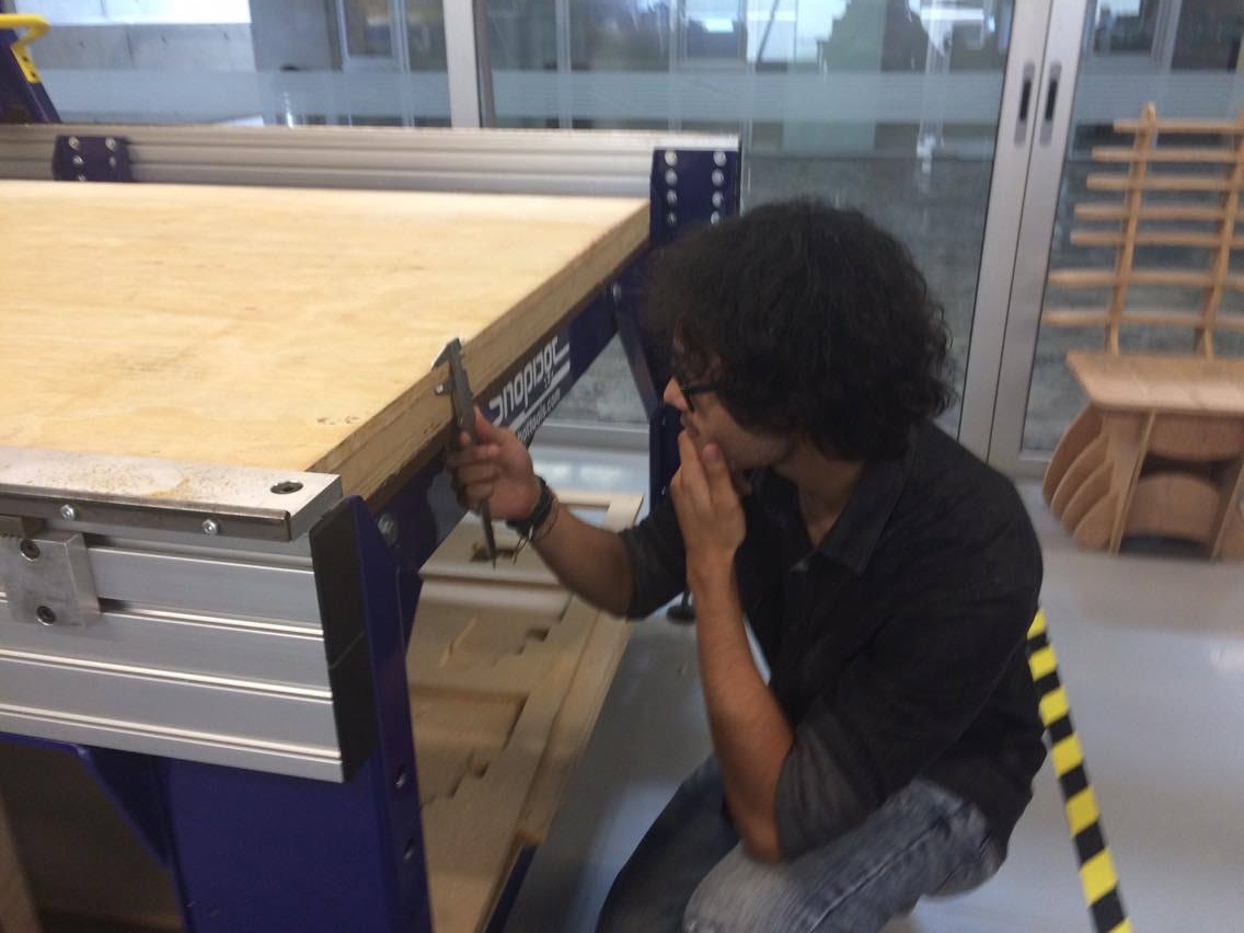
It was the moment to finally use the machine. The first thing to do is to fill with the "stock" (the raw material that will be machined). So, the first
thing I did was to verify its thickness (we want all the pieces to fit well and without effort, remember).
Fig10. - Checking the thickness of the material Fig11. - Thickness of the material
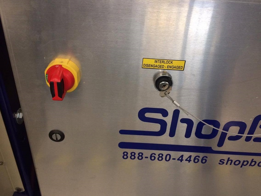
Once the material is loaded, we procede to do the initial settings of the machine such as
zeroing, setting the RPM of the spindle, turning on the vacuum and turning the spindle key. We used the
Shopbot software for these purposes
First of all we need to make sure to turn on the machine and turn on the spindle key in order to comunicate the software with the machine itself:
Fig12. - Turn on the machine
Then, we open the Shopbot software and select the remote control icon. It opens a cursor controller so we can move the x and y axis of the shopbot
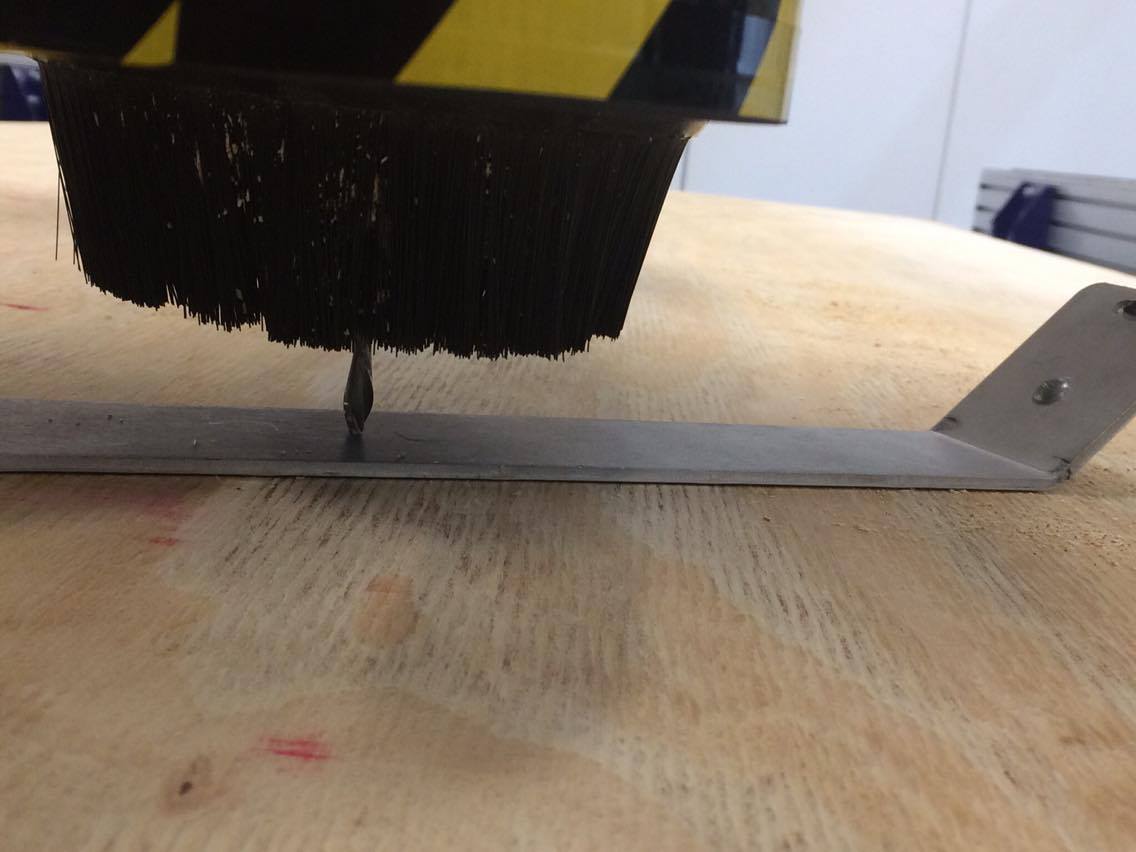
When we think we were over an accesible and flat enough area, we set the zero of the z axis (the top border of the board) for that we use an
alluminum plate located near the spindle and put it just behind the endmill. The plate is used so the bed doesn't plung and alter the z axis and, therefore, all the machining.
then we push the z axis button of the controller and the endmill starts tracking the top of the plywood (or the alluminum plate in this case) in order to set the
zero of the z axis:
Fig13. - zeroing of the z axis
Now we select the autozero button in the controller. The machine will automatically calculate the zero for both the x and y axis which
will be located just above one of the corners of the board
Fig14. - zeroing of the x and y axis
We'll get the following message
Fig14. - Message showing the zeroing
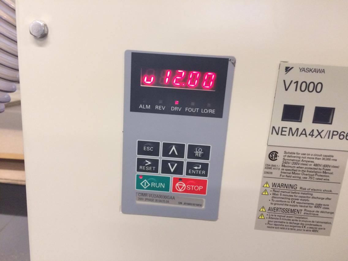
We the display by default shows that the spindle will have a 12000 RPM speed, so we need to set it to 14000. For that we select the RPM
option from the controller and set to 14000 RPM
Fig15. - machine set at 12000Fig15. - Changing the settings from the softwareFig16. - Machine changet its settings to 14000 rpm
The machine is ready to work !
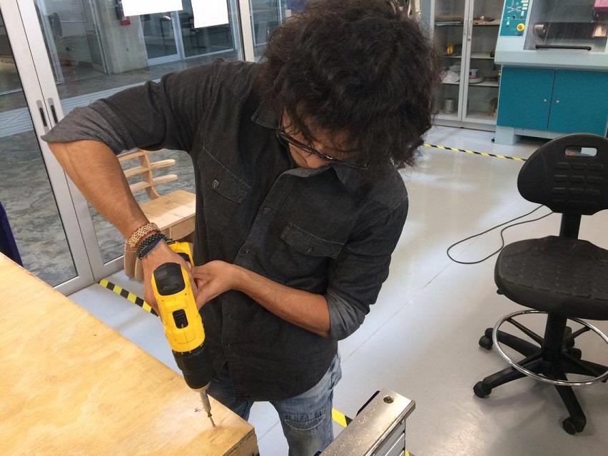
I sent the drilling job first, in order to have the physical reference of where to put the screws. The machine started drilling
the board just in the right spots
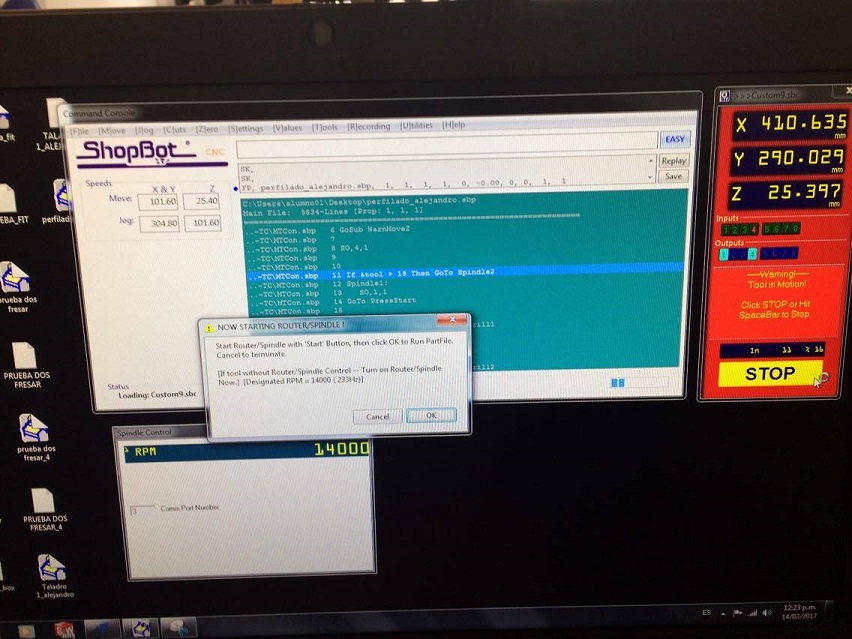
A few seconds after we sent the job to the shopbot, the screen showed a warning message that indicates that we must start on the routing/spindle.
for that, we have a selector with two buttons, one for starting the spindle and other one for the reset; when we get that message we must press the green
"start" button. The spindle will start turning at 14000 RPM. Then we press OK
Fig17. - warning message from the shopbot Fig18. - Starting the spindle
The drilling job started !
Fig19. - drilling of the board
Once the job was completed, I set the endmill position far from the working area and proceded to put the screws through the bed
Fig20. - Screwing the board Fig21. - board screwed tight
Finally, we get into the milling itself ! This operation was similar to the drilling. The "start routing/spinle" message was also shown.
We knew what to do. I pressed the green button and clicked OK. The milling operation Started !
Fig22. - Milling operation after a few seconds from the start Fig23. - Close up of the endmill
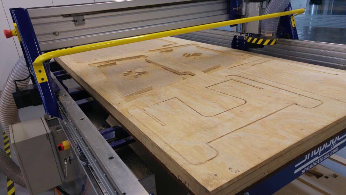
All parts had been milled perfectly.
Fig24. - Milling operation finished
And I proceded to take off all the parts from the machine and unscrew the remains.
Fig25. - Taking off the pieces
Finally I assembled all the parts. After all the machining, I found out that one insert didn't quite match
in it's respective place because of a slightly inclination of it (I didn't consider the angle of inclination when designing the parts... what a fool).
But I corrected it quickly with a rasper (yes, I had to rasp an angle of inclination into an insert so it'd fit smoothly.)
The assembly was done and I got a nice, cute, useful and portable dog house for my puppy pet !
This week assignment was to program the hello world PCB that I designed in week 5 "Electronic design". So I followed the tutorial
In this page. It describes step by step how to program the Hello world
using the arduino IDE, the most common programming IDE nowadays and easy to learn
The first thing to do is download the Arduino IDE. It's free at the official Arduino page.
Then, we proceed to read the Microcontroller Datasheet that I used for the hello world, the Attiny 44
Fig1. - attiny44 pinout
The numeration of the pinout is different from the numerations of the programmed pins in the arduino IDE.
This table shows the equivalency between the attiny44 pinout and the arduino IDE pinout for programming:
Fig2. - Pinout equivalation table
The most relevant part of the datasheet I could get is that, even through It allows TWI or
I2C communication. It doesn’t have serial communication by itself as it must have a programmer
such as the ISP we made to allow communication with the port. Here's a link to the microcontroller datasheet:
Attiny44 datasheet
That's the basic we need to know about the microcontroller to program it. Next step is to download the attiny extensions for the Arduino.
they all can be found In this zip file.
Restart the arduino IDE, You should be able to select the attiny family microcontrollers at the board menu as well as the
frequency of the crystal you use
Fig3. - Arduino IDE with the attiny family microcontrollers
Enough with the software. Let's move to the hardware and connections.
In order to program your attiny microcontroller using the arduino IDE you need to do something that's called "Burning The Bootloader".
There comes to play our little Fab ISP from electronics production and a 6x6 jumper cable. the connections are the following:
Fig3. - Connections to burn bootloader
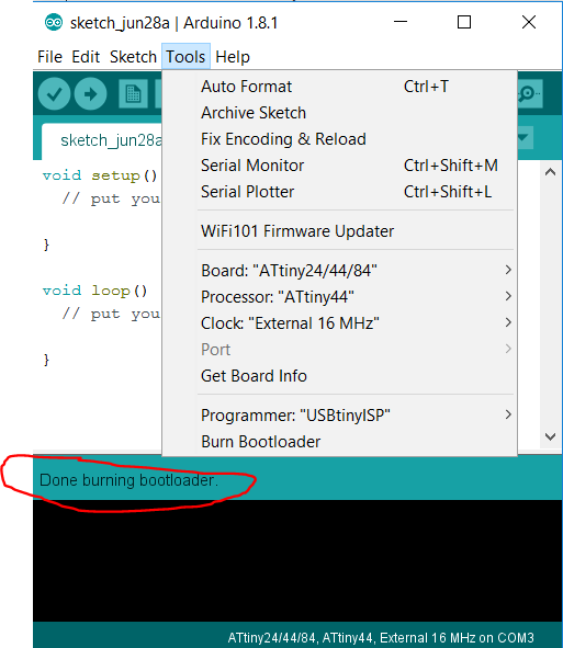
At the arduino IDE, we select tools, burn bootloader. After a few seconds a message showing that you burnt succesfully the bootloader will show
Fig3. - Burning the bootloader
This means we're ready to program the board. For this, we must connect both the ISP and the FTDI cable to allow communication. Here's the wiring
Fig3. - Connections for the programming
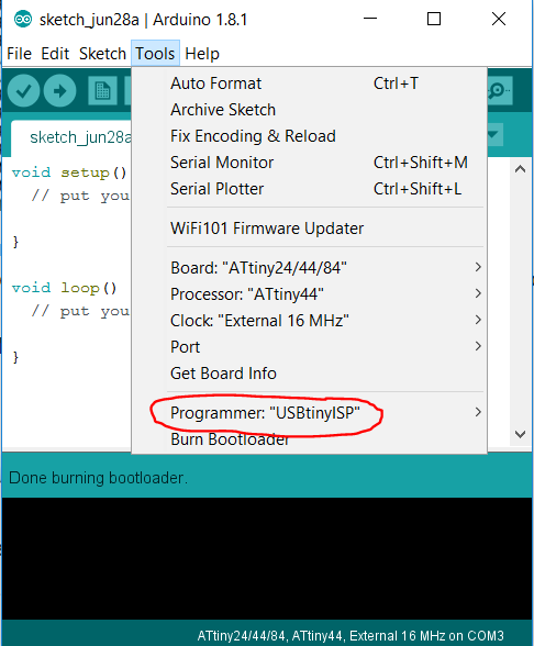
And make sure you select the right programmer
Fig3. - Connections for the programming
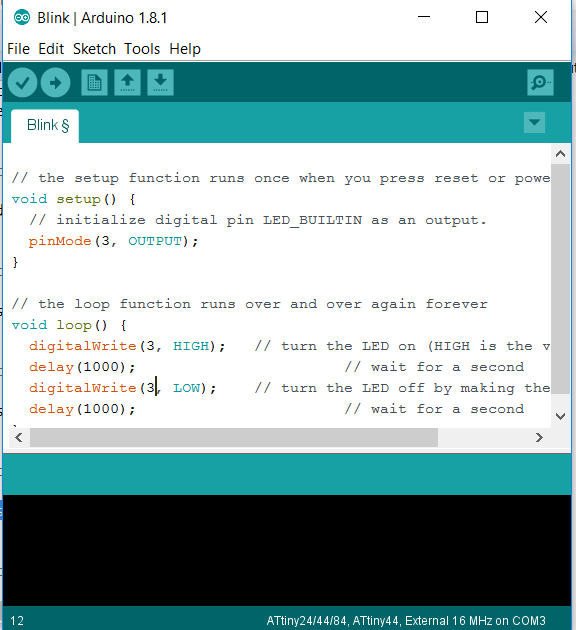
After that, upload the code you wish. In this case I used a simple blink example modified for the pin 3, where the led is located
Fig3. - Code
Finally, the code worked. just supply the board with 5 volts and you're done !
The code:


// the setup function runs once when you press reset or power the board
void setup() {
  // initialize digital pin LED_BUILTIN as an output.
  pinMode(3, OUTPUT);
}

// the loop function runs over and over again forever
void loop() {
  digitalWrite(3, HIGH);   // turn the LED on (HIGH is the voltage level)
  delay(1000);                       // wait for a second
  digitalWrite(3, LOW);    // turn the LED off by making the voltage LOW
  delay(1000);                       // wait for a second
}
This was one of the nost interesting assignments in the entire Academy. All 4 students from the Fab Academy UTEC will work as a team
to build an entire machine (based on MTM snap designed by Nadya peek). The design can be found Here and Here dxf and other files.
I strongly recomend reading Nadya's weblog. It's filled with really great articles and information on Machines that make !
The assignment for this week was:
1) Design a machine (Mechanism + automation)
2) Build the passive parts and operate it manually
And our instructor: Isaac Robles, also an Industrial Engineer. Check out his Fab Academy journey
Here.
First Idea
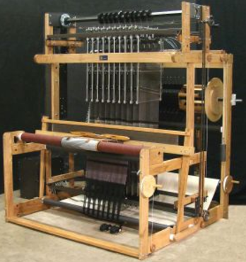
Our first machine idea was made by Alexandra. Her final project was meant to be an automated jaquard loom
Fig1. - Design refferences for a jacquard loom
We've prepaired ourselves to make the machine one week before the assignment, so we had
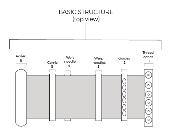
everything set in place. The first design of the machine was, as I mentioned, Alexanda's former final project
Fig2. - Scheme of the jacquard loom machine
I've made the project planning, while Guillermo was designing the 3D models at home
Fig3. - Project planification for the machine
But, we found some difficulties with the functioning of the machine. We found out that, in order for it to work, we needed some
manual operation as the needle needed to move back and forth and be free at the same time.
Fig3. - Project planification for the machine
Change of plans
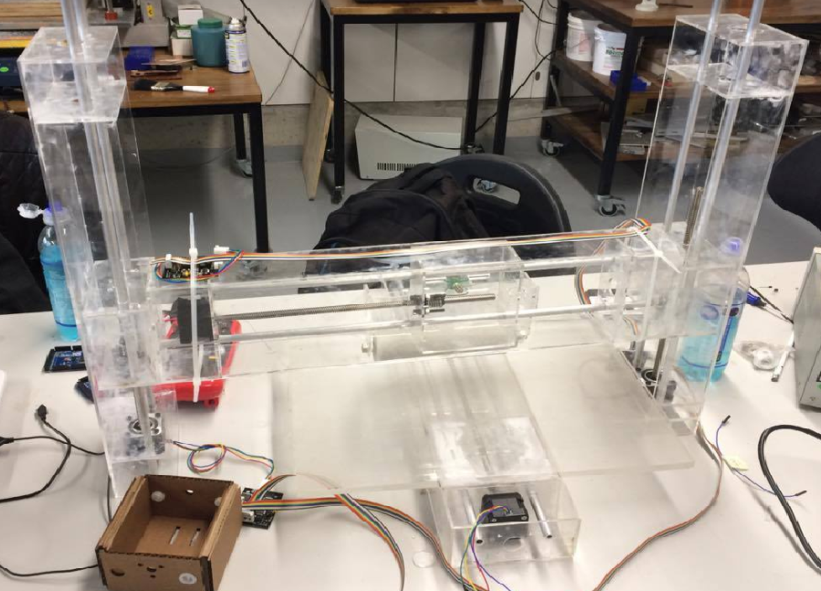
We finally decided to make a Cookie cutter machine after some talking.
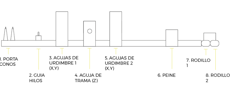
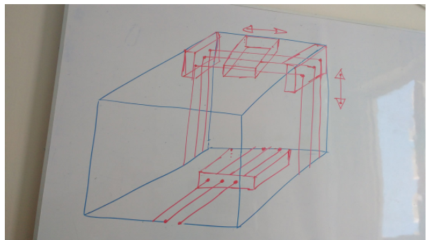
We were provided with 4 gestalt nodes, therefore we had 4 degrees of freedom
Fig4 - Configuration of the machine
I contributed with the 3D design, assembly and animation
Fig5. - assembly
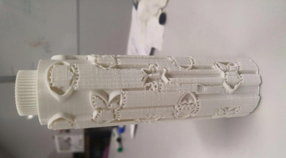
The roller was printed
Fig6. - design of the roller
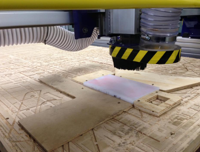
The structure was laser cut using Nadya's designs and used the Shopbot to mill the bed where the
dough will be placed.
Fig7. - Machining
Then we spent all night assembling, and integrating all parts of the machine
Fig9. - parts
And finally, the machine looked like this. And it worked
Fig10. - Final machine
Update
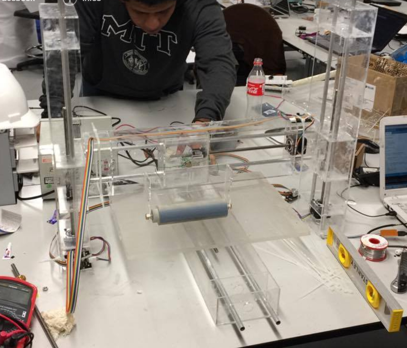
We decided to make it look more aesthetic, so we make the structure in acrylic, again,
laser cutting it's parts. The bed and roller stayed the same as well as the electronics. The result:
Looks beautiful !
Fig2. - The machine
To see more about the machine, the idea and progress visit Fab Lab UTEC's page
Week 10: Output Devices
This week assignment was to add an output device to a microcontroller board I've designed and program it to do
something. I've already had some experience with microcontrollers and electronics in some courses at the university, so I had
some understanding about how output devices work.
An output device is basicly a piece of hardware that process data and translates it into a form readable by humans.
The most common output devices include: leds, buzzers , displays, motors (stepper, DC, AC, servo, etc), speakers, projectors,
screens, sound cards, headphones, etc.
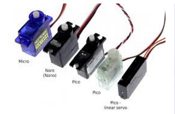
For my final project I'll make a functional prosthetic hand. It means it must move someway. I'll use servomotors as the mechanism of
motion (it'll pull the nylon wire and make the fingers contract). So For this week assignment I'll try to operate a servomotor using a microcontroller, so
I'll be a step closer to the final project.
Fig1. - The micro servo motor I'll use
The microcontroller
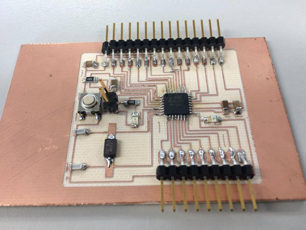
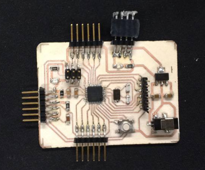
For this and further assignments, I decided to use Daniele Ingrassia's Satshakit (Link here)
that is an Arduino compatible, fabbable board that can be programmed by using the arduino IDE after burning the bootloader. It's recognized as an Arduino UNO instead of
a patched arduino, and has a fair amount of i/o pins. The EAGLE board, schematics and bill of material can be found in the link
Daniele was also a Fab Academy student in 2015, you should really check out his personal academy
web page.
Fig2. - Board of Daniele Ingrassia's Stashakit
I followed the same procedure for making all the boards. First, I milled the CEM-1 board using the Modela MDX-540 cnc and used "Flatcam" software to generate the Gcode. (To see the procedure documentated go to my
Week 4: Electronics production assignment, where I make my first board of the Academy. The ISP).
Then, once the board was milled, I started
soldering all the components. The "bill of materials" found at the satshakit page was really useful. Then, finally, I checked continuity with a multimeter to see if all the traces
were connected the way they are supposed to be.
Fig3. - Milling the boardFig4. - Soldering the boardFig5. - The Satshakit soldered and ready
In order to see if the satsha was working, I just conected the VCC and GND pinouts of the arduino to the 5V and GND pins of the Satshakit.
Fig5. - The Satshakit soldered
The Led's were on... It was working.
The next step was to burn the bootloader to the Atmega 328 processor from the satshakit. We could do this with both arduino or the ISP we made at week 4. The
instructions can be found at the satshakit page.
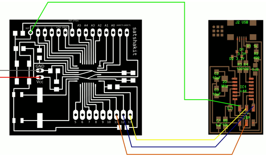
First, we must do the following connections (for the arduino as ISP or the Fab ISP)
Fig6. - Connections to burn the bootloader using an Arduino UNOFig7. - Connections to burn the bootloader using the Fab ISP.
I decided to make 2 boards and try to program with both Arduino and ISP, so I get to have both experiences.
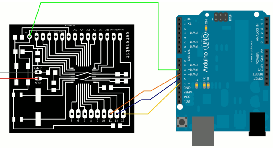
To Burn the bootloader using the Arduino first I made the respective connections between the Satshakit and the Arduino.
Fig8. - Connections Between Satshakit and Arduino.
Once everything is connected, follow these steps to upload Arduino bootloader:
1. open Arduino IDE
Fig9. - Arduino IDE
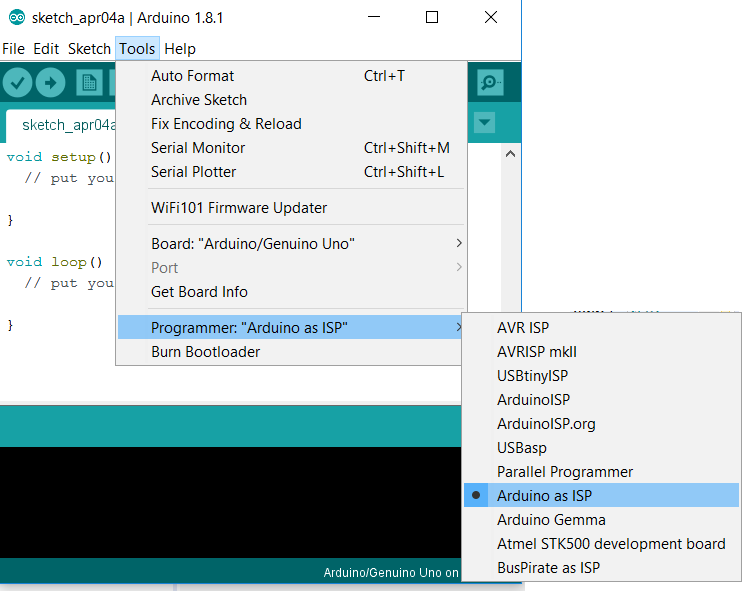
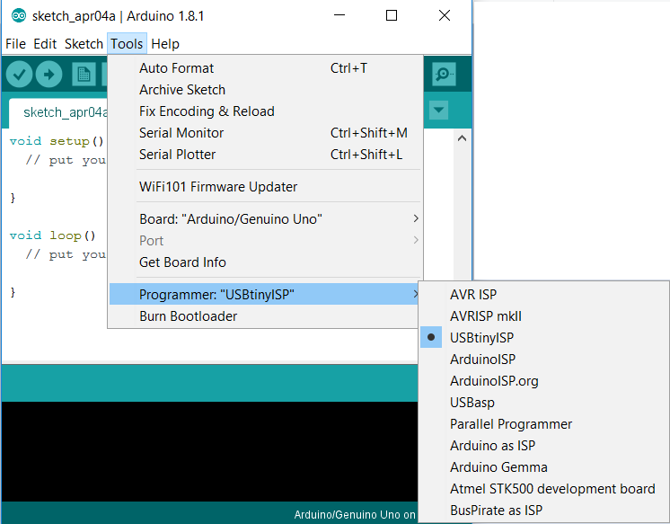
2. select proper programmer by clicking on Tools->Programmer (Select Arduino as ISP)
Fig10. - Arduino As ISP.
3. select Arduino/Genuino UNO as Tools->Board
Fig11. - Selecting the board
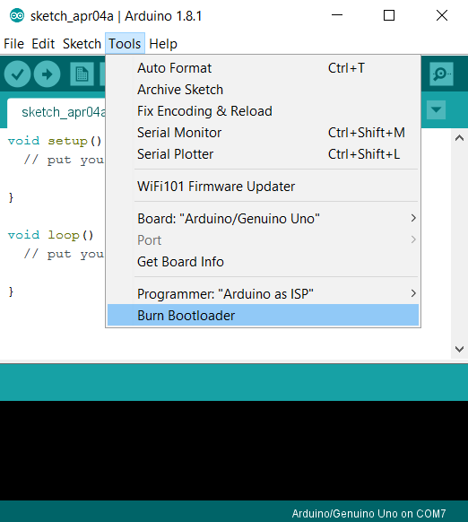
4. click on Tools->Burn Bootloader
Fig12. - Burning the bootloader.
To burn the bootloader using the FabISP just select USBtinyISP as the programmer, then Select Burn Bootloader just like with the Arduino.
Fig13. - Selecting the programmer.
Once the bootloader is burnt, the Satshakit is ready to program.
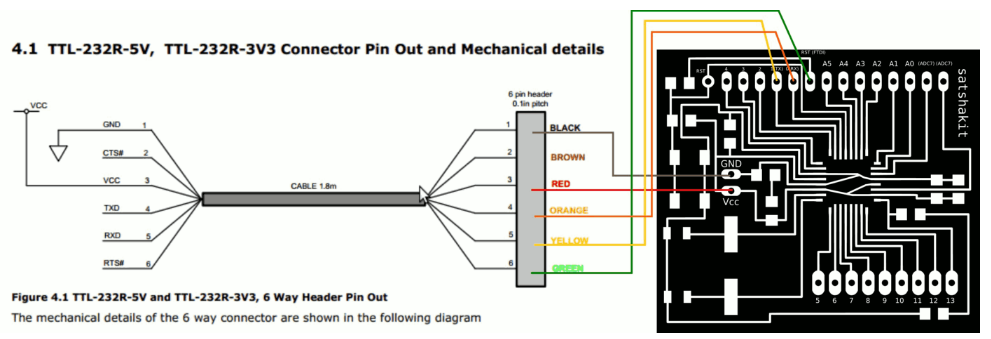
We just need a FTDI cable to program the board directly with the Arduino IDE with the following connection:
Fig14. - FTDI connections for the Satshakit.
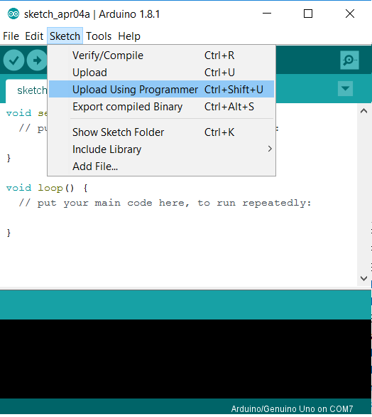
If we do not have an FTDI cable, just select "Upload Using Programmer" in the Sketch menu
Fig15. - Upload .
Controlling the Output Device
As I mentioned before, I decided to control a micro servo motor so I'll be a step closer to my final project. It will be attached to a nylon wire so when it turns, it
pulls the wire and make the finger contract.
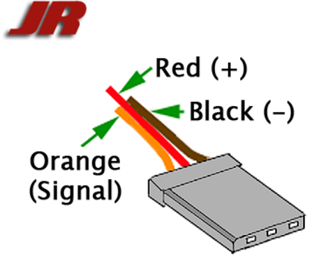
In order to operate an electronic device we must look at its pinout. This is the one from the micro servo:
Fig16. - Pinout of the micro servo I'll use .
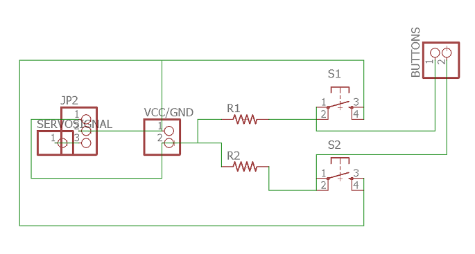
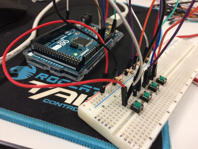
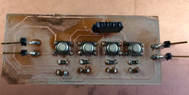
I used 2 simple push buttos to control the direction of the rotation (clockwise or counter-clockwise) And added a 10K resistor to limit the flow of the current to the buttons. The buttons will
simulate the behavior of the myosensor, which will trigger the servo when a pulse is read (the button is pushed)
Here's the connection using Autodesk Circuits or circuits.io. A free Online electronics Lab that can recreate and simulate connections with a virtual
breadboard connection.
Fig17. - Connections using a virtual breadboard from Autodesk Circuit .
Then, I recreated the circuit using a real breadboard, some through hole components and an Arduino UNO
Fig18. - Connections using a breadboard.
Once everything was ok, I used the arduino IDE to program the satshakit to control the servo motor. Here's the code:
The code
							#include
int pos = 0;

Servo servo;
void setup() {
  pinMode(2, INPUT);
  pinMode(3, INPUT);
  servo.attach(9);
}
void loop() {
  if (digitalRead(2) == HIGH && pos < 180) {
    pos++;
    servo.write(pos);
    delay(15);
  }
  if (digitalRead(3) == HIGH && pos > 0) {
    pos--;
    servo.write(pos);
    delay(15);
  }
}
Finally, I uploaded succesfully the code and I was able to control the servo motor with the push button
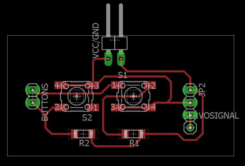
I decided to do a PCB with the components for the servomotor. I used eagle to do the schematic and the board.
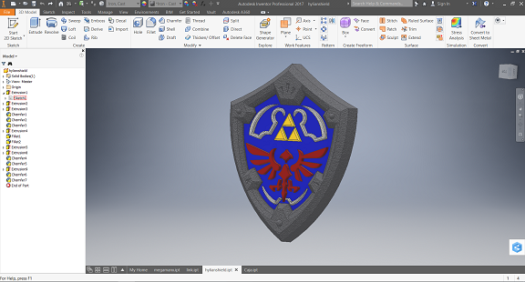
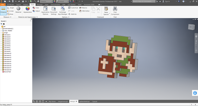
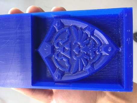
This week assignment was to design a 3D model, machine it, make a mould from it and cast a part from it.
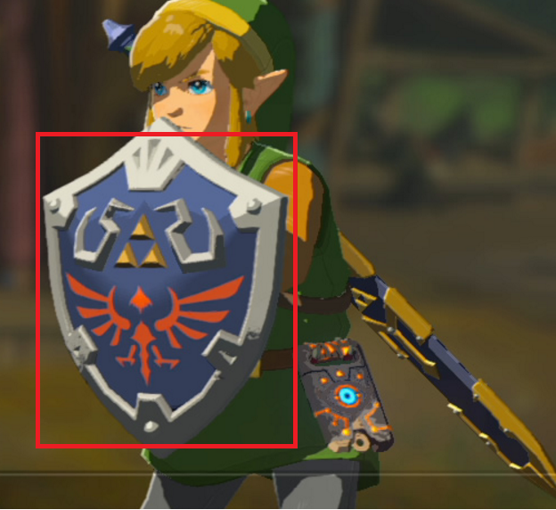
Since I used to play a lot of video games when I was a child, I decided to have a pleasant souvenir and cast the
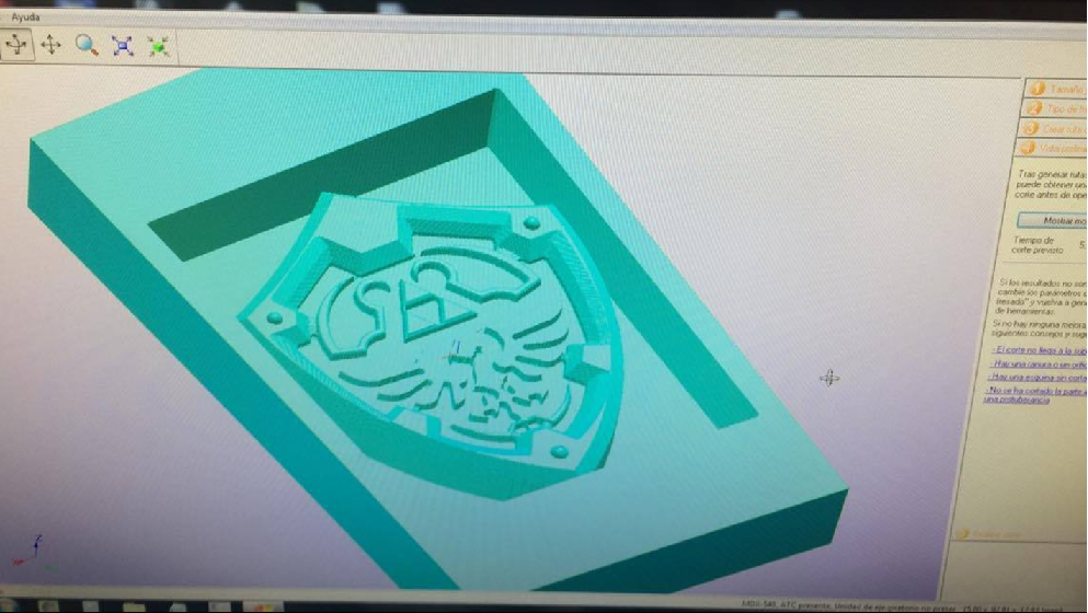
Hylian shield and a pixel art Link from the franchise "Legend of Zelda".
Fig1. - The models I used for this assignment
3D design
I used Autodesk Inventor to design both 3D models taking some drawings from internet as reference.
some images from internet. It took me about an entire day to complete both designs. they finally looked like this:
Fig2. - Base image and my final design of the hylian shieldFig3. - Base image and my final design of Link
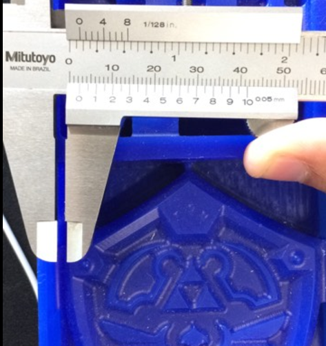
For the machining part, we use a block of blue machinable wax with the dimentions of 77 mm x 160 mm
I chose to mill my part using the Modella MDX-540 cnc milling machine. It was the closest one and the fastest one to do the job.
We used SRP Player as the CAM software. The default software for the modella
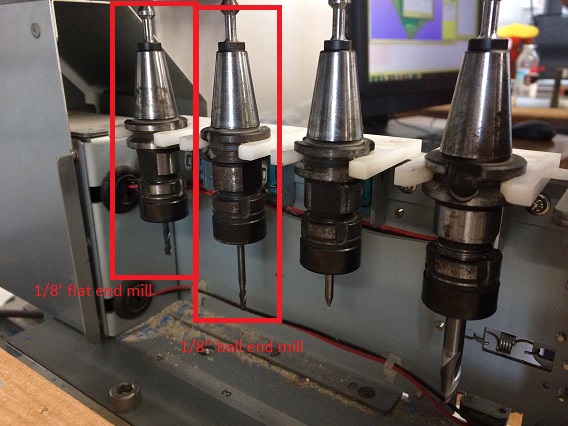
First of all I had to make sure that the endmills were right in place. I used for the milling operation a 1/8'' flat end mill. and for the finishing, a
1/8'' ball end mill. They were both set in the positions 3 and 4 respectively.
Fig4. - Endmills
Then we put the block of wax in the modella using 4 alluminium sheets to assure it won't move.
Fig5. - Block put in place
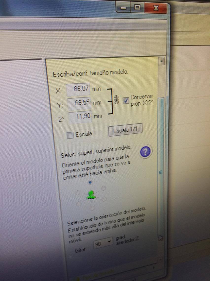
Machining
Then we open the SRP Player to import the STL files of the design. we set the parameters such as dimention of the
design (x, y and z), the endmills, etc.
Fig6. - SRP interface
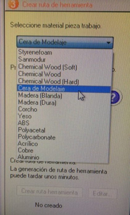
Then, we need to input the material that's going to be milled. This time we'll be using Moulding Wax,
Because of its easy and fast machine and it's waxy properties that allows retiring moulds fast.
Fig7. - Input the material
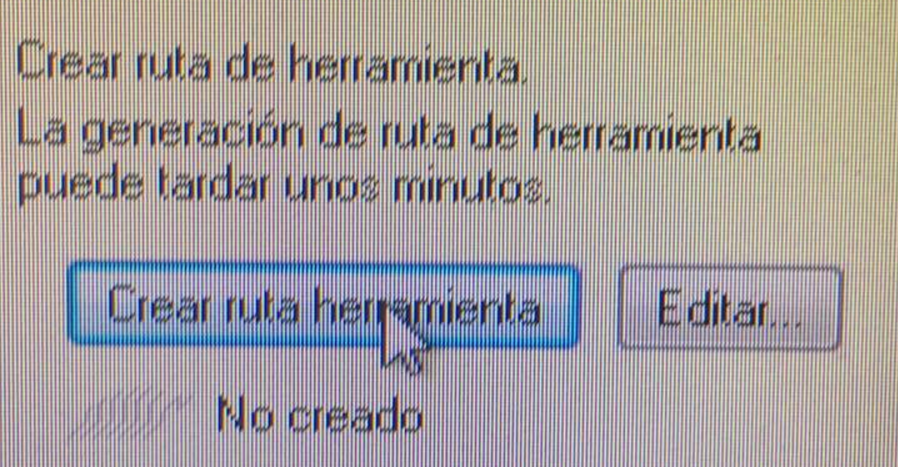
SRP player generates the toolpath automatically by selecting the option. You can see how will it be
milled on the screen interface.
Fig7. - Milling route generated
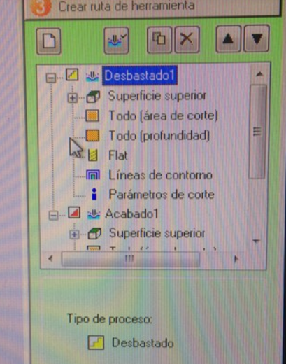
2 types of jobs are recommended for milling high finishing designs. these are: Milling and finishing. SRP
generates the toolpath for both jobs. we input some more parameters of the mill and then It's ready to
be machined !
These are the recommended toolpath parameters for the milling operation
Fig8. - Toolpath parameters for the milling
And for the finishing
Fig9. - Toolpath parameters for the finishing
After that, we move to the initial settings of the Modela. We needed to measure the lenght of each endmill, set the modella in RML mode, and set the zero point of the machining
Fig10. - Measuring the endmills Fig11. - Setting the the modella in RML mode Fig12. - Zeroing the modella
The zero point will be this time at the exact center of the design.
As mentioned before, there will be 2 types of operation: the milling itself and the finishing.
The milling will give the flat form of the piece, and the finishing operation will give the curved texture.
Fig10. - the design being machined
It took about 2 hours to complete all the operations. and finally, the wax mold was made
Fig11. - Wax mold finished
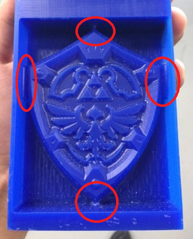
Update
Some gaps between the model and the mould walls were generated after the machining as we could observe
Fig12 - Gaps generated
This happenned because the endmill we used was too wide for the mould and material we used. I set the paraters so that the model
would fit exact into the material (model had 80 x 65 mm and the material was 150 (ok) x 75mm. This results in a 10 mm space for the
walls to fit in, as there must be 2 walls each will only be 5mm thick without giving the model the right space to be machined. The srp player
calculated that the endmill would be too thick to fit in and that's why It leaves that place without machining. The result: the gaps).
Fig113 - dimentions of the walls and gaps
Althought this happenned, it's not critical, as I solved it by printing a frame in which the mould would fit perfectly and allows the
correct cast.
This didn't happen for the second mould I made. Lesson Learnt !
Fig11. - Second mould
Moulding
I used Sorta-clear-37, a water transliçucent Silicone rubber compound to create the Negative Mould. It consists on 2 compounds:
Part A and Part B. Both need to be mixed in a ratio of 1:1 by weight. It means for each kilo of A, there has to be another kilo of B.
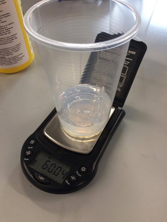
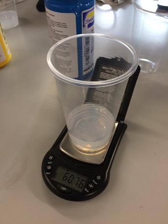
In order to make the mould we needed 2 vases (one for each compound), icecream sticks to stir, Latex gloves and a scale to measure the
quantity of A and B
Fig12. - Materials needed for the moulding
I used the scales to measure the same quantity of A and B
Fig13. - Quantities of A and B
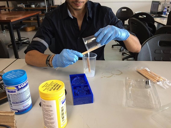
Then I had to mix and stir both parts in the same vase during 3 or 4 minutes intil the mixture has
a good consistency
Fig13. - Mixing both parts
And then, I pour the mixture into the wax mould that was previously machined. I had to make sure that the minimum bubbles formed in the surface. In
order to do that, I tapped the mould to the desk a little it and popped the bubbles that were formed in the surface.
Fig14. - pouring the mixture in the mould Fig15. - pouring the mixture in the mould
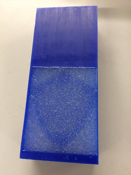
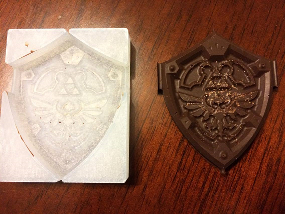
The cure time was 4 hours. and then I was able to retire the Negative mould from the possitive one
Fig16. - Positive and Negative moulds
Finally, I got my negative mould with a high level of details
Fig16. - Positive and Negative moulds
Casting
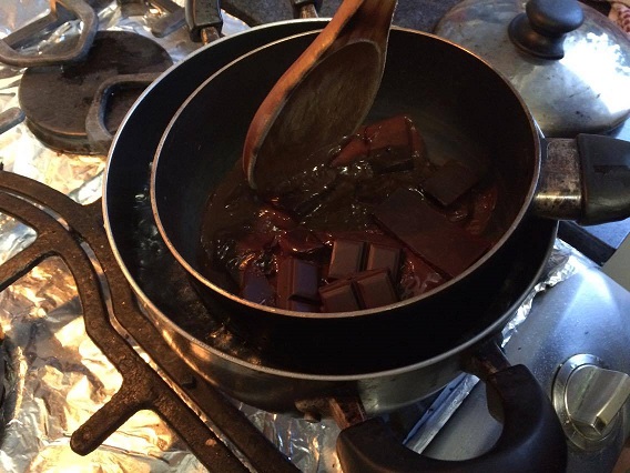
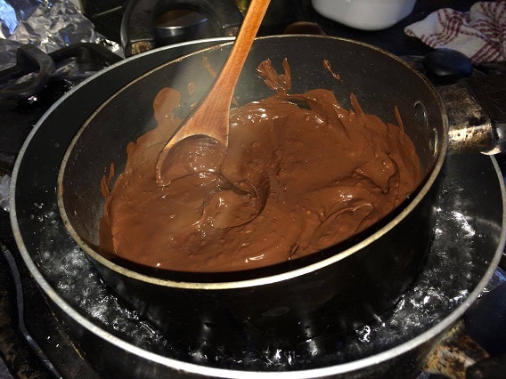
A wide options of material were available here at the lab, but I chose to cast my design in chocolate cover. I wanted
to see how good it ends up being and maybe, make more for my friends :)
First of all I water bathed the chocolate cover to melt it and get a uniform consistency.
Fig17. - Melting the chocolate cover
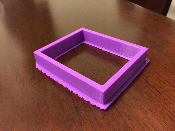
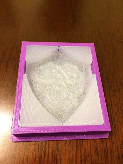
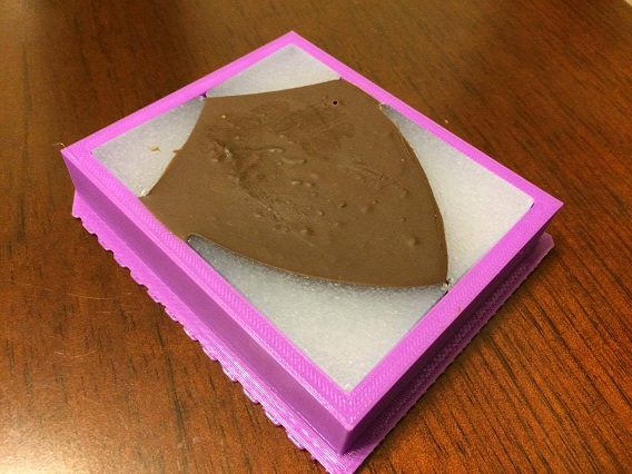
The negative mould had some gaps where the chocolate could exit, so I designed a frame for the mould so the
chocolate would stay in place and take the desired form. I 3D printed it In PLA because it's food safe as well as the Sorta-Clear 37
Fig18. - Frame for the mould Fig19. - It fitted perfectly
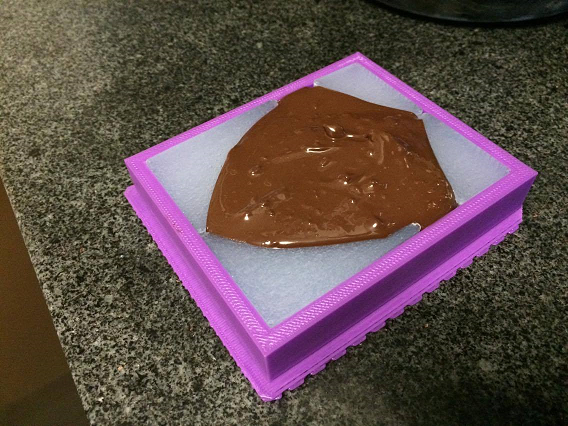
Then I proceded to do the casting itself. I poured the melted chocolate into the negative mould carefully.
Fig20. - Pouring the chocolate into the mold
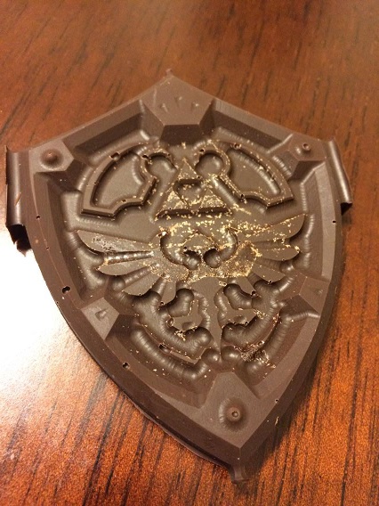
Chocolate cover solidifies in minutes, I let it cure for 30 minutes to assure it's complete solid state and cool temperature and proceeded to
retire the chocolate off the mold with care.
Fig21. - Taking off the chocolate from the mold
Finally, I got my hylian shield chocolate piece with an excellent level of details. It was great to see that you can create something you love
with different methods and using different materials !
This week assignment was to measure something from an input device (a sensor), add it to a microcontroller board that I've designed and control something
through it. I've worked with some sensors before, so I wanted to do something different this time, so I decided to make my own sensor.
I decided to make a capacitive touch sensor out of graphite (pencil traces). I was really curious how It'd end. I found a tutorial on
This page, so I gave it a try.
PCB Design
The tutorial showed the step by step arduino setting for the cap touch sensor, but we were intended to do a cuircuit board, so I made one out of the Hello World board by
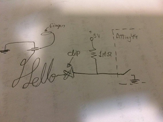
Neil. The theory was simple, when you touch a conductive object, you create a degree of capacitance (the hability to store charge). The higher the capacitance, the longer it will take
the conductive material to be pulled up to the high state. That high state is accomplish thorough a resistor.
Here's an schematic example of the functionality of the capacitive sensor.
Fig1. - Schematic example of the circuit
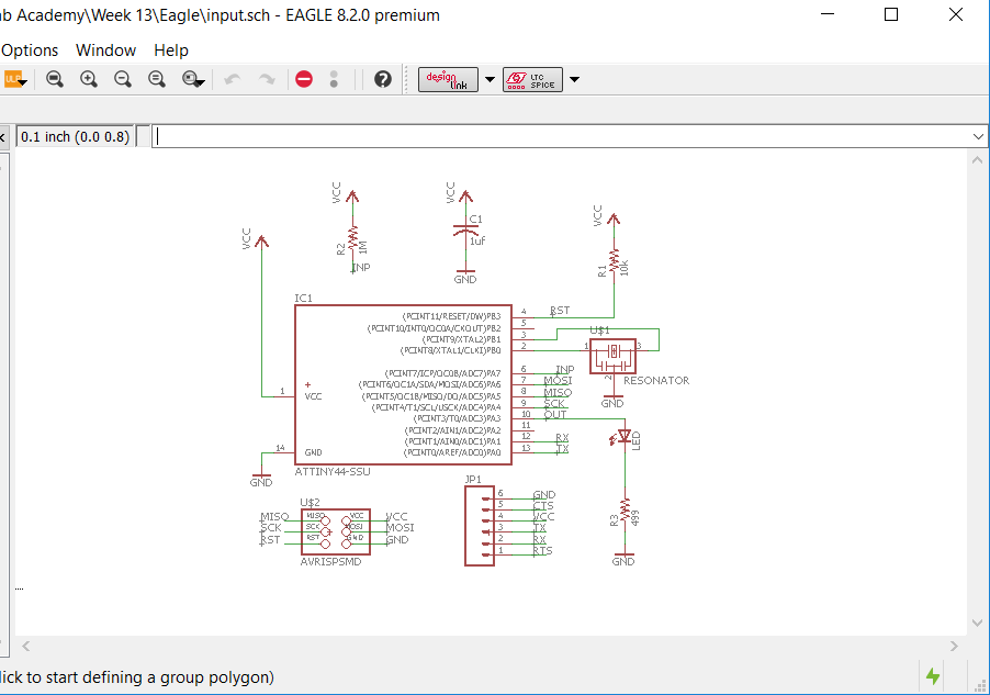
I then chose to modify the Hello world board and add a trail to be soldered to a wire that will be connected to the paper clip, the one
that makes contact with the graphite with EAGLE
Fig2. - EAGLE board and schematic
After a couple of times trying to mill with the Modella, I finally got it done and soldered.
Fig3. - Circuit board
The connections
Here's an example of the connections with an arduino.
Fig4. - Connections using an arduino
And a video showing how it worked with an arduino
The Code
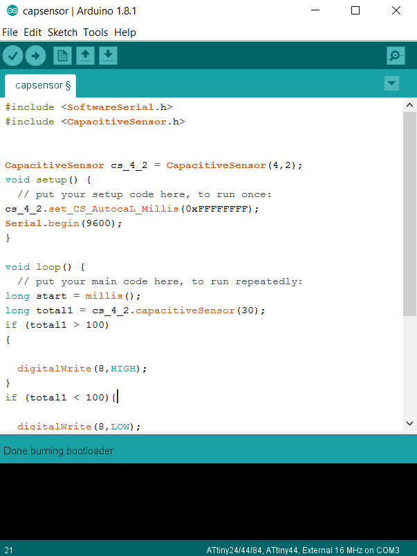
In order to program using the Arduino IDE, I had to burn the bootloader from the attiny44 using the FabISP from electronics production.
I took the code from the example page I listed before with some modifications:
include the SoftwareSerial library: put "#include " at the beginning of your code.
immediately after the include line, type "SoftwareSerial mySerial(0, 1);". This initializes the rx and tx pins to 0 and 1, respectively (this corresponds to 12 and 13 on the attiny44). if you're using other pins for tx and rx, your code should reflect that.
in your setup() function, start up serial communication with "mySerial.begin(9600)". you can change 9600 to another baud rate; i find that 9600 works consistently and well on the attiny.
any time you want to send something to the serial console, use "mySerial.print(thing)" or "mySerial.println(thing)" (but replace "thing" with what you actually want to send).
Fig5. - Arduino CodeThe code
#include
SoftwareSerial mySerial(0, 1);

// Pin for the LED
int LEDPin = 3;
// Pin to connect to the drawing/sensor
int capSensePin = 7;

// Value the sensor needs to read in order to trigger a
// touch. Takes ten samples over a five-second period
// from the touch sensor; chooses the maximum sample
// and sets it to the cutoff value. During this five-
// second setup the sensor should not be touched.
int values = 0;
int capPin;
int get_cutoff() {
  for (int i=0; i<10; i++){
    capPin = readCapacitivePin(capSensePin);
    if (capPin > values) {
      values = capPin;
    delay(500);
    }
  }
  return values;
}

int touchedCutoff;

void setup(){
  mySerial.begin(9600);
  // Set up the LED
  pinMode(LEDPin, OUTPUT);
  digitalWrite(LEDPin, LOW);
  // Get and print the cutoff value.
  touchedCutoff = get_cutoff();
  mySerial.print("Cutoff value: ");
  mySerial.println(touchedCutoff);
}

void loop(){
  // If the capacitive sensor reads above the cutoff,
  // turn on the LED
  if (readCapacitivePin(capSensePin) > touchedCutoff) {
    digitalWrite(LEDPin, HIGH);
  }
  else {
    digitalWrite(LEDPin, LOW);
  }

  // Uncomment below to print the value of the sensor every
  // 500 ms. It took up too much space in memory for the attiny44.
  //if ( (millis() % 500) == 0){
    //mySerial.print("Capacitive Sensor on pin 7 reads: ");
    //mySerial.println(readCapacitivePin(capSensePin));
  //}
}

// readCapacitivePin
//  Input: pin number
//  Output: A number from 0 to 17 expressing
//          how much capacitance is on the pin
//  When you touch the pin, or whatever you have
//  attached to it, the number will increase.
//  In order for this to work, there needs to be a
//  >= 1 Megaohm pull-up resistor to VCC (5V).

uint8_t readCapacitivePin(int pinToMeasure){
  // Declare a variable which will hold the PORT,
  // PIN, and DDR registers.
  volatile uint8_t* port;
  volatile uint8_t* ddr;
  volatile uint8_t* pin;
  // Translate the input pin number to the actual register
  // location. Bitmask chooses which bit we want to look at.
  // Attiny44 only has one 8-bit port, Port A (Port B is 4
  // bits wide), so we need to use Port A and its corresponding
  // DDR and PIN values.
  byte bitmask;
  port = &PORTA;
  ddr = &DDRA;
  bitmask = 1 << pinToMeasure;
  pin = &PINA;

  // Discharge the pin by setting it as an output (and writing it low)
  *port &= ~(bitmask);
  *ddr  |= bitmask;
  delay(1);
  // Make the pin an input WITHOUT the internal pull-up on
  *ddr &= ~(bitmask);
  // Now see how long the pin takes to get pulled up
  int cycles = 16000;
  for(int i = 0; i < cycles; i++){
    if (*pin & bitmask){
      cycles = i;
      break;
    }
  }
  // Discharge the pin again by setting it low and as output.
  // It's important to leave the pins low if you want to
  // be able to touch more than 1 sensor at a time - if
  // the sensor is left pulled high, when you touch
  // two sensors, your body will transfer the charge between
  // sensors.
  *port &= ~(bitmask);
  *ddr  |= bitmask;

  return cycles;
}
Here's the functioning of the board with the capacitive touch sensor from graphite
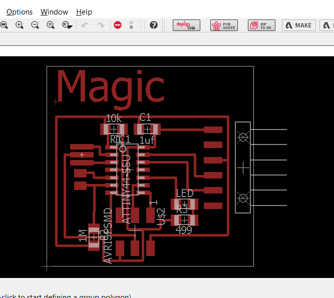
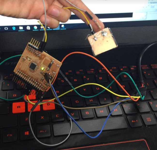
Finally, I wanted to give it a try to the other type of capacitive sensor made of pure copper
Fig5. - Capacitive sensor board and schematic
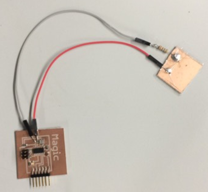
Here the board
Fig6. - Connections
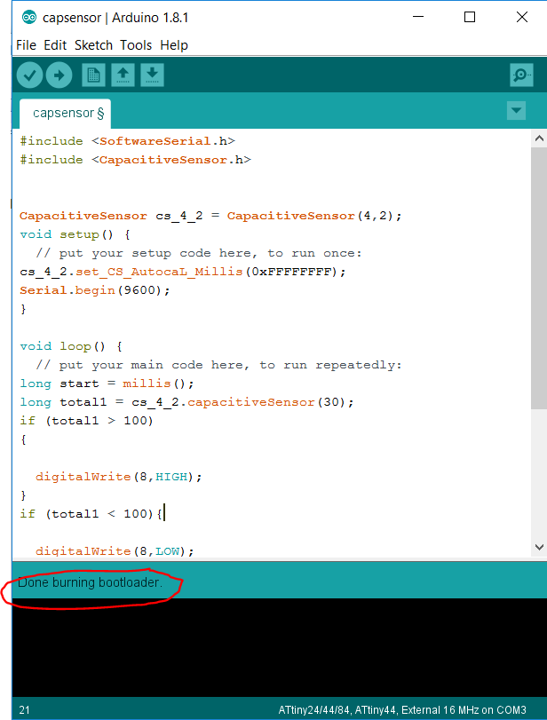
As for the software settings, I first burnt the bootloader as always using the following configuration:
Fig7. - Configuration for the bootloader
No soldering error
Fig8. - Configuration for the bootloader
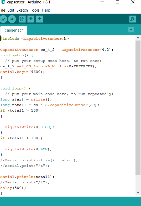
And the arduino code, this time I included the capacitive sensor library. It worked a bit
different because this time each sensor required the use of 2 pins of the arduino, and the Software.Serial library for the
attiny to read values through the serial monitor.
Fig8. - Code of the capacitive sensor
The test, it didn't work, The attiny44 doesn't allow any serial comunication with through the serial port. That's why I decided to
do another controller, this time with a atmega328p as the controller. It allows serial comunication through the serial port, so I made a
controller with 2 pinout free for the capacitive sensor to work.
Fig9. - Connections of the board
And I test it. It worked smoothly. As I touch the copper sensor, the serial ports reads higher value, voila
This week assignment was to design a 3D model (in ft2) and produce a fiber composite part in it. In addition, we need to
read de Material Safety Data Sheet (MSDS) and the Technical Data sheet (TDS) for the chosen resins.
The Design
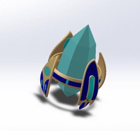
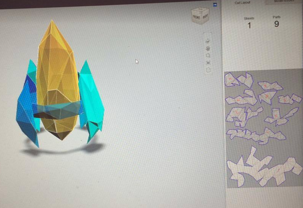
For this assignment I decided to make a Protoss pylon from Starcraft. This time I used solidworks.
Fig1. - Original and Design of the pylon in solidworks
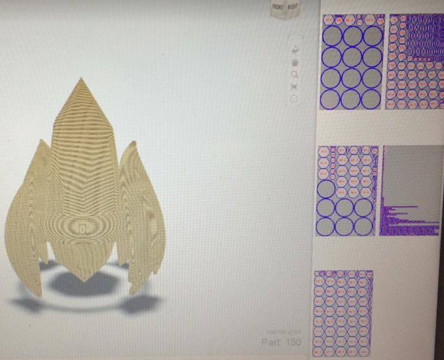
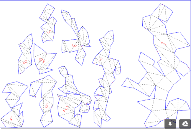
As it was big, I prefered to parametric laser cut it. for that I used slicer for fusion 360. It generates DXF files from stl
I used cardboard for the bending design
Fig2. - Laser cut files from slicer for fusion360
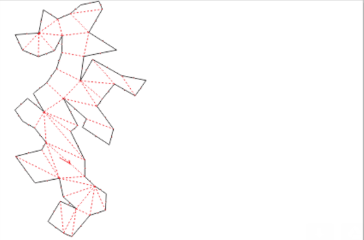
for the support. I wanted it to be rigid. so I made them from plywood
Fig3. - Laser cut files from slicer for fusion360
The Machining
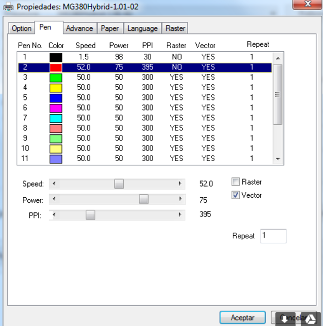
So we set up the corel draw for the first cut
Fig4. - Files set in corel
change the colour to give the right parameters
Fig5. - changing the colour
and set the parameters. the black lines will be vector cut, so it will be a clean cut. The red one is a raster so it bends over them
Fig5. - parameters for the cut
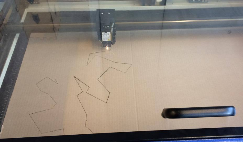
And the cutting takes place
Fig6. - cutting
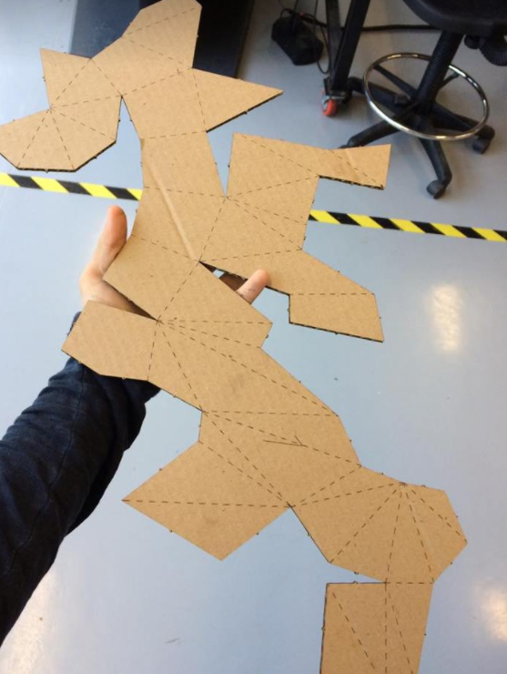
This is the result of the cut
Fig7. - part cut
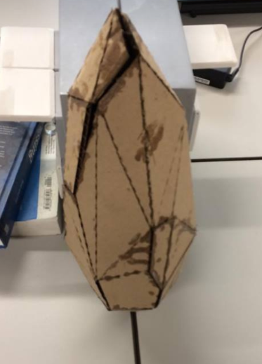
And the final part that is going to be a composite
Fig8. - Part ready
The support will be machined later on, we don't need them for this assignment.
Despite the dimentions set at solidworks. I made sure that the model will be 35 x 60 x 60 cm
in the slicer. that generates automatically the number of sheets of cardboard that I'll be using.
Setting up the fibers
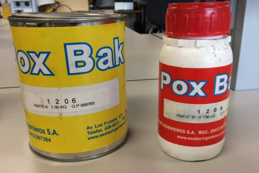
The resin we used was "Pox Bak", we acquired locally:
The material safety datasheet can be found here:
PoxBak MSDS
Basically, the MSDS says that PoxBak 1206 is an epoxic resin that needs to be mixed both parths to get it hard.
It's used in the fabrication of moulds, fundition models, toolings and prototyping. It's mixed in a ratio of 100 - 20 and has a cure
time of 45 min approx. Other mechanical properties include:
Fig9. - The resin
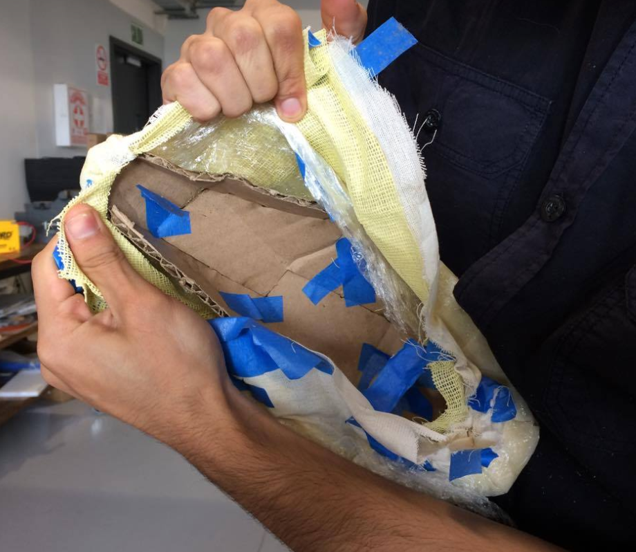
I set my working area with all the materials needed for the compo. We used yute fiber and cotton fiber because when combined, they make
a good trasluscent yet opaque finish that, when a light is lighting inside it gives a nice finish (if it's blue light well, It'd be like a pylon !).
And the extra film paper will give it a crystal like finish aswell.
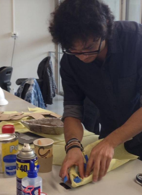
I used some vaselyne, MD40 and film plastic to lubricate the mould and make it easy to retire. I cut the mould in half so we can
actually retire it off the composite
Fig10. - All materials needed for the composite
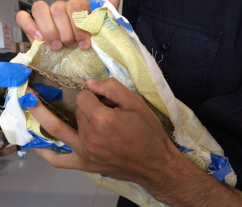
First thing to do was to cover the mould with film plastic. This will make it easier to retire the mould off the
composite when it finishes curing.
Fig11. - covering
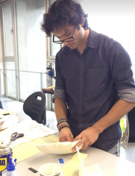
Then, put some vasoeline and cover with both fibers. Yute goes first and cotton goes second. To keep them in place I hold them
with some masking tape in the inside of the mould. This part won't have any resin ant therefore won't be part of the composites. They'll be cut off
afterwards.
Fig12. - covering
here's the result
Fig13. - covered
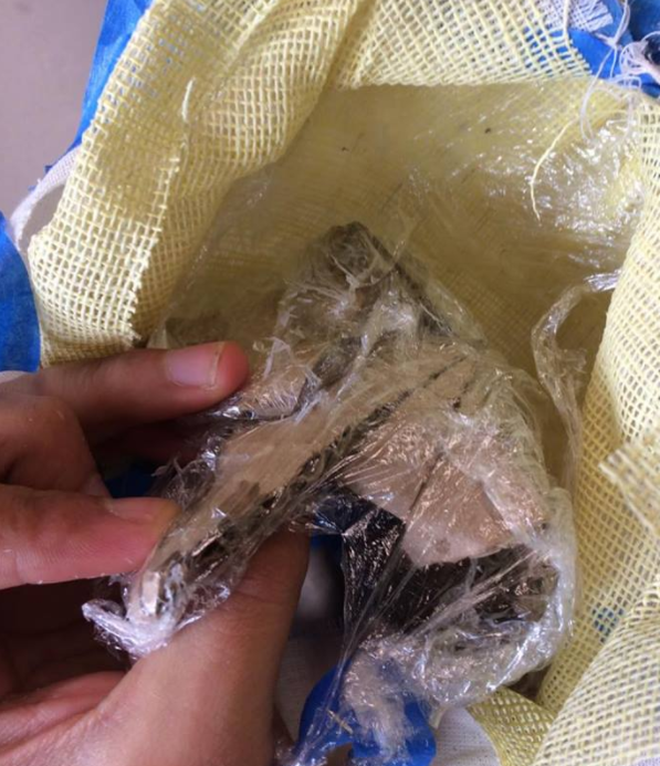
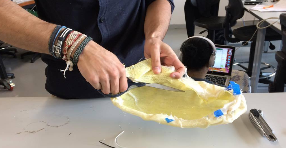
The Composite
Once our fibers are set in place, the composite process takes place. To do this I followed a custom Way lay-up methode with the
following workflow: Preparation of the resin, Painting of the fibers with the mixture, Compression to squeeze to squeeze the excess resin out of the fiber with film plastic,
cure of the resin, extraction of the mould, and extraction of the excess fiber.
I started with the preparation of the resin in a ratio of 100 - 20 of weight and proceed to paint the fiber preparation:
Fig14. - putting the resin
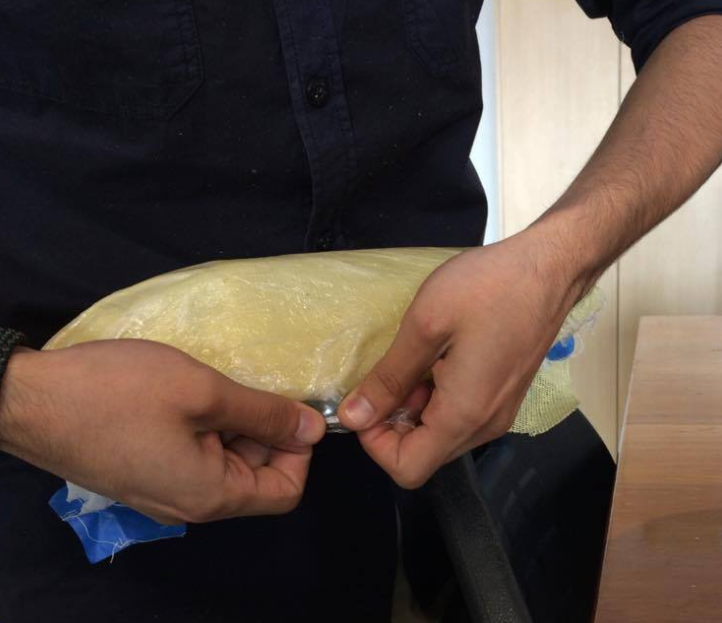
Then, compress the resin holding the film plastic tight into the mould. This will help spread more uniformly the resin
through the fiber and remove the excess on the sides.
Fig15. - Compression using plastic film
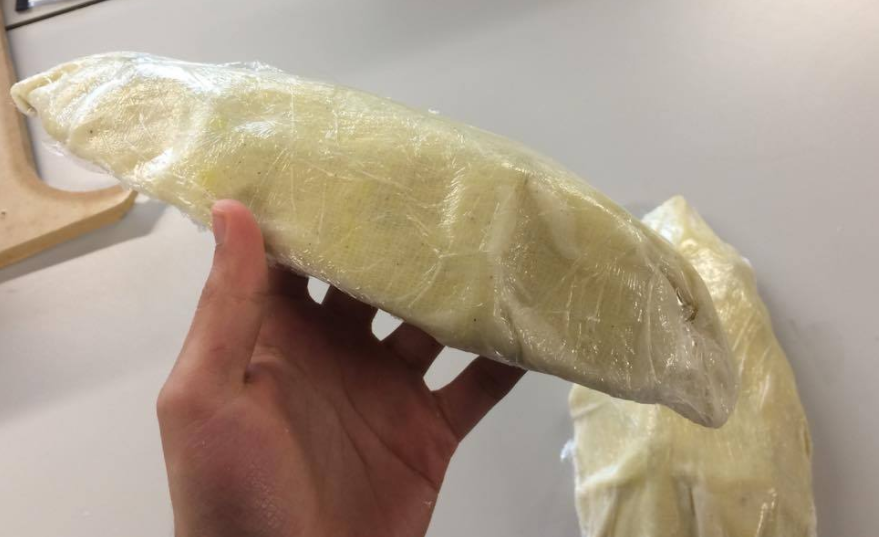
And let it cure. The datasheet says 45 min, but I left it 1 entire night.
Fig15. - curing
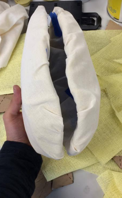
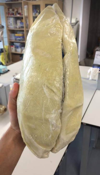
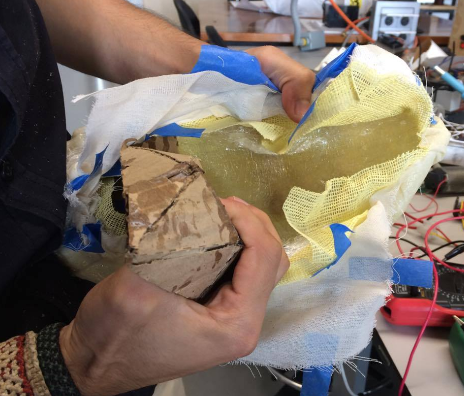
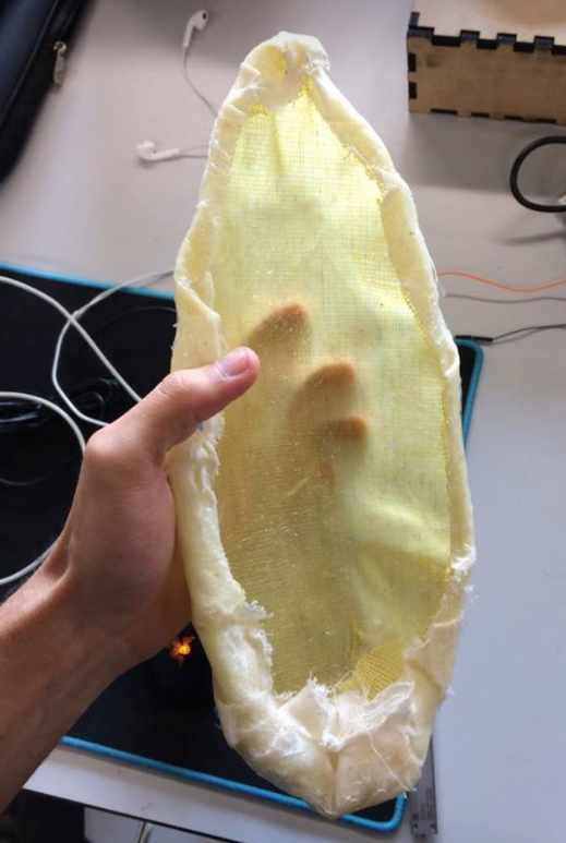
After the resin cured, we obtained a hard yet light composite fiber with the mould inside
Fig16. - Composite fiber with the mould inside.
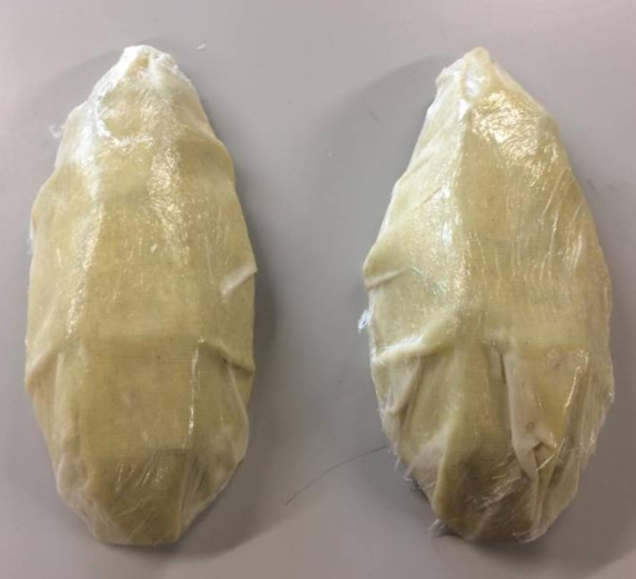
Now we move to the extraction of the mould. This part was so simple thanks to the first layer
of plastic film I wrapped to the mould
Fig16. - Extraction of the mould
We retire the first layer of film plastic aswell
Fig16. - Extraction of the first layer of film plastic
But as expected, some excess of fibers were left in the composites..
Fig16. - remainings of fibers
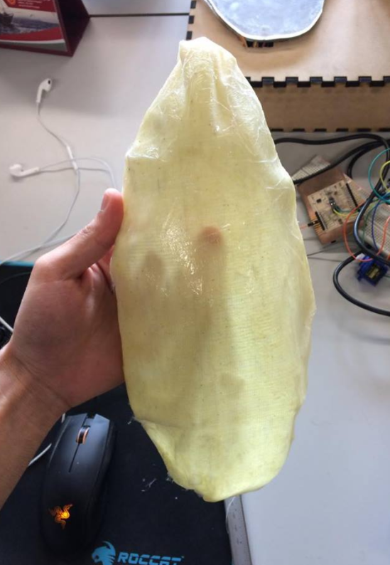
But no problem at all, just
cut those remainings off the model
Fig16. - removing the remainings of the fibers
and finally, we obtain a hard yet light design out of 2 fibers with the traslucent finish I wanted
Fig16. - Fiber composite complete
Update
There are other methods for the compression parts that I found feasable for models like this one:
First, you could generate the laser cut files for the compression mould (scaling it 1.05x the size of the original mould). The second
one is to design the compression mould in a 3D software with .STL format and machine it.
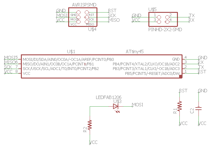
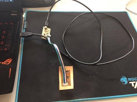
This week assignment was to design and build a wired &/or wireless network
connecting at least two processors, So I decided at first to build the I2C network using the Hello.I2C.45 board
from the Academy page, but after finding some programming difficulties (I only use Windows OS, which difficults me in most of the programming), I
decided to build the Serial bus Network instead.
The Boards
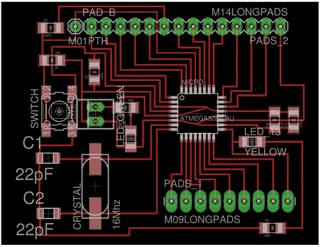
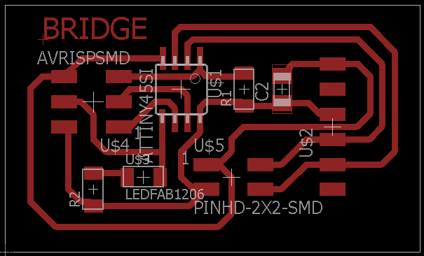
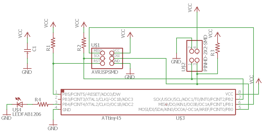
I started designing the schematic of the board using EAGLE as I was already familiarized with the software and the fab library.
It didn't take me long to complete both schematic and board:
Fig1. - The schematic for the bridgeFig2. - The board for the bridgeFig3. - The schematic for the nodesFig4. - The board for the nodes
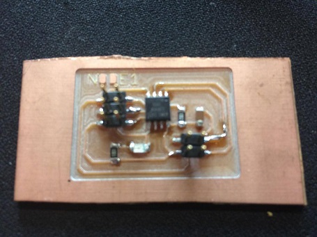
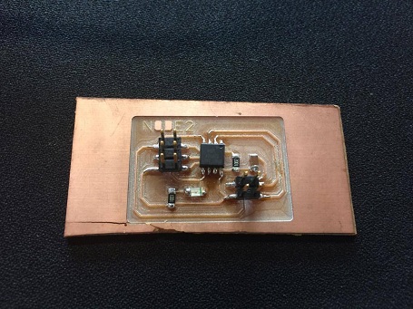
When I had the files ready, I proceeded to mill them with the Modela MDX 540. The cam software
I used for this purpose was, as always, Flatcam. I've already mastered the software so the fabrication part
was kinda straight forward for me.
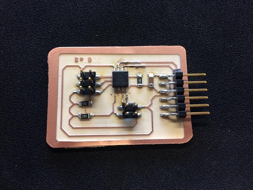
The soldering part was a bit tricky as the microcontroller was smaller than the usual. I had to check continuity a
couple of times with a multimeter, but in the end all went smoothly.
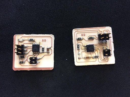
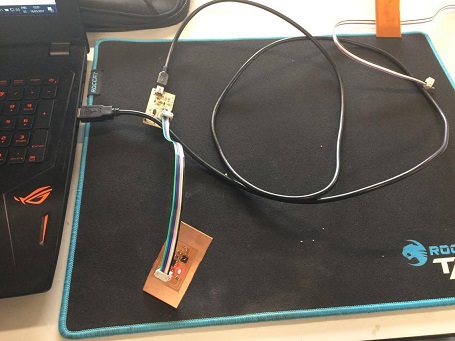
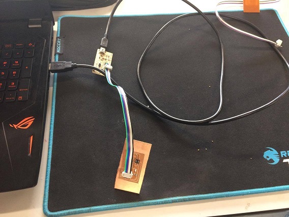
Fig5. - The bridge boardFig6. - Both node 1 and 2 boards
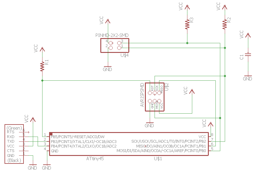
As I said before, I wanted to try the hello I2C board. I drew the schematic and boards for both bridge and node in EAGLE. I even
soldered the components:
Fig7. - The schematic for the bridgeFig8. - The board for the bridgeFig9. - The schematic for the nodesFig10. - The board for the nodesFig11. - The boards soldered
The Network
In order to program the boards, we need to use the FabISP from Electronics Production, the .C file Here,
and the .Make file Here
Before programming the boards, we must change a line of the .C code.
Change the line: #define node_id '0' --> each node needs to have a different number (0, 1, 2, 3 - for each additional node you add.
This time we'll stick to #define node_id '0' for the bridge, #define node_id '1' for Node 1 and #define node_id '2' for Node 2.
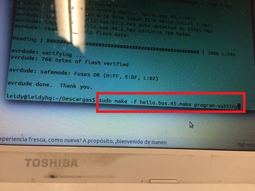
To program each board, we need to conect our ISP to a usb port of the PC, then the ISP connector to each board, then type the command:
Fig12. - Programming of the boards
We do that for either the bridge and both nodes:
Fig13. - Programming of the boards
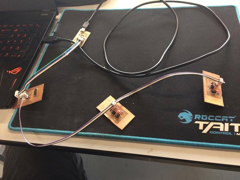
When all the programs are loaded to the boards, we now make the network wiring: We connect the ISP to a usb port of our PC,
we also connect the FTDI cable from the bridge board to another port of the PC. Finally we prepare a triple 2x2 jumper wire for the
bus communication between the bridge and both nodes:
Fig14. - Wiring of the network
Finally, to test the proper connection, we open the Arduino serial port and type whatever command. If you typed 1, then the led from node 1
should blink, if you typed "2", then the node 2 should blink. Here's a video of the network working properly. Piece of cake !
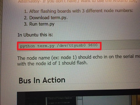
Alternately- If you don't have / want to use the Arduino IDE, you can download the term.py python script and run the program
from the terminal using the following command
This week assignment was to write an application that interfaces with an input or output device that I made, using as many tools as possible. I was
a little bit familiar with Processing environment, but my level wasn't the best, so I decided to learn a little bit more and do some cool stuff with this
powerful tool.
The Interface
As a gamer, I like things to be interactive, so my first idea was to make an interactive interface, yet simple so I won't spend too much time in it, using
Processing.
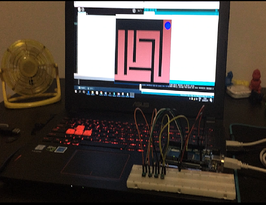
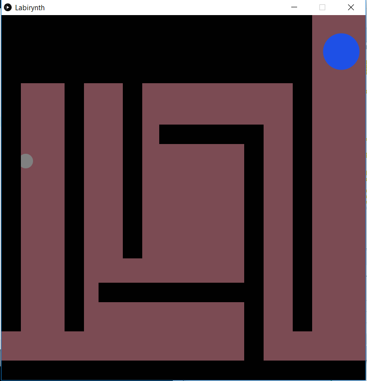
The coding was a little bit tricky, I had to learn a lot of funcitions to make it as I wish. The following code is the one I made for an small Labyrinth game using
"WASD" keyboard keys:
Processing code
ball player;

  wall[] walls;

  void setup() {
    size(750, 750);
    player = new ball(50,300);

    walls = new wall[11];
    walls[0] = new wall(250,0,40,500);
    walls[1] = new wall(500,250,40,500);
    walls[2] = new wall(600,0,40,650);
    walls[3] = new wall(325,225,215,40);
    walls[4] = new wall(200,550,310,40);
    walls[5] = new wall(0,0,40,650);
    walls[6] = new wall(130,0,40,650);
    walls[7] = new wall(250,100,360,40);
    walls[8] = new wall(0,100,300,40);
    walls[9] = new wall(0,710,750,40);
    walls[10] = new wall(0,0,640,100);


   }
void draw() {

  background(123, 75, 83);
  noStroke();

  player.draw();
  player.move(walls);

  for(int i = 0; i < walls.length; i++){
    walls[i].draw();
  }

}

class ball {

  float x;
  float y;

  ball(float _x, float _y){
    x = _x;
    y = _y;
  }

  void draw(){
    fill(128);
    ellipse(x,y,30,30);
    fill(30,80,230);
    ellipse(700,75,75,75);
    if (x>750){
      x = 0;
    }
    if (x<0){
      x = 750;
    }
        if (y>750){
      y = 0;
    }
    if (y<0){
      y = 750;
    }

    if(y<75){
      textSize(30);
      fill(240,30,80);
      background(255,255,255);
      text("You did it!", 600, 700);
    }

  }

  void move(wall[] walls){

    float possibleX = x;
    float possibleY = y;

    if (keyPressed==true) {

      println(key);

      if (key=='d') {
        possibleX= possibleX + 5;
      }
      if (key=='a') {
        possibleX = possibleX - 5;
      }
      if (key=='s') {
        possibleY = possibleY + 5;
      }
      if (key=='w') {
        possibleY = possibleY - 5;
      }
    }

    boolean didCollide = false;
    for(int i = 0; i < walls.length; i++){
      if(possibleX+15 > walls[i].x && possibleX-15 < (walls[i].x + walls[i].w) && possibleY+15 > walls[i].y && possibleY-15 < walls[i].y + walls[i].h){
        didCollide = true;
      }
    }

    if(didCollide == false){
      x = possibleX;
      y = possibleY;
    }

  }
}

class wall {

  float x;
  float y;
  float w;
  float h;

  wall(float _x, float _y, float _w, float _h){
    x = _x;
    y = _y;
    w = _w;
    h = _h;
  }
  void draw(){
    fill(1);
    rect(x,y,w,h);
  }

}
The result ? this beautiful interface for a small labyrinth game:
Fig1. - Screen shows when running the code on processing
This week assignment was to write an application that interfaces with an input or output device that I made, using as many tools as possible. I was
a little bit familiar with Processing environment, but my level wasn't the best, so I decided to learn a little bit more and do some cool stuff with this
powerful tool.
As Mentioned, we were able to control the small ball with "W-A-S-D" hot keys, But we had to comunicate with an input or output device, So, to make things simple,
I decided to controll the movements with simple push buttons that simulate Digital sensors.
The Controller
So, for the hotkeys I decided to use 4 push buttons for all 4 movements (up - down - left - right). and attach the signals to 4 pins of the arduino.
As the microcontroller will read a lot of noise with just the push buttons, I had to use a 10K ohm pull-down resistor for each one of them. Here's the schematic.
Fig2. - The schematic for the push buttons
The connections were made on a breadboard
Fig3. - Conections of the buttonsin a breadboard
Then, I ran a sample digitalread code to assure everything went smoothly
Fig4. - The test code to assure all buttons were conected properly
When opening the serial port we should be able to see an array of four 1s and 0s depending on the
state (high or low) of each button. Note that we can't attach any signal to pin1 because it's dedicated to Tx/Rx communication and
we're using that to get data to the serial port.
Comunicating the interface with the controller
In order to learn to communicate the arduino with processing I followed read a very well explained tutorial on how to comunicate data from an arduino to processing
and vice versa. The tutorial can be found Here
I modified the code a little bit so we use the push button we need and a led to make it more visual. Here's the code
Fig5. - Example code for comunicating processing with arduino
The simplest way to comunicate an arduino with processing is using the Serial port. Processing has a library for this purpose. We just have to make sure
that the data is transfering from one source to another at the same baud rate (9600 worked fine for me)
Fig6. - Example code for comunicating processing with arduino
I made the physical conection with the push button
Fig7. - Conections of the example
It should show in the screen that the button is pressed when we press the push button, as well as turn on the led when we left click in the screen of the
processing and turn it back off when right clicking it as shown in this video
The Game
Finally, knowing to comunicate the arduino with processing, I modified the first code, incluiding the serial library for processing
Processing code
import processing.serial.*;
Serial port;
String valor = "xxx";
int convertido = 2;
ball player;

  wall[] walls;

  void setup() {
    size(750, 750);


    player = new ball(50,300);

    walls = new wall[11];
    walls[0] = new wall(250,0,40,500);
    walls[1] = new wall(500,250,40,500);
    walls[2] = new wall(600,0,40,650);
    walls[3] = new wall(325,225,215,40);
    walls[4] = new wall(200,550,310,40);
    walls[5] = new wall(0,0,40,650);
    walls[6] = new wall(130,0,40,650);
    walls[7] = new wall(250,100,360,40);
    walls[8] = new wall(0,100,300,40);
    walls[9] = new wall(0,710,750,40);
    walls[10] = new wall(0,0,640,100);


   }
void draw() {

  background(123, 75, 83);
  noStroke();

  player.draw();
  player.move(walls);

  for(int i = 0; i < walls.length; i++){
    walls[i].draw();
  }

}

class ball {

  float x;
  float y;

  ball(float _x, float _y){
    x = _x;
    y = _y;
  }

  void draw(){
    fill(128);
    ellipse(x,y,30,30);
    fill(30,80,230);
    ellipse(700,75,75,75);
    if (x>750){
      x = 0;
    }
    if (x<0){
      x = 750;
    }
        if (y>750){
      y = 0;
    }
    if (y<0){
      y = 750;
    }

    if(y<75){
      textSize(30);
      fill(240,30,80);
      background(255,255,255);
      text("You did it!", 600, 700);
    }

  }

  void move(wall[] walls){

    float possibleX = x;
    float possibleY = y;
 convertido = int(valor);
  if (convertido == 3) {
    possibleX= possibleX + 5;
  }
  if (convertido == 1) {
    possibleX= possibleX - 5;
  }
  if (convertido == 4) {
    possibleY= possibleY + 5;
  }
  if (convertido == 2) {
    possibleY= possibleY - 5;
  }
    if (keyPressed==true) {

      println(key);

      if (key=='d') {
        possibleX= possibleX + 5;
      }
      if (key=='a') {
        possibleX = possibleX - 5;
      }
      if (key=='s') {
        possibleY = possibleY + 5;
      }
      if (key=='w') {
        possibleY = possibleY - 5;
      }
    }

    boolean didCollide = false;
    for(int i = 0; i < walls.length; i++){
      if(possibleX+15 > walls[i].x && possibleX-15 < (walls[i].x + walls[i].w) && possibleY+15 > walls[i].y && possibleY-15 < walls[i].y + walls[i].h){
        didCollide = true;
      }
    }

    if(didCollide == false){
      x = possibleX;
      y = possibleY;
    }

  }
}

class wall {

  float x;
  float y;
  float w;
  float h;

  wall(float _x, float _y, float _w, float _h){
    x = _x;
    y = _y;
    w = _w;
    h = _h;
  }
  void draw(){
    fill(1);
    rect(x,y,w,h);
  }

}
void serialEvent (Serial port) {
  valor = port.readStringUntil('.');
  // Remover el punto
  valor = valor.substring(0, valor.length() - 1);
  println("+"+valor+"+");
  }
I also modified the Arduino code because I couldn't get any comunication with the first one. This one is based on the example with a
single button, just adding 3 more buttons to ir :)
Arduino Code
// constants won't change. They're used here to
// set pin numbers:
const int buttonPin1 = 2;     // the number of the pushbutton pin
const int buttonPin2 = 3;
const int buttonPin3 = 4;
const int buttonPin4 = 5;
const int ledPin =  13;      // the number of the LED pin

// variables will change:
int buttonState1 = 0;         // variable for reading the pushbutton status
int buttonState2 = 0;
int buttonState3 = 0;
int buttonState4 = 0;

void setup() {
  // initialize the LED pin as an output:
  pinMode(ledPin, OUTPUT);
  // initialize the pushbutton pin as an input:
  pinMode(buttonPin1, INPUT);
  pinMode(buttonPin2, INPUT);
  pinMode(buttonPin3, INPUT);
  pinMode(buttonPin4, INPUT);
  Serial.begin(9600);
}

void loop(){
  // read the state of the pushbutton value:
  buttonState1 = digitalRead(buttonPin1);
  buttonState2 = digitalRead(buttonPin2);
  buttonState3 = digitalRead(buttonPin3);
  buttonState4 = digitalRead(buttonPin4);

  // check if the pushbutton is pressed.
  // if it is, the buttonState is HIGH:
  if (buttonState1 == HIGH) {
    Serial.print("1.");
    delay(250);
  }
  else if (buttonState2 == HIGH){
    Serial.print("2.");
    delay(250);
  }
  else if (buttonState3 == HIGH){
    Serial.print("3.");
    delay(250);
  }
  else if (buttonState4 == HIGH){
    Serial.print("4.");
    delay(250);
  }
  else {
    Serial.print("0.");
    delay(250);
  }
//  Serial.println();
//  //Serial.print("el boton esta en: ");
//  Serial.print(buttonState);

  //delay(400);
}
It worked in the first attempt !
I finally made a board with 4 Push buttons and connected it to a modified version of fabduino I made in order for it to be the "controller" of the game
Fig15. - Board with 4 push buttons and the modified fabduino
It worked ! here's a video showing the functioning :)
So, Here I'll answer this week's questions about my final project
what will it do?
My project aim to be a functional prosthetic hand that will replace some of the functions of a hand. It'll be controlled by the pulses of
myoelectrodes easily purchaseable in any drug store. The fingers will move by servomotors that will pull thin cables and, therefore, contract themselves
who's done what beforehand?
The only project from past years of the fab academy that ressembles the idea of my final project was Adam Harris project
of a biometric hand. He controlls the fingers of his hand using servomotors and a thin cable aswell, but the design is not intended to be used as prosthetic.
Currently in the market, there are a couple of brands that develops prosthetic hands, for example armdynamics or bebionic. But most of them are
actually really hard to get or are too expensive. There are free downloadable designs on the internet aswell such asthis one from thingiverse. But it's function is limited to be mechanical only.
This project seeks to be a controlled hand that will be accesible for most people who need one.
what materials and components will be required?
Fig1. - Bill of materials of the final project
As for the electronics, I'll need a microcontroller in order to get the things done. It'll be made by me at the fab lab.
where will they come from?
All materials can be easily acquired at local grocery store
The electronic componets will be provided by my fab lab, but if you wish to purchase them they're all
in stock at DigiKey
how much will it cost?
As I mentioned before, I'll be provided with most materials for my final project. The most expensive ones are the servomotors, which costs around 10 dollars each.
The cost of the 3D printing material will vary depending on which printer will be used. It won't exceed the 100 USD as shown in the bill of materials
what parts and systems will be made?
All mechanical parts will be made by me at my fab lab. The hand itself and the finger will be 3D printed, and the wrist grip will be laser cut using mdf.
The electronic board will also be made by me (design, milled and soldered), but the sensors and actuators (myosensor and servomotor) will be bought.
what processes will be used?
For the manufacturing, I'll use 3D printing and laser cutting. I could include some composites for the palm and finger holder.
for the pcb, milling using the MDX-540 Modela.
For the programming, I'll use the arduino IDE and Matlab for the signal filter and amplification.
what tasks need to be completed?
I still have to finish the design of the thumb (proportions and measures), And the conditioning of the signal that I'll get from the sensors.
The programming will be completed as soon as I get a smooth signal.
what questions need to be answered?
Mainly about which muscles controll which tendons of a hand. I need to do some researches and get some information about it.
what is the schedule?
The two weeks coming, I'll be developing a plan for dissemination of my final project, complete the design of it and maybe, already
manufacture all mechanical parts and assemble them. The following weekend I'll work with the electronics and integrate the whole of the project.
how will it be evaluated?
First i'll test that all the electronic inputs + outputs work, next test if the mechanism works right and finally test the whole mechanism and compare the different results.
Week 18: Invention, Intellectual Property and Income
Intellectual Property
Since I intend to make my project free and accesible to most people, I aim to make it Open Source, as people will be
able to use it, modify it and upgrade it until it gets the best design and optimal functioning.
There are a lot of open source licenses to choose. The following are the most common ones
To see all open source licenses by category available clikHere
If I were to choose an open source License, it'd be the MIT license. A short and simple permissive license with conditions only requiring preservation of copyright and license notices. Licensed works, modifications, and larger works may be distributed under different terms and without source code.
MIT license
Another good option I thought of was licence the project under the Creative Common's licence. So I'd get credited when It's used for non comercial purposes.
I think this type of licence would be the proper one for this project because I want people to improve the design and make it prosthetic, but acknowledging me as the
designer of that beautiful hand. More information could be found here https://creativecommons.org/
To patent it it's not an option because it implies commertial commitment and I doubt someone would like to buy a DIY robotic hand. It also implies industrialisation, which
I lack of experience and resources
Dissemination
As for the dissemination, If the project is feasable, I plan to make a few hands and get them to some rehab centers and, little by little, make it known by
local people that there's an affordable alternative to replace, or at least recover the lifestyle they'd have with all of their limbs
This article will be about how I planned to achieve the final project I set to myself during week 1, how I completed the tasks I planned and
what's to come for the last weeks
what is the deadline? How much time do I have left?
Deadline of the final project will come this 21th june. By then I must have all the integration of
the project, have already made my slide and 1 minute video of the project.
Plus, I must be able to talk about each part of the project in front of all classes and be
able to answer the questions that people will throw.
what tasks have been completed, and what tasks remain?
Looking in retrospective to week 1, the gantt diagram worked pretty well. At least for the parts of the design.
I managed to 3D design most parts in time and printed them. For the Laser cutting, I still had to do some researches about live hinges and parametric design, plus, think about how to integrate that to the final project. For the electronics part I already have the sensors (EMG electrodes) and some papers about signal conditioning, amplification and filtering. I’m still doing the tests because I don’t manage to get a smooth and strong enough signal to be read by my microcontroller.
I already designed the microcontroller that I’ll be using for this project. I used atmega 328p as the processor for the number of pinouts and the serial communication it allows.
The integration part needs still to be completed. I’ll be doing that as soon as I get all the electronics working.
UPDATE
I changed the focus of my final project ! As I couldn’t get the signal amplification well with the myosensors I decided to change them with piezoelectric ones and change the project name (instead of prosthetic it’ll be “robotic”). I designed a case and a support for that to happen.
how will I complete the remaining tasks in time?
The integration will be made next week. With the help of my classmates. As I already have all the hardware I shouldn’t have any problems with it
what has worked?
Mostly all the machining and manufacture process such as 3D printing have worked smoothly. I still got some problems with the electronics but I’m sure they’ll end up working pretty well J
what hasn't?
UPDATE)
Electronic amplification and filtering didn’t work :/ so I needed to change the focus of my project and make it “Robotic” using simple piezoelectric ones and a Laser cut panel that simulates a touch panel for a hand.
what questions still need to be resolved?
Why couldn’t I get the signal amplification ?
If I could have got the electronics in place, would the design be functional ?
Would there be a more cost-efficient way of manufacture my project ?
what have you learned?
A lot ¡ my design skills have improved a lot as well as my capacities of thinking through hard and stressful situations.
I learnt most electronics I know from the fab academy and I mastered my programmation skills as well.
Finally. I learnt a lot of manufacture process. I learnt to choose which process is cheaper and more efficient than others and make things using them. Machining is a lot less stranger to me now !
Week 18: Invention, Intellectual Property and Income
Use this area of the page to describe your project. The icon above is part of a free icon set by Flat Icons. On their website, you can download their free set with 16 icons, or you can purchase the entire set with 146 icons for only $12!
During my internship at the investigation department center of my university our team was given a challenge by a rehabilitation center in Lima.
they presented a kid in his early twelves that was born with a malformation in his right hand that would spread if they didn't cut off the hand, so we were supposed to
design a prosthesis that could replace the functions that he'd lose.
The team of professors under which I worked inmediatly started with the reaserches in biomechanics and found some free designs of prosthetic hands over
the internet. They printed several designs and they worked... Kind of
Most of the design they chose were simple hands based on the RAPTOR hand, an easy to prind and assemble hand by e-NABLE found Here.
Fig1. - Raptor hand by e-NABLEFig2. - Talon hand by e-NABLE
Here are the parts and mechanism of the hand
Fig3. - Pieces set of the Raptor hand
And here's one of the hands they printed
Fig4. - Raptor hand already printed and assembled
The problem I found was that all of those designs worked mechanically. With the bending of the wrist, and they required a lot of
screws and rivets. Plus, even when it's an awasome prosthetics that restores functionality of the hand, I didn't find it very aesthetic. The
design didn't actually seemed like an actual hand. It was more like an exoskelleton with no antropometric measures.
Fig5. - Here's a pic some kids using the hand. I can see the hands aren't really aesthetic, although they are awasome
So I started my own challenge. Design a hand that will replace some or most functions of a regular hand like the RAPTOR hand, but with less parts and
that looks more like a hand.
I started some researches in bionics and antropometrics and then I looked for some designs for
inspiration
The first design I liked was the one of the x-finger by Didrick medical inc. Found here. I found this design really aesthetic and nicely done, but still
with a lot of components and they didn't actually show the design, so I kept looking for a simpler one.
Fig6. - xFingers by Didrick Medical inc.
I even started designing my own mechanical fingers using Inventor to evaluate and put in practice how to
restore some functionalities of a finger. The first design I made looked like this
Fig7. - A version of a prosthetic finger I made
I came with a lot of designs (Like this one or This one from grabcad),
but at the end I came a design that was simple enough, and was more aesthetic and nice looking than the other ones. That was the "Knick's finger"
Fig8. - Knicks finger v3.5
I found this design at Thingiverse (Here) and can be downloaded by anyone. It's ready to print in .STL format. The design
was made by Knicks prosthetics, check out his webpage DangerCreations, it's amazing
But, as I mentioned, I wanted my final project to be a full hand prosthetic for the kid, so the main problem I found
about this design was that it was made to replace a single missing finger. One of the main challenge I'll face is to design the rest of the fingers
using a 3D software (one is quiet a bit of work !) and how will they conect each other with the wrist and with the electronics by making them, at the same time,
as aesthetic as it can get.
I have already a little experience in electronics and programming from my internships, so I have an idea of how will I complete this project. For the electronics, I'll be using
myosensors (those who read the pulses that the muscles make when they contract) as input device, and servomotors conected to wires to contract each finger. The fingers will expand using hi-tech
rubber bands. for the programming. I'd love to use Matlab for signal reading and digital filters, but we'll se... maybe I'll end up working with the Arduino IDE again... :)
That's pretty much it. Hope to performe as well as my excitment and also that my project would someday be usefull for anyone
who needs a hand
Fig9. - Main components that I'll be using to achieve the final project