Project Development
Toggle MenuI love design and all the impact that a well designed product could develop in a person, so I based my project in the design. I've seen several robotic hands through out the web, but their design were flat monochrome and with all the electronics showing all over the place.
I found the design of a prosthetic finger at Danger Creations called the "Knick's finger". it was different from others I've seen, so I decided to improve and design a full robotic hand base on that design
The idea of the fabrication was to take advantage of a variety of manufacture techniques and skills learnt throughout the Fab Academy such as moulding and casting and parametric live hinges using laser cutting in order to make it the most attractive robotic hand ever made.
1) The Design
The software I use for almost all my designs are Autodesk Inventor and Solidworks with a little preference over the first one. All of the parts were designed in Autodesk Inventor as well as the assembly. The parts I made were the following:

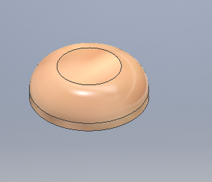
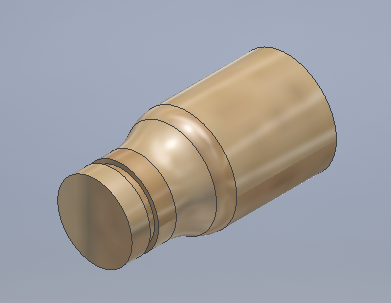
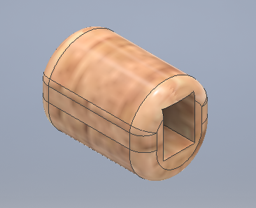
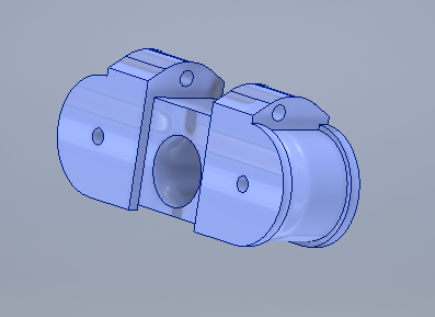
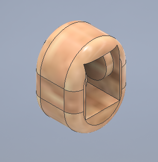
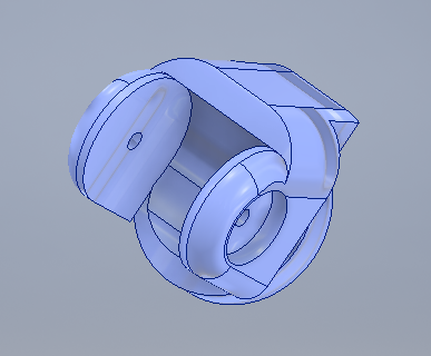
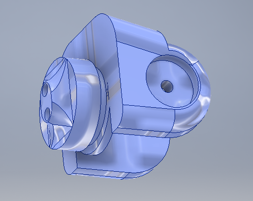
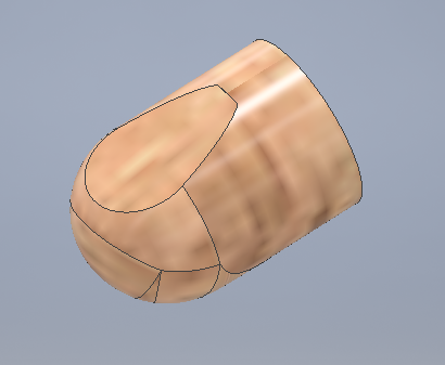
They all still looks like shapeless figurines, but it all makes sense after we assemble the pieces
First of all, the previous parts were scaled just for one finger, and the measures I took were from my own index, so I had to scale all the parts following a ratio I measure with, once again, my own fingers.
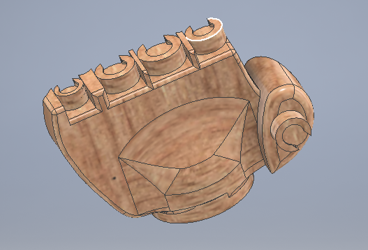
Later on, the palm had to be designed for all the fingers to fit in well. The palm finally looked like this:
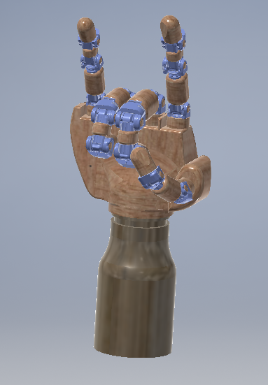
Finally, the assemble and render came to place. The final design looks like this
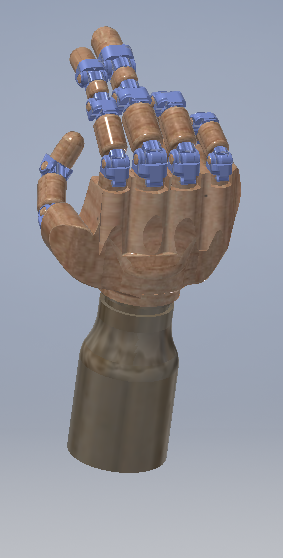
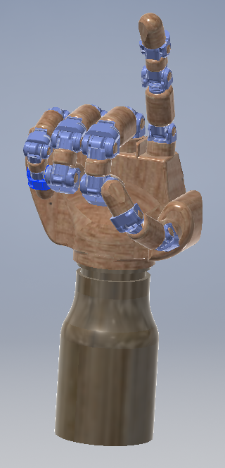
:)
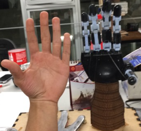
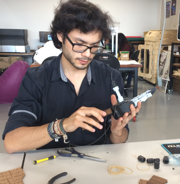
Here's a pic of how it finally got alive
Download zip Inventor files:
Index Finger Middle Finger Pinky Finger Ring Finger Thumb Assembly2) 3D Printing
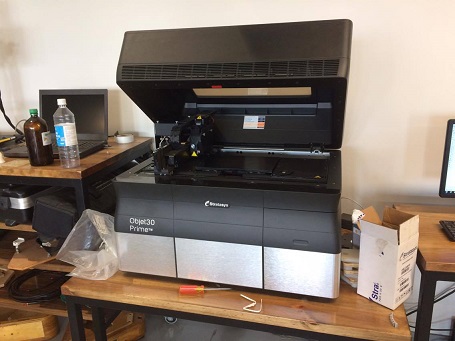
After designing all parts, the manufacture process begins. Luckyly, most parts of the design could be printed using a 3D printer. For functional purposes, I used the Object30 Prime 3D printer from Stratasys because one of the resins it uses was "tango black", a material that has flexible properties when printed.
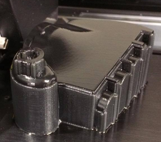
The biggest part to be printed was the palm of the hand. It looked like this when printed
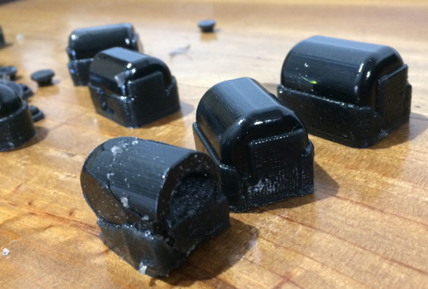
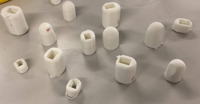
Then, I printed the parts that were meant to have the texture and looks of the "skin" of the hand
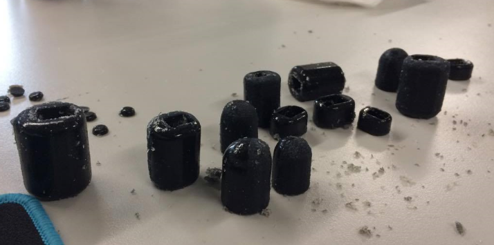
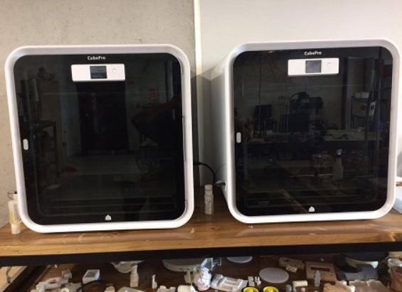
I printer the same parts in ABS using the cube pro 3D printer from 3D Systems so they are rigid enough to act like a positive mould for the future manufacture technique: moulding and casting. It's cheaper and effective !
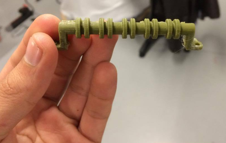
The rest of the parts were printed in the Object30 again, but this time with a rigid resin called "rgd540". This type of resin gives a nice finish and with a high level of details. A Printed finger looked like this
Download zip STL files:
STL files3) Moulding and Casting
As mentioned before, the moulding and casting technique allows to massively reproduce exact pieces of the same mould at a low price, but the main advantage I saw was that it also allows to have pieces with a variety of textures depending on the quantity of the cathalist or the compound we use. As I needed to reproduce flexible yet strong pieces (the bumpers of the hand), I found this technique very appropiate, so I gave it a try.
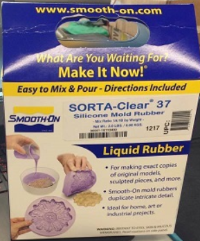
I started chosing the material for the mould. I finally decided for Sorta Clear 37 from Smooth on Inc because it was the only one in stock that was transparent and allowed the pieces to be visible, making the set up easier
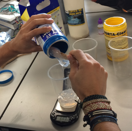
I started, As in week 12, the mixing of A and B
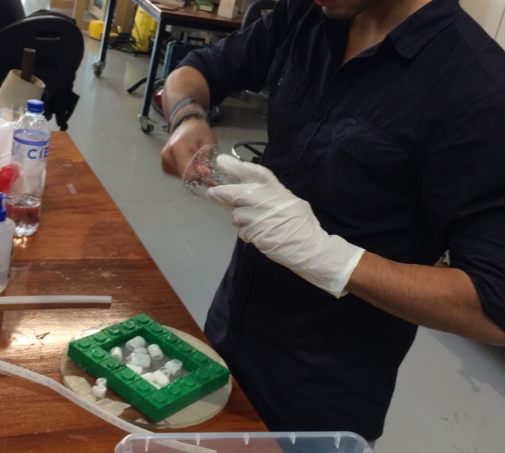
Then, I set up the environment for the moulding
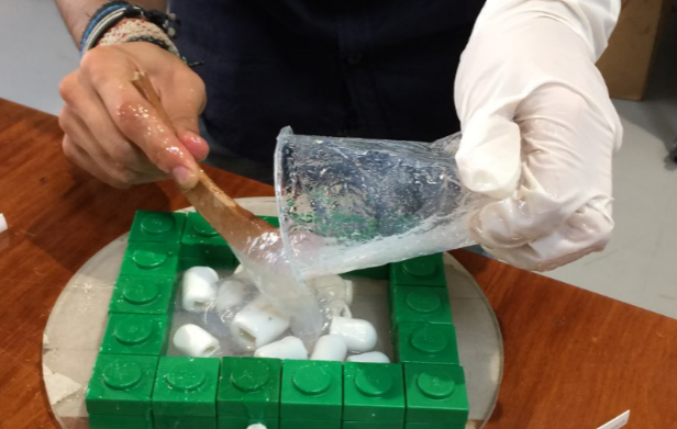
And proceed to the moulding itself
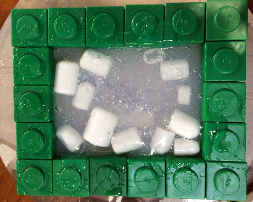
For the casting, I used silicon. It gets rubby, but sturdy; perfect for this purpose.

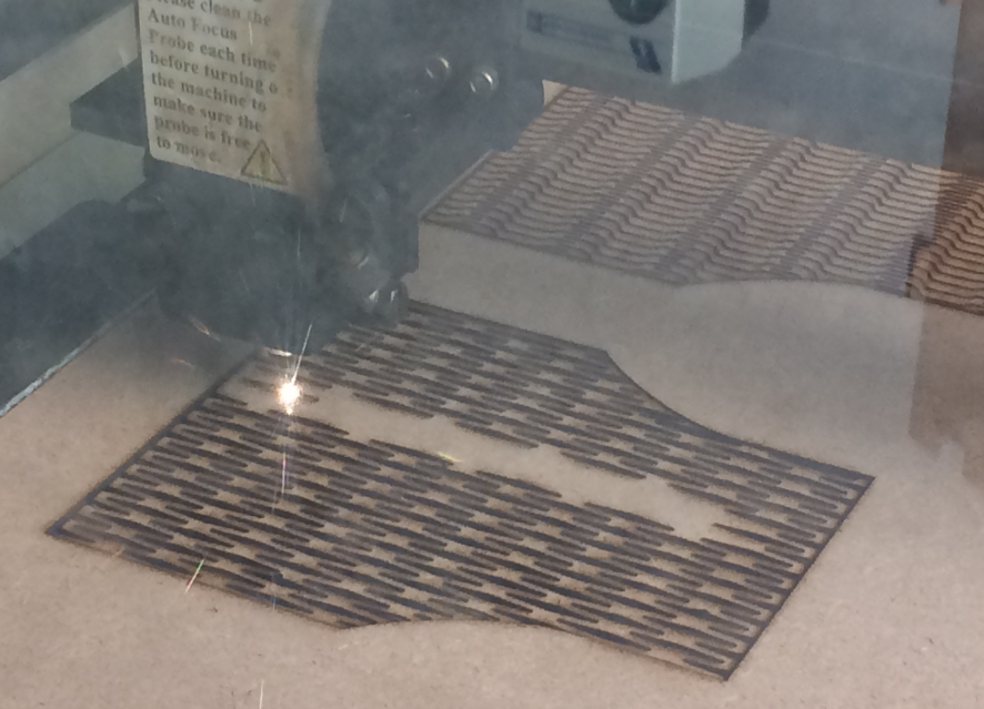
4) Laser Cutting
As one of the requirements for the final project was to include some 2D design, I had to think of how I'd integrate it with my project. I remember having seen a way to, using 2D parametric design, make some curved surfaces. this technique is called "live Hinges" and I decided to give it a try. I decided to make the wrist of the hand using laser cutting. It gives a nice finish and uses only a minimal amount of material.
I learnt a lot of Live Hinges in this Instructable page. If you want to know more about Live Hinges, I strongly recommend This page that actually explains some of the physics involved in this technique and Gregg Fleishman furniture that inspired my design.
I found a compilation of parametric laser cut for live hinges in the web. here are the autocad view for the parametric Kerf designs in Autocad

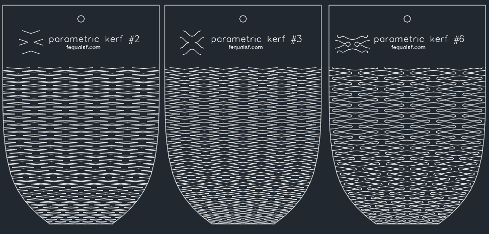
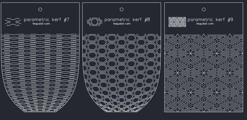
I found out that the design that allows the most bending was the Parametric Kerf #4, so I made the wrist design using that pattern
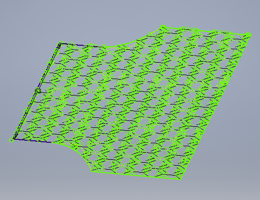
Then, the machining process takes place.
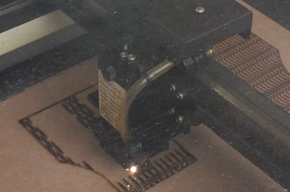
And finally the fire test. It worked !
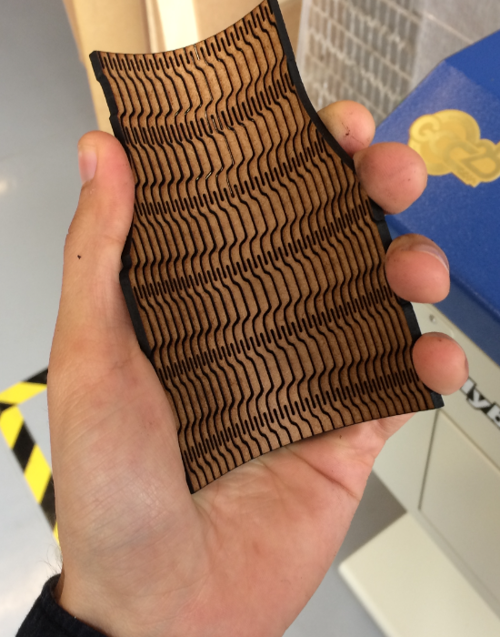
This is how the wrist looked at the end. It fit perfectly and looks beautiful
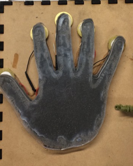
In addition to that, I made a panel using acrylic with the shape of the hand that will act as the sensor panel for the control of the hand
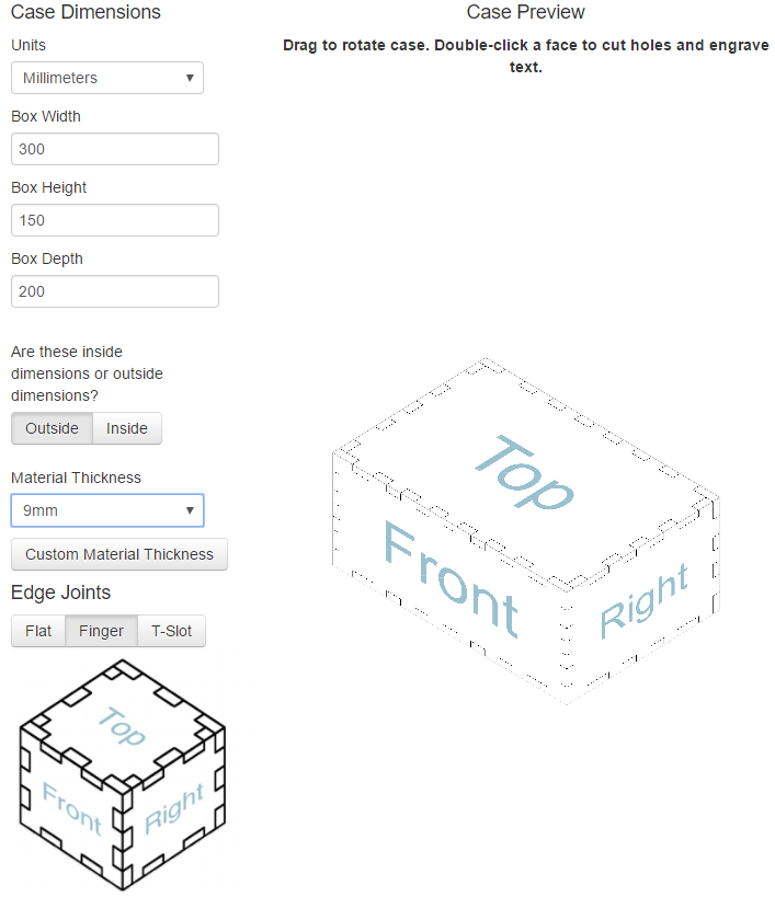
Finally, I made a box that was meant to be both the support of the hand and the case for all the electronic mess
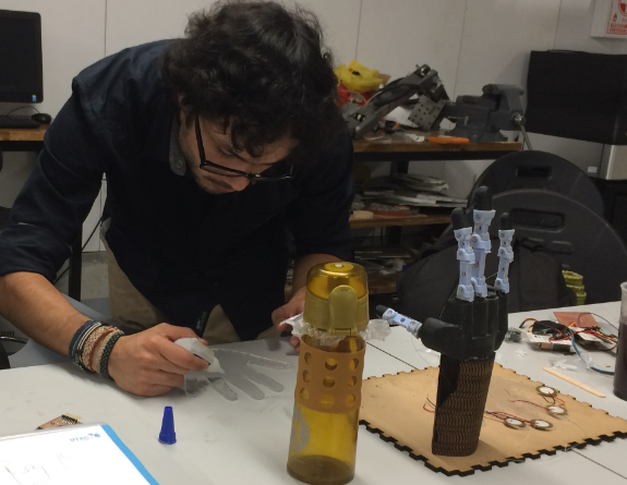
Here it's me integrating all the laser cuts of the project.
Download zip DXF files:
DXF files5) Electronics and programming
Against all odds. This part of my project was very simple to integrate as the logic behind the control system was simple.
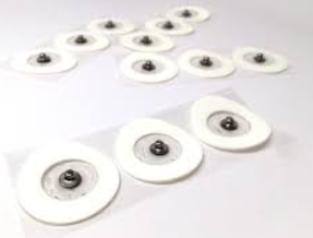
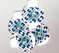
At first instance, the final project was meant to be a prosthetic hand, so the former sensors I meant to use were some EMG electrodes available at any drugstore. Those sensors have the following presentation:
An amplification and filter were needed for the sensors to work properly because they only delivers signals in the order of microvolts. So I followed the instructions from several pagesLike this one
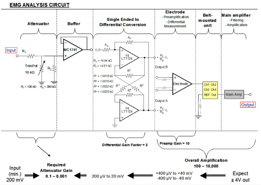
But problems started to appear. The first problem was that after the amplification, the signal were still low that the arduino couldn't even detect a device from its port. And the second problem I found was that the OpAmp needed for most schematics to work weren't available at my country (Perú), and in order to import it from digikey we had to pay a really high price that it wouldn't be cost effective. So I completly change the focus of the project from "prosthetic" to "Robotic" Hand.
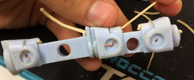
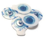
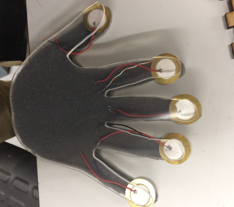
The sensors I used were simple piezoelectrics like this one
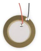
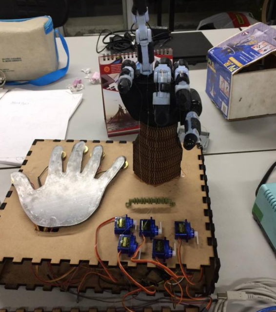
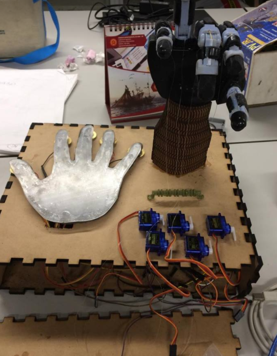
They were located at the tip of each finger below the acrylic panel so it simulates a tactile panel. plus, It looks cool !
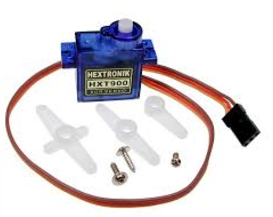
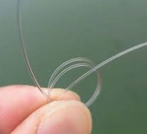
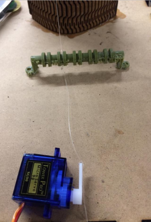
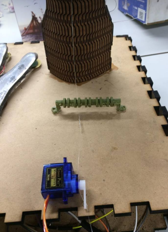
The actuators were meant to be servomotors from the begining. They'd pull the fishing wire attached to each finger and, therefore, pull the tip of the fingers downside contracting them. So I used Simple microservos for this task
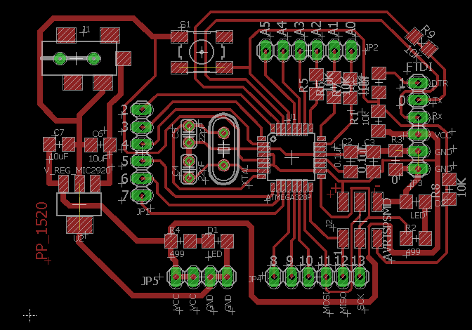
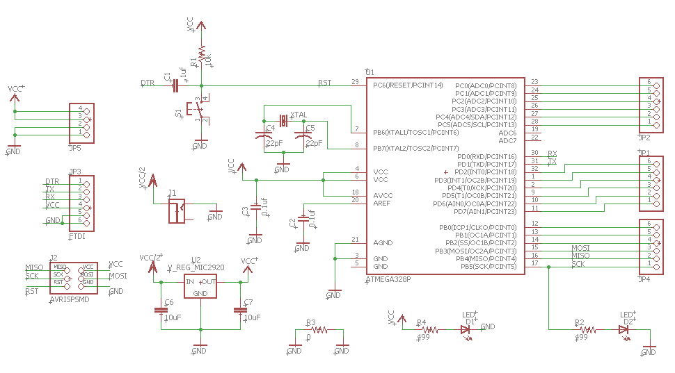
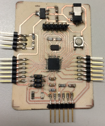
The microcontroller I used was a modified version of the Fabduino with five 10K ohm resistors connected to the piezo pinouts and VCC interconnected. Here are the board and schematic
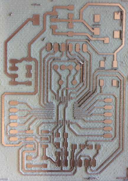
And here's the before and after soldering :)
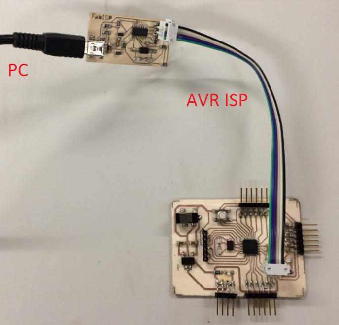
Then the process of burning the bootloader with the ISP took place so we could program it as it were an Arduino UNO
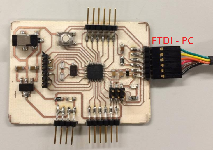
And finally, run the program with the FTDI cable
Here's the code I used
#includeint sensor0 = 0; int sensor1 = 0; int sensor2 = 0; int sensor3 = 0; int sensor4 = 0; Servo servoMotor3; Servo servoMotor5; Servo servoMotor6; Servo servoMotor9; Servo servoMotor10; void setup() { pinMode(A0,INPUT); pinMode(A1,INPUT); pinMode(A2,INPUT); pinMode(A3,INPUT); pinMode(A4,INPUT); Serial.begin(9600); servoMotor3.attach(3); servoMotor5.attach(5); servoMotor6.attach(6); servoMotor9.attach(9); servoMotor10.attach(10); } void loop() { sensor0=analogRead(A0); sensor1=analogRead(A1); sensor2=analogRead(A2); sensor3=analogRead(A3); sensor4=analogRead(A4); //primer dedo if (sensor0 <= 800){ servoMotor3.write(180); } if (sensor0 > 800){ servoMotor3.write(0); } //segundo dedo if (sensor1 <= 800){ servoMotor5.write(180); } if (sensor1 > 800){ servoMotor5.write(0); } //tercer dedo if (sensor2 <= 800){ servoMotor6.write(180); } if (sensor2 > 800){ servoMotor6.write(0); } //cuarto dedo if (sensor3 <= 800){ servoMotor9.write(180); } if (sensor3 > 800){ servoMotor9.write(0); } //quinto dedo if (sensor4 <= 800){ servoMotor10.write(180); } if (sensor4 > 800){ servoMotor10.write(0); } Serial.println(sensor0); }
Download the code:
Arduino CodeDownload EAGLE schematic and board
Schematic Board6) Bill of Materials
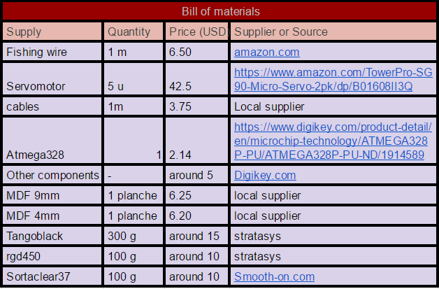
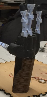
6) Integration
Finally, putting it all together. From the assembly of the 3D printed parts, to the integration of the laser cutting and electronics. Enjoy !
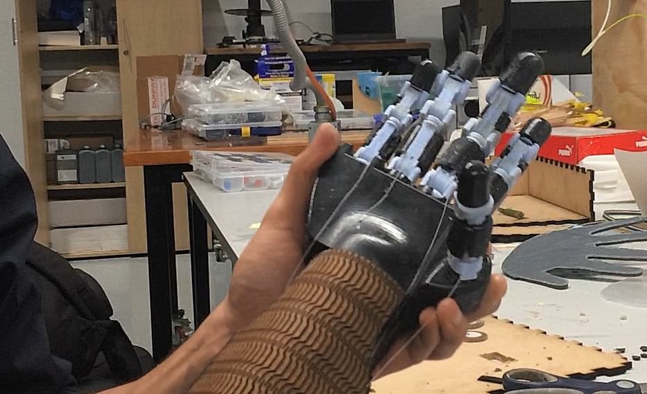
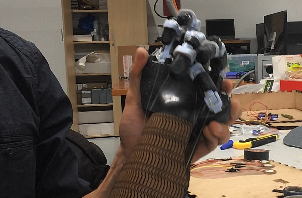
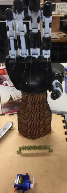
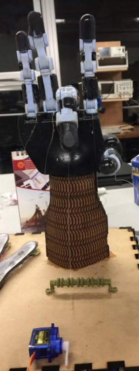
Result. Its alive !