So for week #13 we were assigned to measure something.to add a sensor to a microcontroller board that we have designed and read it.
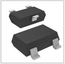
For my assignment I Chose to use a hall effect sensor, because one of its uses is speed detection and am doing a skate board for my final project, so I thought that it would be good idea to use it.
I startred by reading and learning about this sensor because this is the first time for me to deal with a hall effect sensor and I found out that, a Hall effect sensor is a sensor that varies its output voltage in response to a magnetic field.The sensor operates as an analog sensor, directly returning a voltage. With a known magnetic field, its distance from the Hall plate can be determined.
The first I did was looking at the data sheet of this sensor in order for me to work with this sensor.
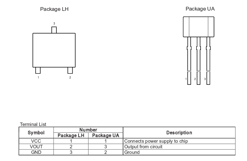
This diagram shows the pins at which I will connect the sensor showing the placement of the the GND,VCC and the signal pin.

from here we can get the output voltage when the sensor is in its quiescent state which is around 2.5v.
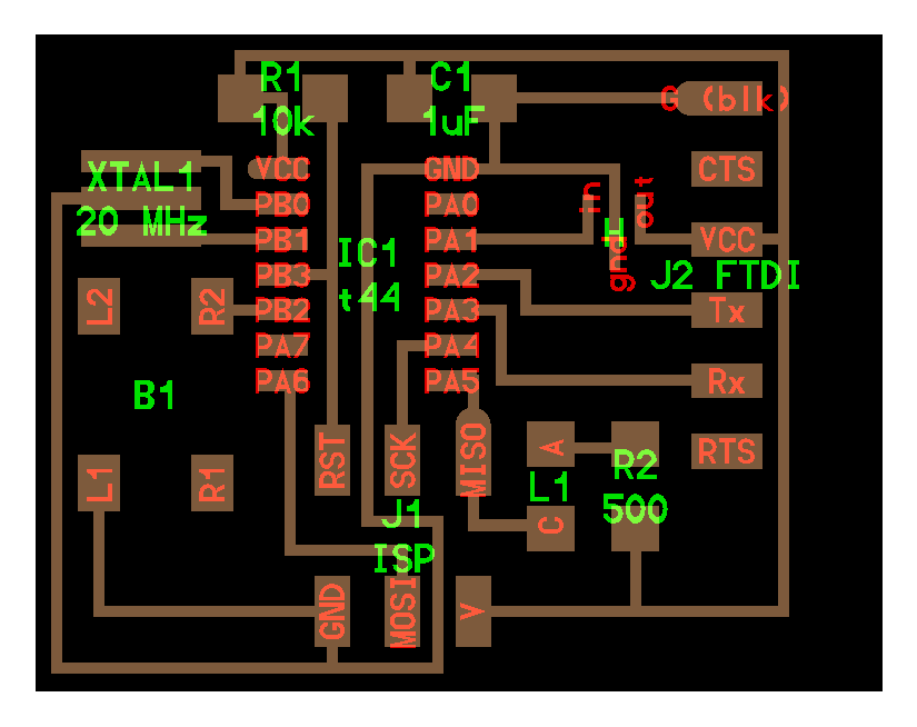
Then I started by adding the sensor to my echo hello-world board from week 6:
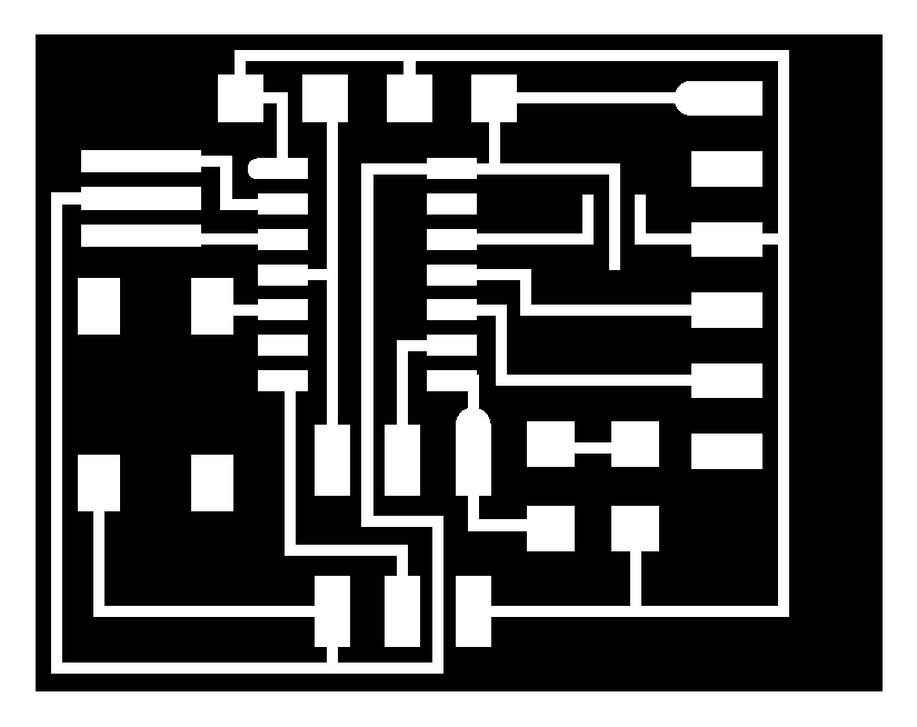
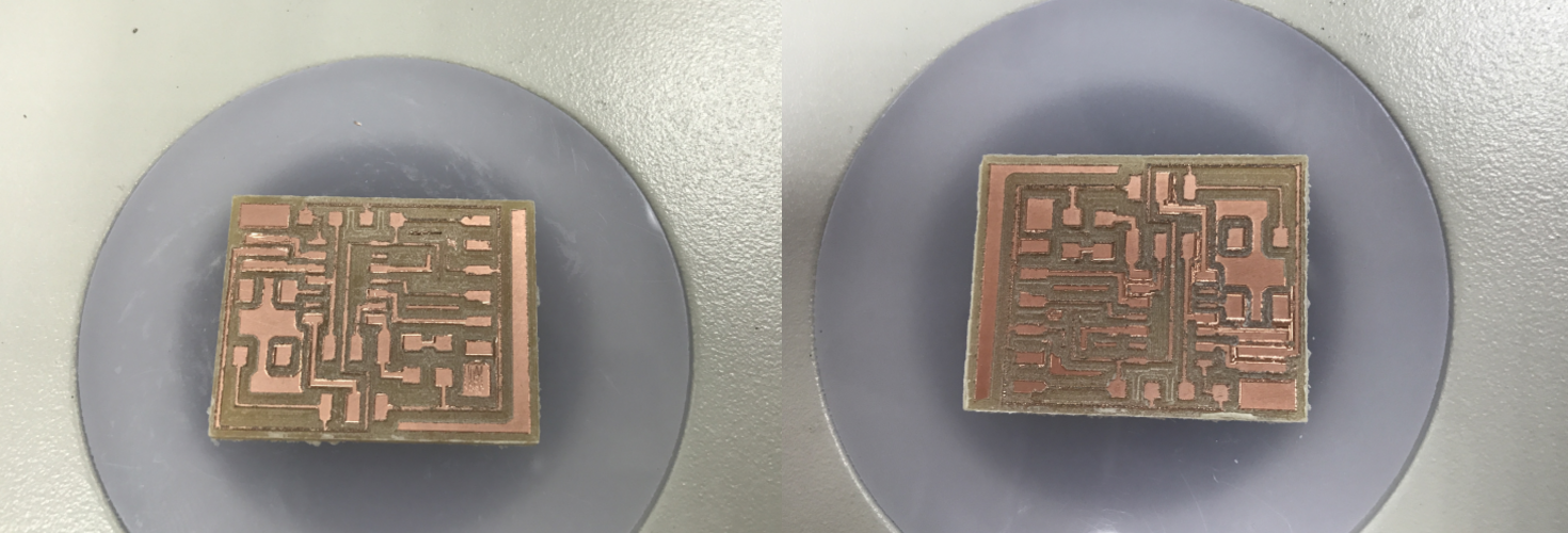
Then I exported the traces and the cutout to mill the board:

Then I milled the board using the SRM-20, But the problem was that the last milling bit broke so I had to mill using the broken bit and remove the linked traces with a sharp knife : 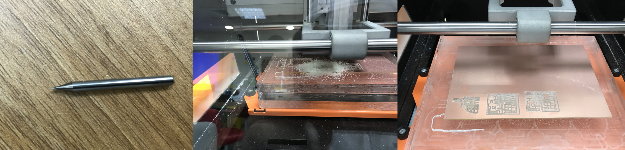
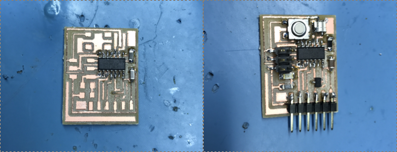
Then I stuffed my board with the components and moved to programming it:
The first thing I did was to use the sensor as digital device, so I just programmed it with the LED, and once the magnet pass near the sensor the LED will light up:
When I was done with using the sensor as a digital device, now it was time to use the sensor as a analog device which is much harder than the digital part, because I had to use ADC (Analog to digital Converter) which is something that am not familiar with, I didnt mention this earlier but the reason I connected the sensor to PORTA because PORTA have ADC, while in PORTB doesnt have, but I as we all know in order to learn you have to get out of your comfort zone. So the first thing was to go to the ATtiny44 datasheet to be able to configure the ADC.To Enable the ADC I used this command ADCSRA |= (1 << ADEN); which is done by writing to the ADC Control and Status Register A ADCSRA. Then to set up the prescaler used this command ADCSRA |= (1 << ADPS2) | (1 << ADPS1) | (1 << ADPS0);
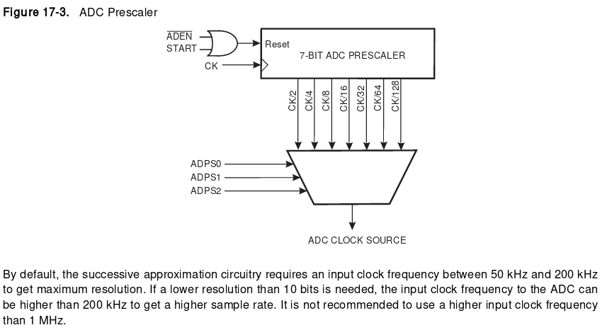
As you can see from tthe datasheet, the ADC requires an input clock frequency between 50 kHz and 200 kHz to get maximum resolution. I used 128 and the 8 MHz clock. so the ADC will be running at 8MHz/128 = 62,500 Hz or 62.5KHz. For setting the reference voltage I used this command ADMUX |= (0 << REFS2) | (0 << REFS1) | (0 << REFS0) this will set the reference voltage to VCC.it and can be set by writing to the ADC Multiplexer Selection Register ADMUX.
Then in the while loop to begin the conversion I used ADCSRA |= (1 << ADSC); writing 1 to the ADC Start Conversion ADSC bit will start the ADC conversion process. then wait for the conversion process to finish while (ADCSRA & (1 << ADSC)) , after that I just used the if function to turn the led off if it senses a magnetic field and on if there is no field. the video below shows the sensor in action:
Previous Week |-----------| Next Week