This week talks about output devices, and in this weeks lecture we were introduced to a variety of output devices, like LEDs, DC motors, LCDs, stepper motors and speakers. And for this weeks assignment we have to add an output device to a microcontroller board that we have designed and program it to do something.
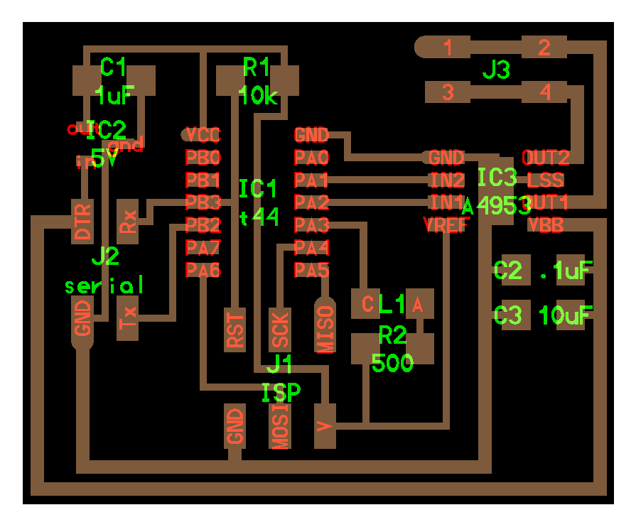
So as we have each week to try to embedd the skills that we learn into our final project, I chose to work with a DC motor as my output device as am doing a electric skateboard for my final project. I started by modifing Neil's DC motor board, the first I did was changing the power header and adding a Tx and Rx in order to Communicate with the board from another board because I will need that later in my final project, then I added an LED to PA3.
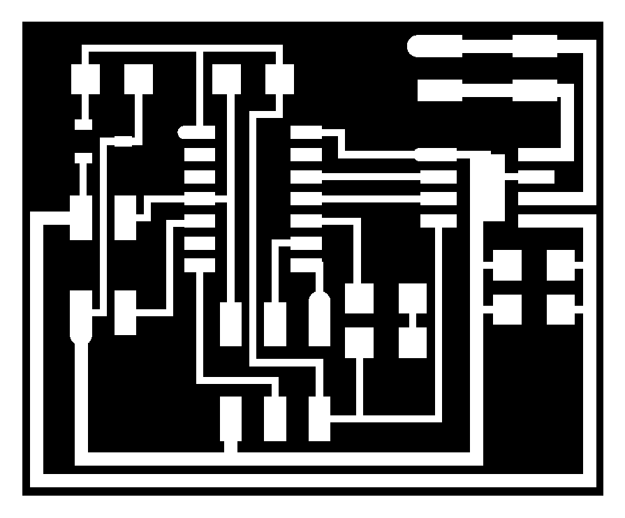
Then it was time to mill and stuff the new board, so I exported the traces and the outline png images and uploaded them to fabmodules to start milling.

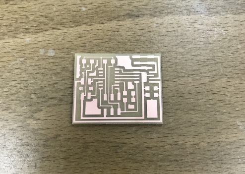
After that I milled the board using our Roland SRM-20.
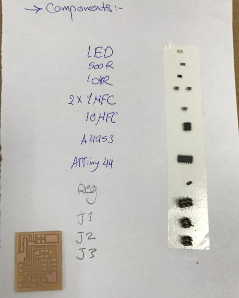
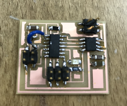
Now it was time to stuff the board, so I prepared all the components and started soldering them.

Then I discoverd that I did a really stupid mistake, so instead of connecting Rx to PB1 I connected it to PB3 which is the RESET, so after I finished soldering I had to make some adjusments to the board to fix the problem, I used a jumper wire to connect Rx to PB1 and cut the trace from PB3 using a sharp knife. Then I corrected the kokopelli file to attache it later.
Now it was time to program the board and test the motor.So I took Neil's code for the DC motor from the archive and modified it a little bit to make the motor rotate continuously, I dont know why Neil like to complicate things, like when I looked at the code for the first time I didnt understand anything at all, but after spending a lot of time finally I understood the whole thing, and now I will explain what I did to the code plus why Neil likes to complicate things. So lets start with this:
#define set(port,pin) (port |= pin) // set port pin
#define bridge_port PORTA // H-bridge port
#define IN1 (1 << PA2) // IN1
set(bridge_port, IN1);
So what Neil did was to create a function called set() which have two parameters port and pin, what this function do is set the pin to high in the defined port, and also he did the same thing with the function clear() which set the pin to low, but instead of typing all of these Neil could just type the following and it will do the same:
PORTA |= (1<< PA2);
Which is the command used to set the pin to high also to make the DC motor move for example clockwise continuously. what I did was to take everything out of the while loop and keep this command, which set the pin to high all the time:
set(bridge_port, IN1);
I did a more advanced programming in the final project using PWM.
Previous Week |-----------| Next Week