In this week, we learned about how to make our own Printed Circuit Board to power the electronics we will design. A Printed Circuit board is a neatly designed board, on which we can fix our electronic components. The PCBs are made on a copper clad sheet, which are like copper coated on a non-conducting material. We can selectively remove the copper to create the traces (path ways). There are many ways to make a PCB which include Milling, etching etc. We will be focusing on the Milling process.
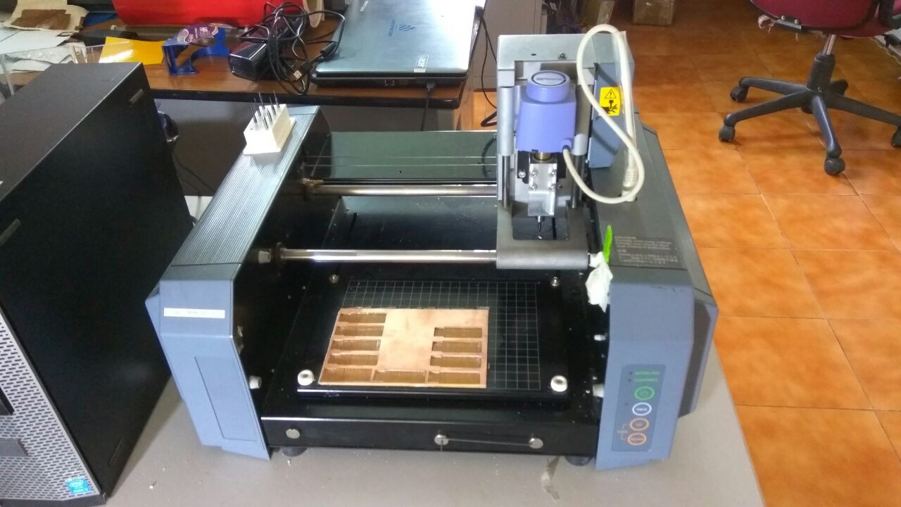
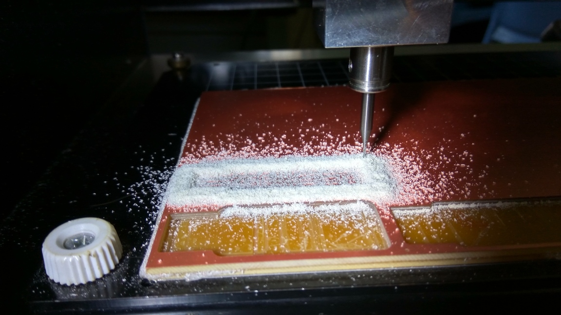
We use the Modella MDX 20 to machine our PCB. Modella is a Desktop milling machine that is capable of milling wood, wax, MDX,and circuit board blanks. It is compatible with most of the 2D and 3D CAD softwares. It has a small bed which moves in the Y-axis, a Tool head which moves in the X-axis and the end effector which moves in the Z-axis. It supports many milling bits and is versatile. The machine itself has a tiny foot print and can be placed on a table.
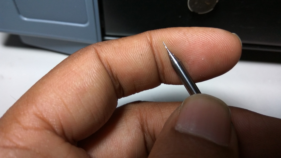
We use the fab modules to give commands to the Modella and run the cutting program. This machine is very delicate and the bits are very fragile, take care in removing the milling cutters and correcting the zero setting.
Modella MDX 20 behaves like an ordinary 3-Axis CNC machines, Each axis is driven by a stepper motor and the cutting program tells the machine where to go by giving coordinates to the machine in real time.
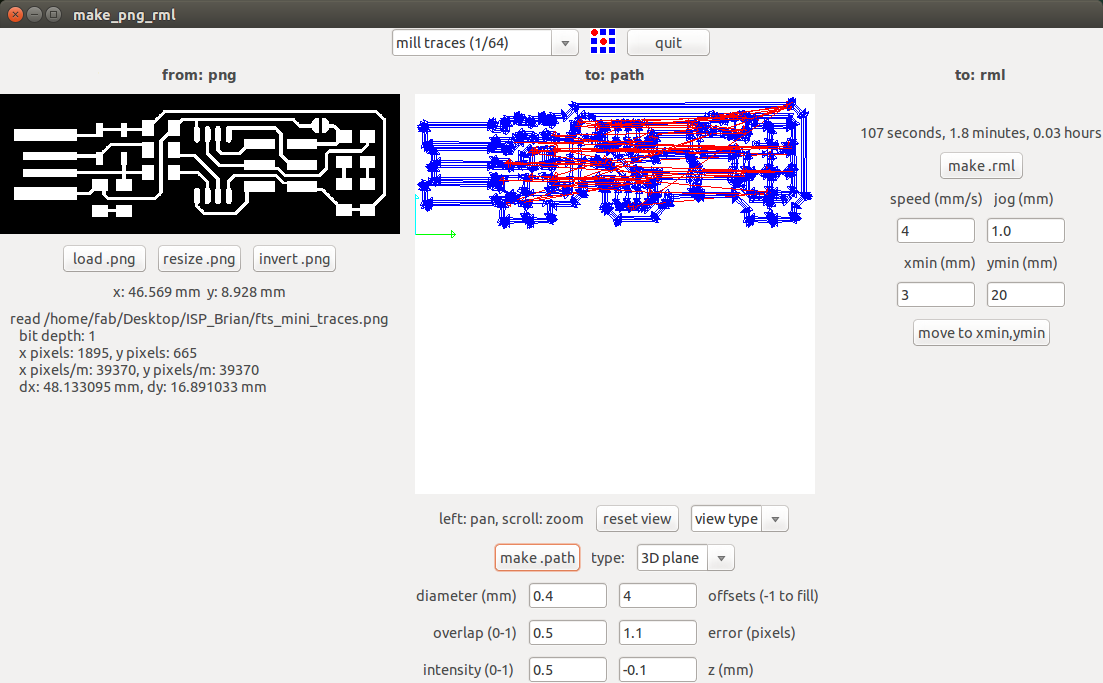
What the software does is that it converts the .png image we give into a series of tool paths, these tool paths are defined by their coordinates. The .png image is a black and white layout of the board, and the black portions will be milled and the white portion is where the copper will be left.
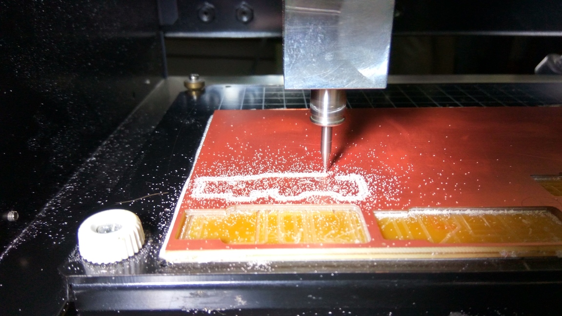
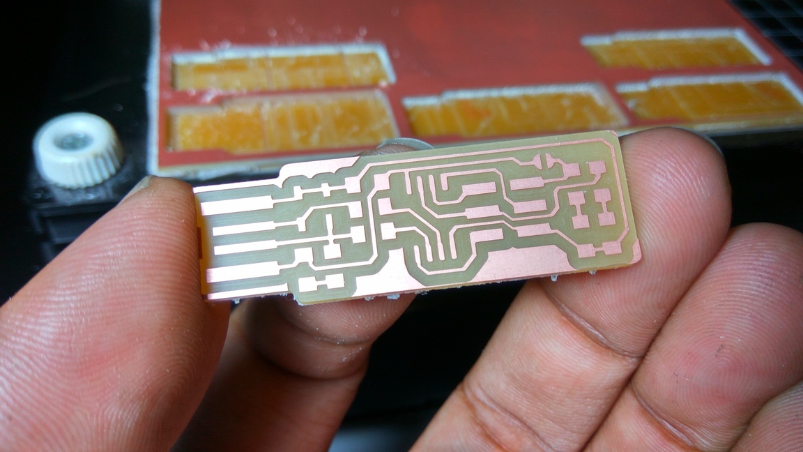
We have two milling processes in cutting a PCB, The first one is milling the traces to get the circuit board pattern, and the second is cutting out the board from the base material.
For milling traces, we use the 1/64th inch (0.4mm) bit and for cutting 1/32th (0.8mm) inch bit.
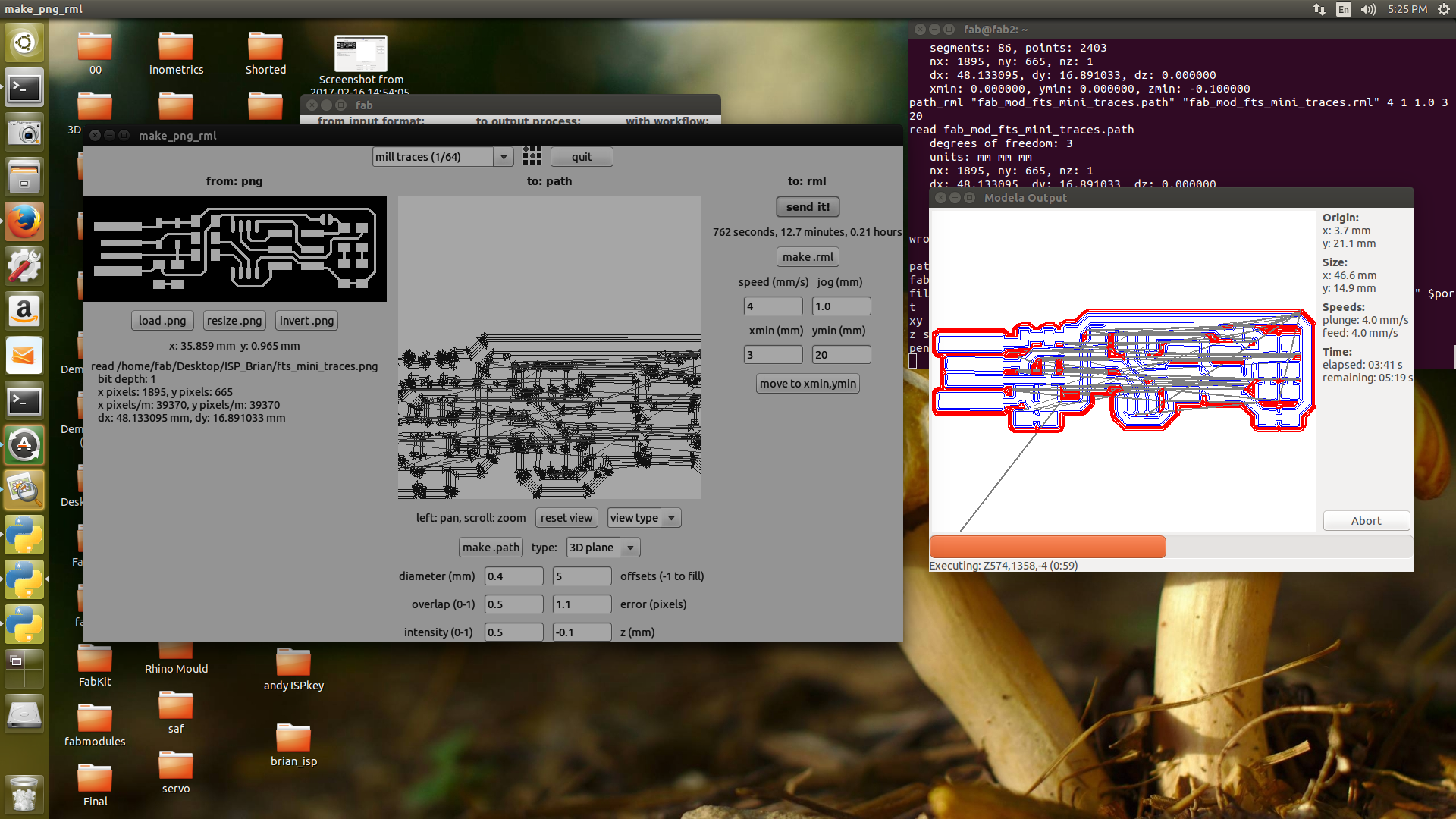
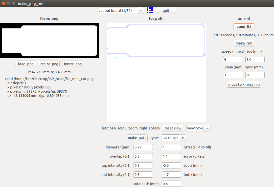
Got to the terminal and run fab Now the fab module will open and the select the input format to .png and select the output you want depending on your machine (modlella MDX 20).
On the top menu select the process you want to use. For milling traces, select the milltraces(1/64) option. Now click load .png to load your traces file and click make path Now you can see the path the tool is going to move through. You can change the setting, I'm leaving it in the defaults. Now if you click make.rml and click send rml
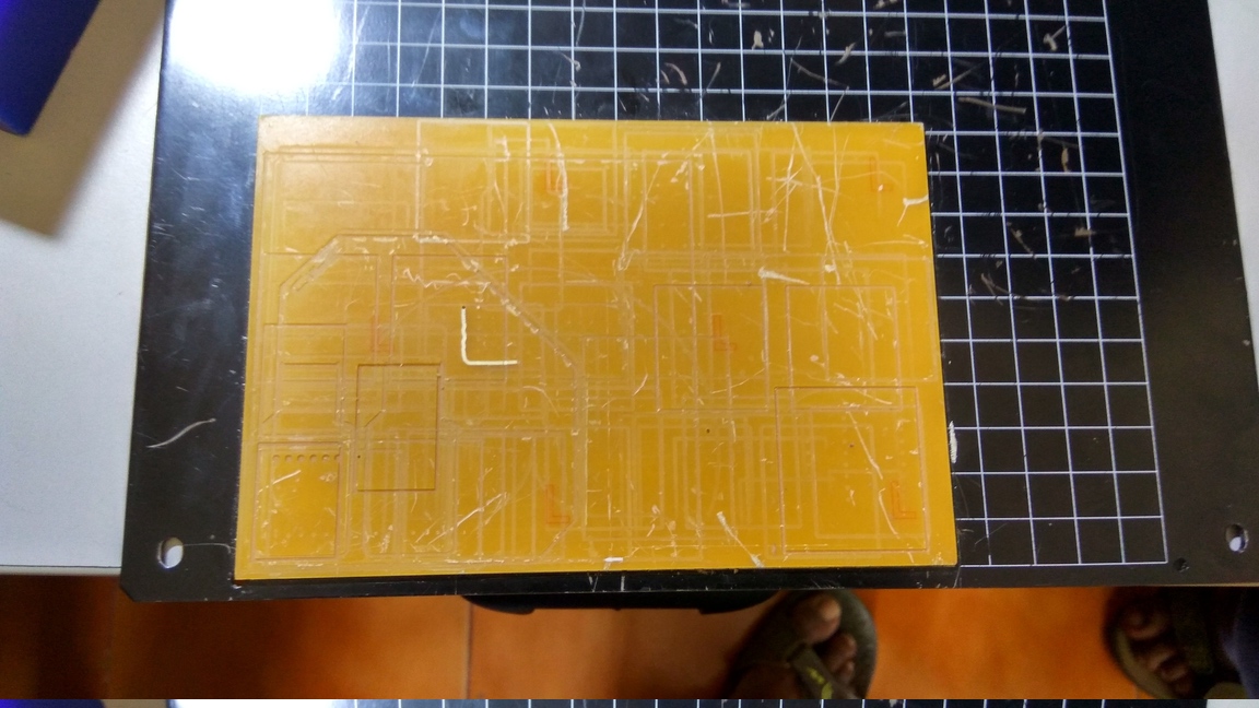
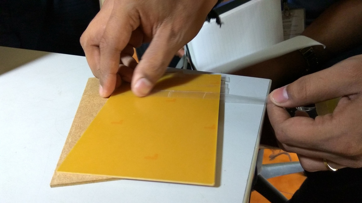
You need to place the PCB to be cut on top of some sacrificial material. You can use a second PCB as sacrificial material. The sacrificial board is so that when you cut all the way through the top one, it won't damage the bit or the machine’s table.
Affix the sacrificial board to the mill’s metal table with flat 2-sided tape. Make sure no air bubbles are present.
The 0,0 coordinate of this machine is at the bottom left corner of the grid design on the metal plate.
Fix the PCB you want to cut firmly on the sacrificial layer using the double sided sticky tape.
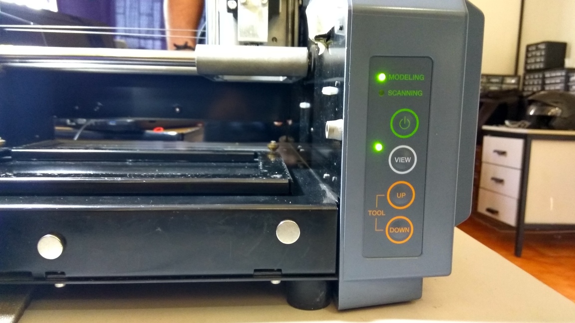
Click view and the table should come out and the head will move to the far right, now load the bit you want to use, for milling traces, we use the 1/64th inch bit and for cutting 1/32th inch bit. Now insert the bit and use the Allen key to tighten the screw. Make sure it is tight on both sides.
Click the view mode again and the machine will move to the (0,0) position. Now click the “move to Xmin and Ymin” button to move the milling head to a blank spot on the material.
Slowly lower the tool head by pressing the down button until the tool is just above the material. Loosen the screw and let the tool touch the material, and tighten it until its is snug. This will be your zero setting.
Now double check your speed and depth settings and the tool position. Now you can start cutting.
I'm writing the precautions from all the mistakes me and my friends made.
Always double check your cutting speed and depth before cutting.
Never click move to Xmin and Ymin, when you don’t know the z value. The tool might hit the bed and break.
When setting the zero on Z-axis, tighten both screws of the tool holder properly. We broke one bit because the tool was not fit correctly, it slipped, dug into the board and broke.
Be careful when clicking move to Xmin and Ymin after setting zero position on Z-axis, If there is some machine error, the tool will hit the bed and break.
Never touch the Up and Down button when changing the tool.
When changing the tool, put a sponge bed below it so that it does not fall and hit the bed and break.
Always remember your Xmin and Ymin values so that in case the power goes out you can resume from the starting position.
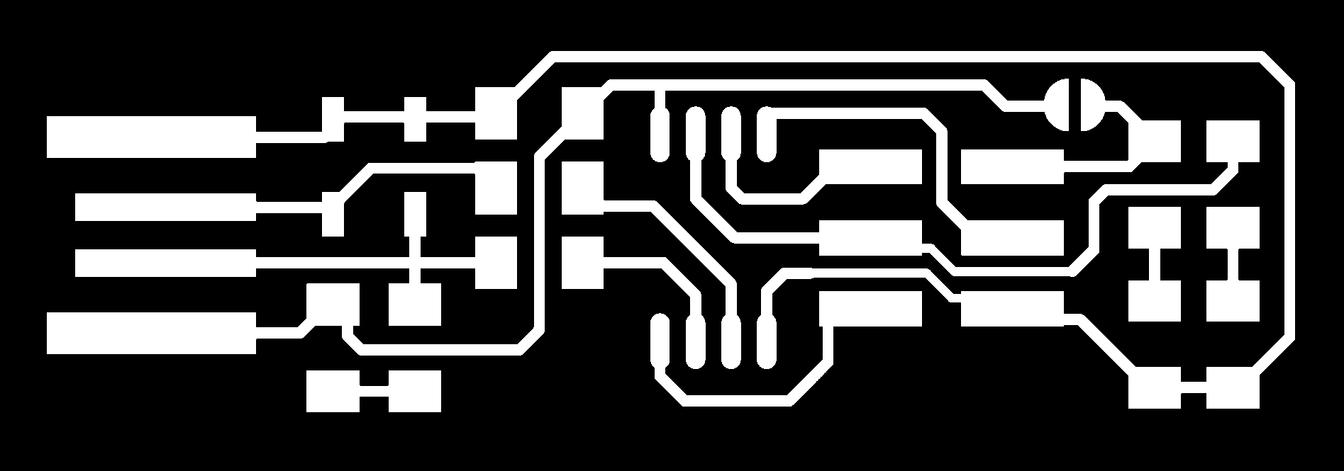

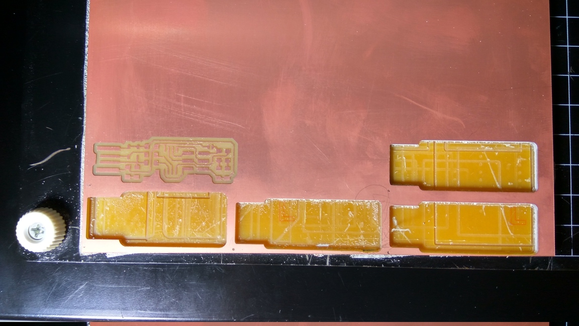
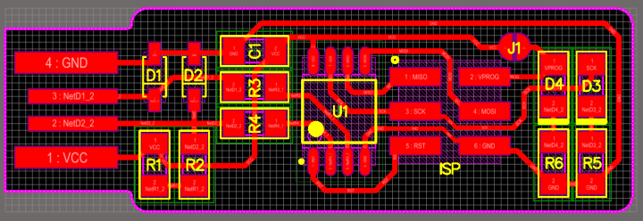
I decided to use the FabTinyISP for this week’s assignment. I would love to give a detailed explanation on why I chose this board over the other ones on a deep electronics level, but I really don’t know. The real reason is that this board had a simple layout, the fewest components, plus it has LEDs. That make debugging a bit easier for a complete beginner. Hence Brian it is.
Download the traces and the outline cutout image files from the website and load them on the fabmodule. Fix the copper clad board on top of a sacrificial material using double sided sticky tape. Move the tool to an empty space on the board and set the Xmin and Ymin of the machine.
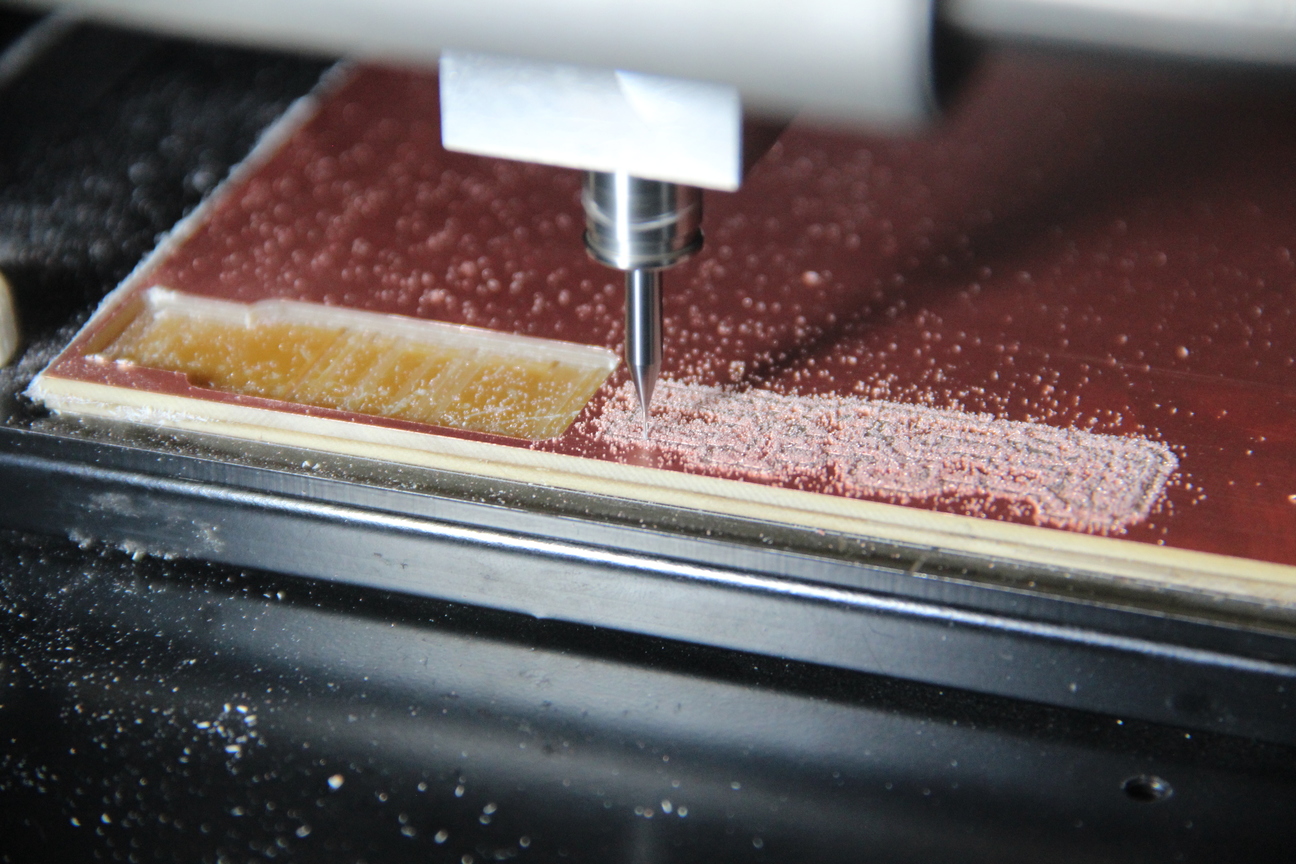
After slowly bringing the Z- Axis down and putting the 1/64th inch bit on the tool holder, I set the zero of Z-Axis by letting the tool touch the board and tightening it in place. Ensure that both the screws are tight.
Once the zero is set then, go to the fabmodule and load the .png file and make rml then send it to the machine.
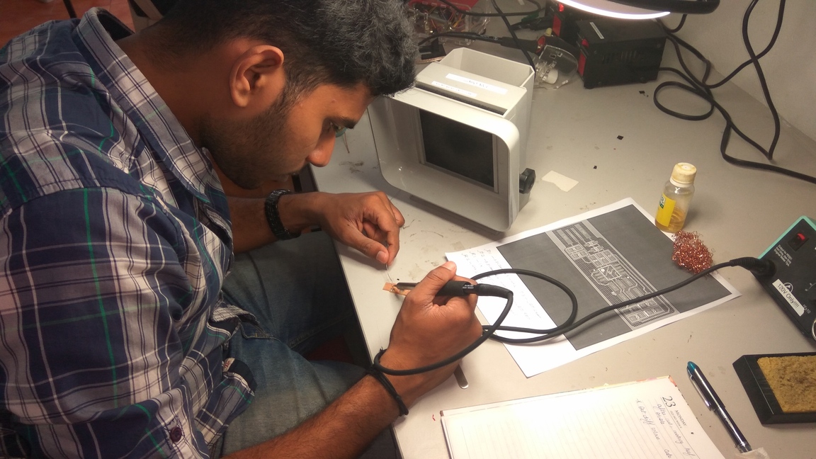
I have limited experience with soldering components and this is the first time I’m working with SMD components, they are so incredibly tiny. First begin by soldering the ATtiny on the board, as this is the most difficult part. Orient the IC using the small dot provided on the body. Using the schematic from the webpage, I aligned and soldered the IC on the board. When Soldering put some flux on top of the board so that the solder will stick properly. Similarly I aligned and placed the components on the board as per the layout.
Important: Some components like Diodes have polarity, always ensure that they are properly oriented so that the components will not be damaged, when you plug it into the laptop.
How to solder SMD components
I was finding it difficult to solder these components until our instructors showed us a method. It goes like this, first put a small amount of solder where you are going to fix your component. Next correctly place the component by holding with the tweezers with your left hand. Now using your right hand bring the soldering iron close to the leg and touch it until the solder melts and it forms a joint. Wait a couple of seconds so that the joint will cool, let go of the part and now it will be fixed securely.
Now take the solder in your left hand and the iron in your right hand, slowly heat the remaining leg of the component by touching it with the iron and simultaneously touch it with the solder. The solder will melt into the joint and let it cool for a few seconds and the joint will be formed.
Repeat the steps for accurate soldering. Adding some flux will help the solder stick to the board properly.
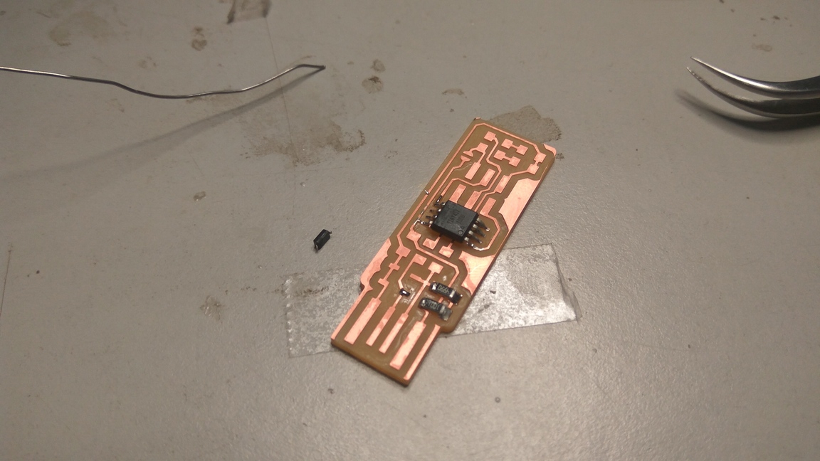
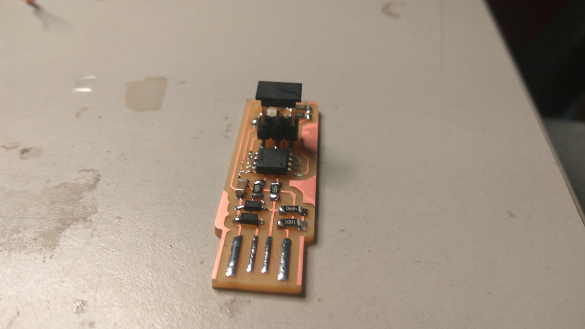
Finished soldering the Attiny onto the board.
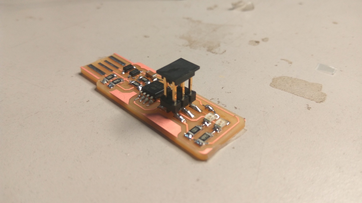
Using the method, my instructor told me I was able to finish my soldering. The board looks good and I'm pleased with the result.
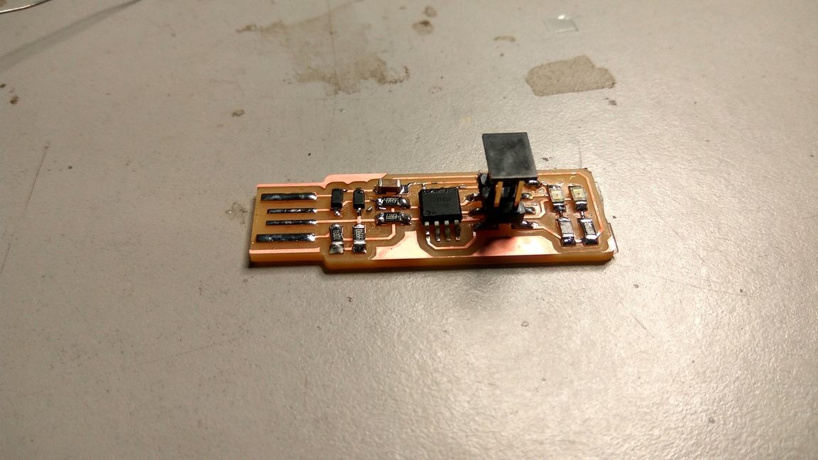
It was an awesome experience to make a circuit board, I feel a lot more possibilities have opened up to me now.
Important: Don’t breath in the fumes produced when soldering. Lead is what caused the decline of the Roman Empire, after the romans used it to line their Aqueducts. Trust me you don’t want to breathe it in. Use a proper exhaust fan when soldering and always solder in well ventilated environments.
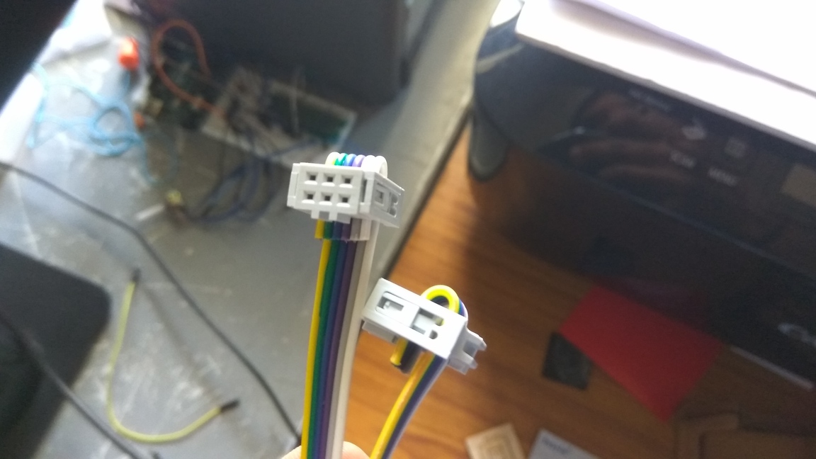
We need to make a cable to connect our programmer to the board we are trying to program. This step is fairly easy.

Cut the data cable in an appropriate size and take two female ISP headers and insert them on both ends and press them into place.
Once you finish soldering the components, It is time to test the connections and program the board. Look carefully at the board to see if all the connections are proper and that no components are sticking into the air. Double check the components and their orientations against the schematic to ensure that the parts are placed in their proper positions. If any components are loose or misplaced, de-solder them and put them in their correct places.
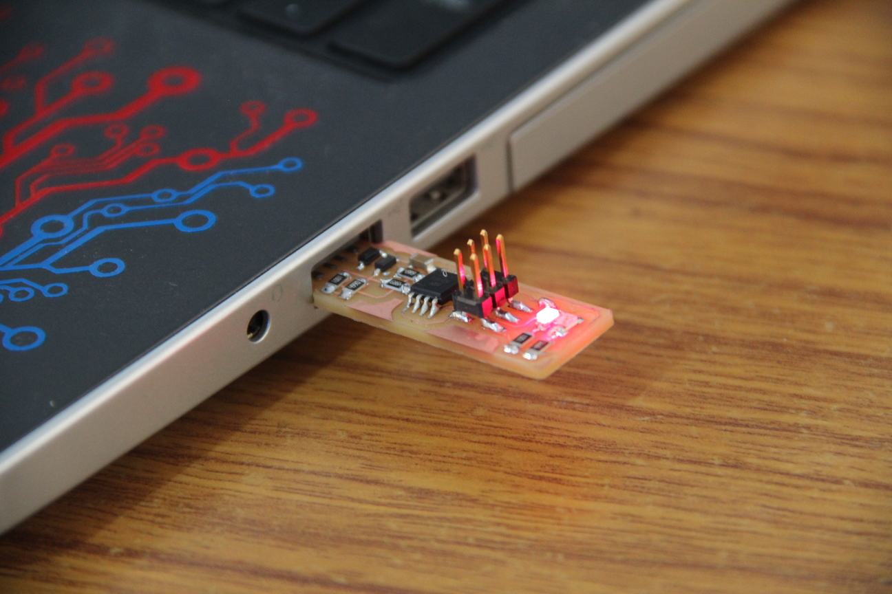
If everything checks out, proceed to plug it into the USB port of your laptop. If the red LED lights up, you’re good to go, if not use the multi-meter to check the continuity of the circuit connections. Thankfully, mine lit up in my first attempt, I was lucky. The next step is programming the chip with the right firmware.
Before you can build and program the firmware onto your board, you need to set up your development environment.
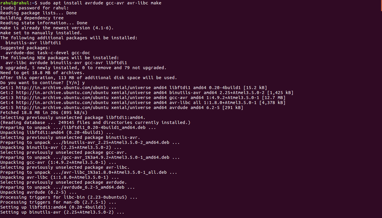
For Ubuntu and other Debian-based distributions, enter the following command, followed by your password when prompted:
sudo apt install avrdude gcc-avr avr-libc make
Download the firmware source code and extract the zip file (on Linux, unzip fts_firmware_bdm_v1.zip).
Open the terminal and go to the directory by using the ‘cd’ command.
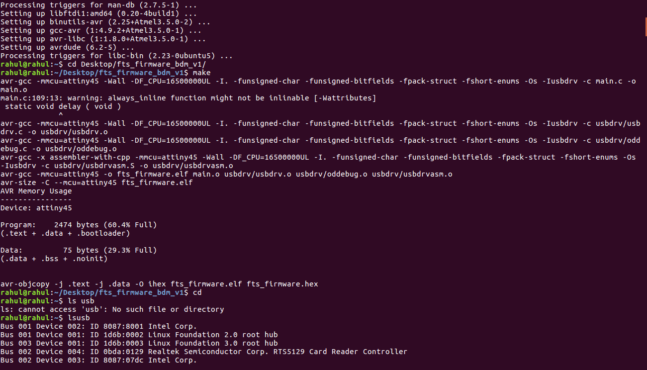
Once in the directory type ‘make’and click enter. This will build the .hex file that will get programmed onto the ATtiny45. When the command completes, you should now have a file called fts_firmware.hex.
The make file of the firmware assumes that you are going to use a programmer in the usbtiny category (another fab ISP). If you're using a different programmer, first figure out what avrdude (the programming software) calls it.
Edit the file called Makefile. It is important to use a text editor intended for programmers. Near the top of the file, find the line that says:
PROGRAMMER ?= usbtiny
and change usbtiny to whatever programmer you're using.
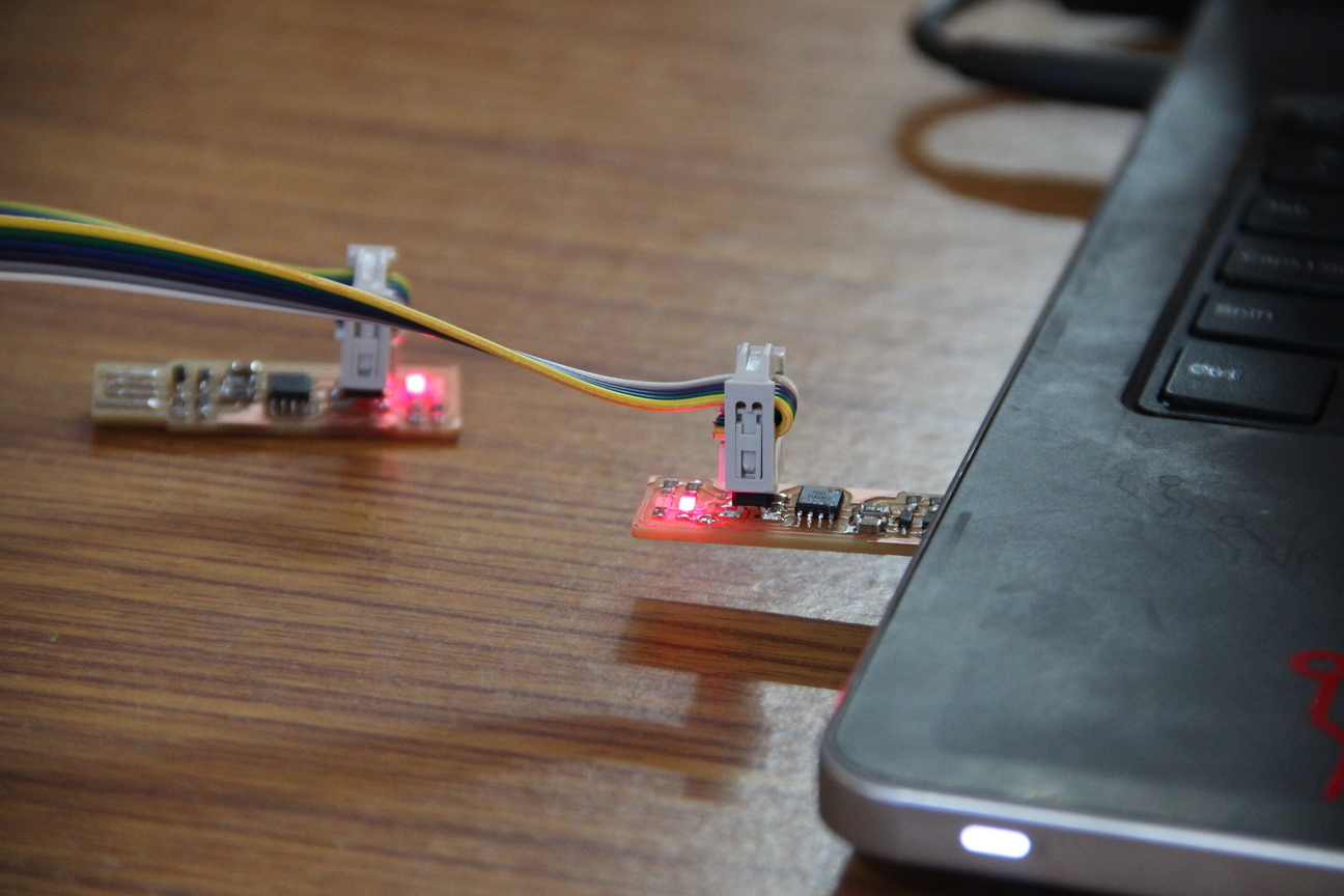
Plug the board into a USB port. USB2.0 is preferred over 3.0 if you have one, and use an extension cable so that you do not put strain on your board especially if your port is upside down. If you installed the red LED, it should be lit up now. If not, check the solder jumper and make sure that it is bridged. If your computer complains about a USB device drawing too much power, unplug the board and check for shorts.
Connect the programmer to the ISP header on your board. Note that there are two different orientations in which you can connect the cable; it is imporatant that you get pin 1 in the right place. Pin 1 is the MISO pin and it should be connected to the MISO pin of the board you are programming.
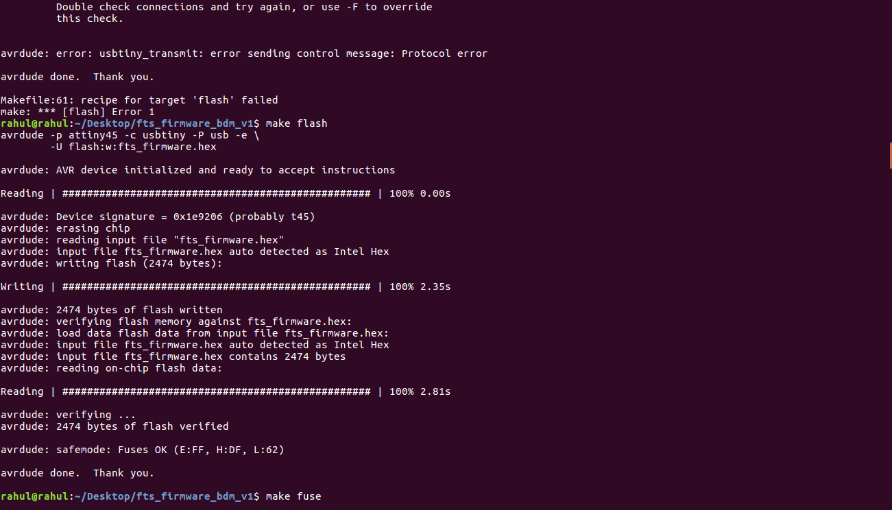
Go to terminal and run the command ‘make flash’. This will erase the target chip and program its flash memory with the contents of the .hex file you built before. You should see several progress bars while avrdude erases, programs, and verifies the chip.
If something went wrong, check:
that the programmer is connected correctly and pin 1 on the connector matches up to pin 1 on the board
that your board is well-seated in the USB port
that the ATtiny45 is installed in the correct orientation
that your soldering looks okay on the ATtiny45 and ISP header (note that shorts can happen where the traces run underneath the connector)
Detailed debugging steps are provided in the FabTinyISP documentation page.
Once you've successfully programmed the flash memory, it's time to set the configuration fuses. We'll do this in stages:
First, we'll set the fuses that control where the microcontroller gets its clock source from. This will allow us to check that the board works as a USB device, but it won't yet be able to program other boards.
Only after confirming that USB works, we'll set the fuse that disables the reset pin and turns it into a regular GPIO pin. This will let the chip use the reset pin to program other boards, but will disable the ability for this chip to be programmed again.
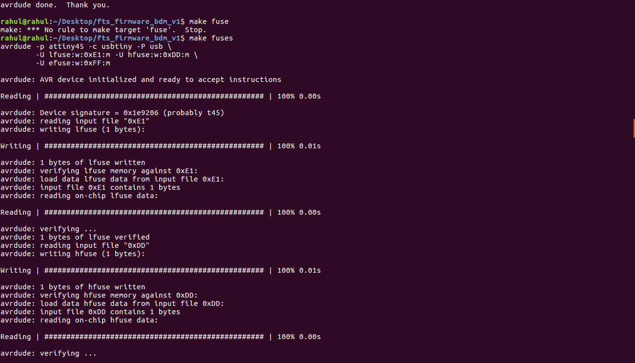
Go to the terminal and run the make fuses command. This will set up all of the fuses except the one that disables the reset pin.
Now we’ll check to make sure that the USB on your board works. Unplug your board from the USBp port and disconnect it from the programmer. Now plug it back directly into the USB port of your laptop. Make sure the programmer you used to program your board is disconnected from the device.
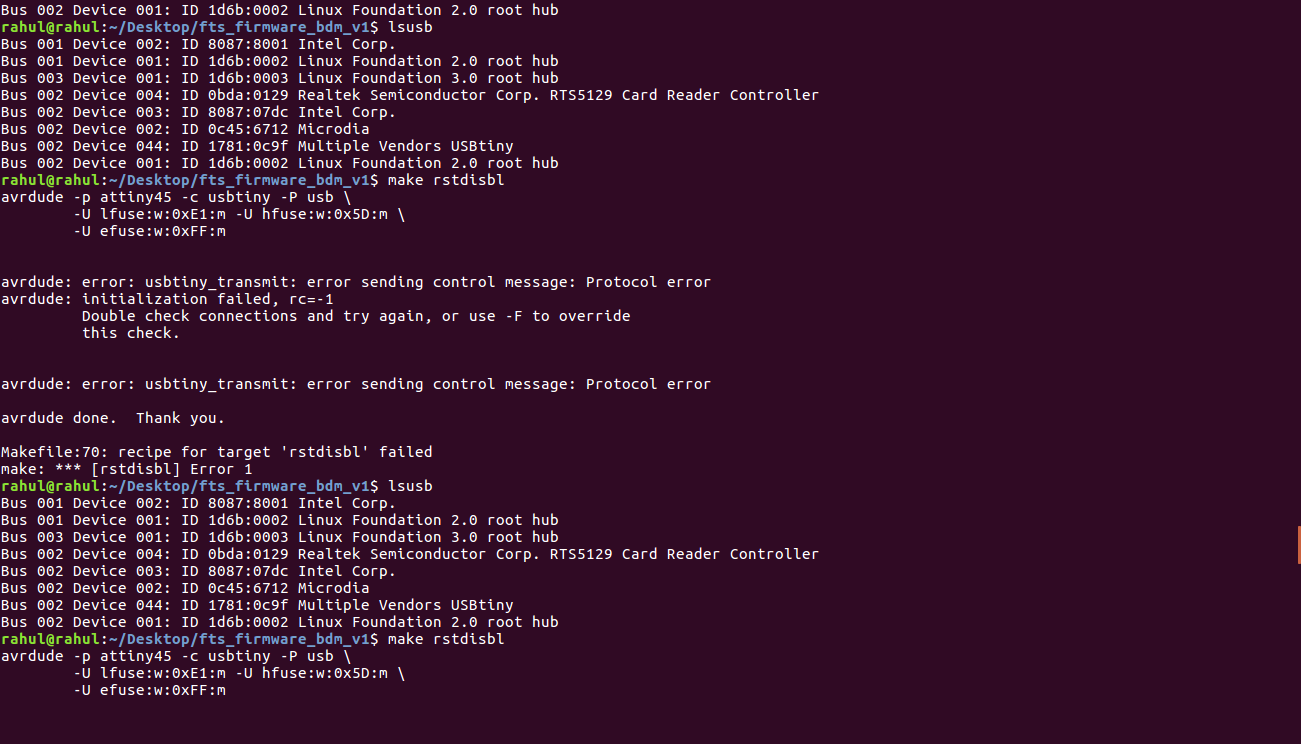
In Linux, type lsusb in the terminal, which will list USB devices. If you see a "Multiple Vendors USBtiny" device, then the programming has worked. If it didn't, the dmesg command might provide more info on what went wrong. Most probably it will be a bad connection between the board and the Port. Look up more debugging steps in the FabTinyISP Documentation page.
If everything checks out its time to Blow the Reset Fuse.
We need to change the bit that will turn the ATtiny45's reset pin into a GPIO pin.This will disable our ability to reprogram this ATtiny45 in the future, hence make sure everything is working before doing this. Connect your ISP programmer to your board one more time, and in the Terminal run make rstdisbl.
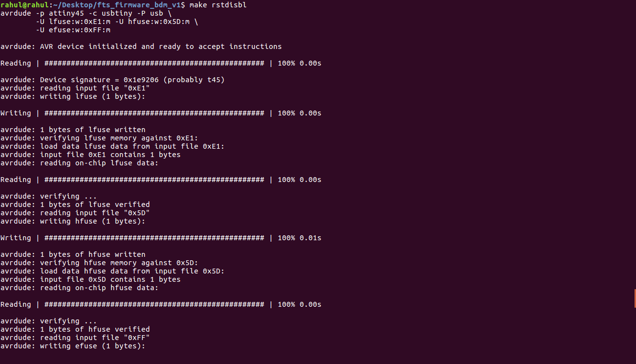
This does the same thing as the make fuses command, but this time it's going to include that reset disable as well. You should see some progress bars, and with that, avrdude will never be able to talk to this chip again through the ISP header. Now your programmer is finished. Test your programmer by using it to program another board.
My instructor was with me when we programmed the board, and surprisingly apart from the initialization failed rc= -1 We faced no other error. We had to adjust the connection of USB programmer a few times while programming.
rahulsrajan.com
rahulsrajan01@gmail.com
Trivandrum, Kerala ,
India.

Technopark, Kerala, India