In this week our main task is to learn how to interface a sensor and read data from it. I wanted to try to learn how to use the ultrasonic range finder sensor as I'm planning on using it for my final project.
This week was difficult for me as I'm from a mechanical background. I was lost in the beginning thinking about what I can do. Its not the sensors I'm having difficulty with- I understand how they work- but Its how they need to be programmed, where I'm stuck at.
After the lecture I went through Neil's code one by one in hopes of understanding them, but compared to my current level of knowledge, they are beyond me. I hope to someday read and understand his code.
For this week I'm going to be relying on Ardunio code till I can get my training wheels off in AVR-C.
The one main thing I understood in sensors is that you need to know how ADC works, this is fundamental. Most sensors respond to the changes in physical properties in a continuous manner, which produces an analog signal. So in order for the micro controller to understand what is happening we need to convert these continuous signals into discrete ones. Hence the function of an ADC.
In brief, what an ADC does is that it samples data at certain intervals so that you can convert a continuously varying signal into a set of discrete values. It uses either an 8 bit or a 10 bit counter to store the values. 8 bit gives you 2^8 bits of storage (256 bits) and 10 bit gives you 2^10 bits of storage (1024 bits)
Here is a great page I found, which explains it beautifully.
This week i did not want to make a dedicated board just to connect one sensor, I wanted to make a board which I could use in my final project as well. Hence I went with satsha kit. I liked the layout of the board and the similarity it has to an Arduino board.
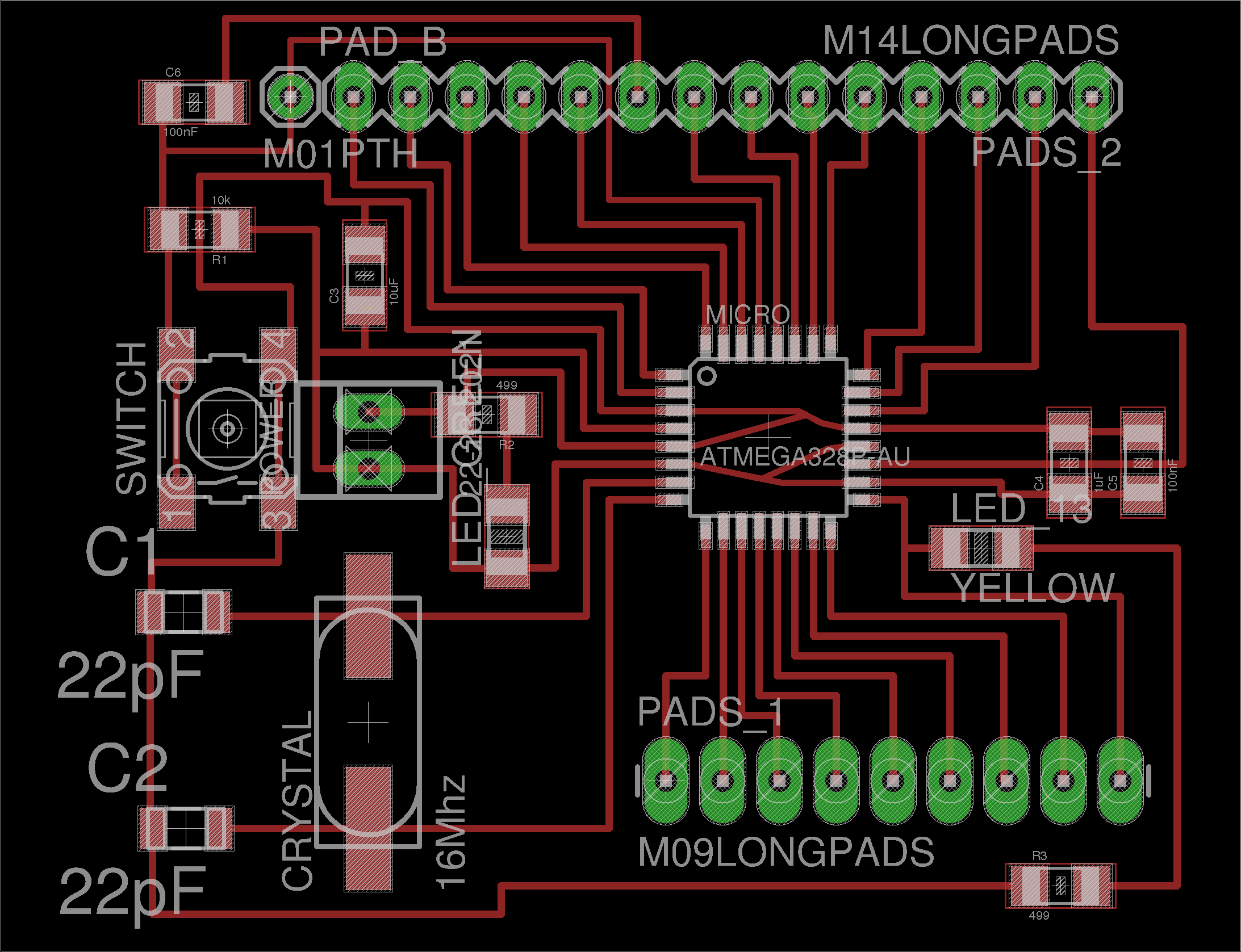
I could not use the satsha kit directly as we did not have the some parts like the 16Mhz Crystal nor the 22pF capacitors, Hence I decided to modify the board to use a 20MHZ resonator instead. Resonators are less accurate than crystals but its more than enough for my projects.
I edited the board file in Eagle and added the pad for the resonator.

I exported them as a .png and also added a FAB logo to it.


Some things which I really like about the board is the simplicity of it, and its beautifully routed, Its meant to be a ready to use arduino board. You can burn the bootloader to it and it even has the same pinouts of an arduino Mega.
One major problem I faced or which I did not think about before hand, was the absence of a power board. The board only had two power connections, One VCC and GND, so if it I wanted to connect a sensor to it, I would have to look for a separate power source and connect their GNDs together. This proved to be a bottleneck when interfacing with sensors
Some things which I don't like about is that, you have to mess around with a lot of jumper wires when you program it and when you want to connect it to an FTDI cable. Its very cumbersome when you want to quickly test your code, you have to connect six wires to program it, and then connect 5 wires to make an FTDI connection. This will take some time and a lot of additional wires. In the future I'm planning on making it a double sided board and put some power connections, and a separate ISP header and FTDI header to it.
I have made another modified version of this board which addresses all these issues, I've documented it on my Final Project page

I used FAB modules and Roland MDX-20 to mill the board. The Traces were cut with a 1/64 inch end mill and the Drill/ Cut lines were done with a 1/32 inch end mill with all the default settSings.

There is a mysterious line at the bottom of the board. I don't know where it came from, it must have happened when I edited the .png in Mycrosoft PAINT to add the FAB logo. Thankfully it does not mess with the traces and can be left alone there.

The traces and the cut lines came beautifully, The traces are really thin and I need to take care in soldering them, as the are really easy to peel off if you mess with them.

Soldering the Atmega A328 was the hardest part of the job. I have never soldered pins this small and this close together. I'm thankfull I have some previous experience soldering Micro controllers. The trick is to Align the IC first by soldering one leg and then fix all the rest of the legs and come back and fix the first one.
I've seen some of my friends put solder on all the pads then trying to fix them to the board, It did not went well. I learned how to do it from one of my instructors. When soldering any SMD components take this rule to heart. First put some solder on one of the pad (Only one not all the pads) using the tweezer, put the IC on the soldered pad and align its legs all the other pad. Now apply heat on the soldered pad and let it cool. The solder should hold the IC in place. Now solder all other legs and come back and properly solder the first Pad. Now you are done.

After the IC is soldered on the rest is a walk in the park, very few components to solder and the you only have to worry about the polarity of some of the components when you solder them.


The ultrasonic sensor works on the principle of Sonar. The way it works is that it sends out a pulse of sound and waits to listen to the Echo from it. the time taken by the echo tells you how far the object is aways from you. Since the speed of sound is relatively fixed, you can get accurate distance reading from 3cm up to 300cm.
In the sensor module I'm using it has two sensors, one a transmitter and another a receiver. It is possible to do this with just one. When using one sensor you have to alternatively switch between sending a pulse and listening for the echo.

The absence of a power connection meant that I had to power the sensor from a different power source and connect their grounds together. Hence I used a variable power supply from our lab, set to constant 5V and connected it to the sensor.

I researched online to know more about programming the Ultrasonic sensor, and I found some resources from the Internet that helped me a lot. It explained clearly how the board needs to be programmed.
Here is the final code for the ultrasonic range finder. The code sends a pulse to the sensor to initiate a reading, then listens for a pulse to return. The length of the returning pulse is proportional to the distance of the object from the sensor.
/*
   The circuit:
  * VCC connection of the sensor attached to +5V
  * GND connection of the sensor attached to ground
  * TRIG connection of the sensor attached to digital pin 2
  * ECHO connection of the sensor attached to digital pin 4
   Original code for Ping))) example was created by David A. Mellis

 */


const int trigPin = 2;
const int echoPin = 4;

void setup() {
  // initialize serial communication:
  Serial.begin(9600);
}

void loop()
{
  // establish variables for duration of the ping,
  // and the distance result in inches and centimeters:
  long duration, inches, cm;

  // The sensor is triggered by a HIGH pulse of 10 or more microseconds.
  // Give a short LOW pulse beforehand to ensure a clean HIGH pulse:
  pinMode(trigPin, OUTPUT);
  digitalWrite(trigPin, LOW);
  delayMicroseconds(2);
  digitalWrite(trigPin, HIGH);
  delayMicroseconds(10);
  digitalWrite(trigPin, LOW);

  // Read the signal from the sensor: a HIGH pulse whose
  // duration is the time (in microseconds) from the sending
  // of the ping to the reception of its echo off of an object.
  pinMode(echoPin, INPUT);
  duration = pulseIn(echoPin, HIGH);

  // convert the time into a distance
  inches = microsecondsToInches(duration);
  cm = microsecondsToCentimeters(duration);

  Serial.print(inches);
  Serial.print("in, ");
  Serial.print(cm);
  Serial.print("cm");
  Serial.println();

  delay(100);
}

long microsecondsToInches(long microseconds)
{
  // According to Parallax's datasheet for the PING))), there are
  // 73.746 microseconds per inch (i.e. sound travels at 1130 feet per
  // second).  This gives the distance traveled by the ping, outbound
  // and return, so we divide by 2 to get the distance of the obstacle.
  return microseconds / 74 / 2;
}

long microsecondsToCentimeters(long microseconds)
{
  // The speed of sound is 340 m/s or 29 microseconds per centimeter.
  // The ping travels out and back, so to find the distance of the
  // object we take half of the distance traveled.
  return microseconds / 29 / 2;
}
The code is pretty straight forward, It sends out a pulse and waits for the Echo to return and counts the microseconds time it took for the echo to reach back. Now calculate the distance based on the speed of sound in air and take half the value since the sound is traveling back and forth.
In the video you can see the sensor is connected to the board via jumper cables and powered by and external power source with a common ground. The board is connected via FTDI to the computer. I'm receiving data from the board via serial monitor in the Ardunio IDE. The data I'm getting is the distance measured by the sensor in the time interval.
As I'm moving my arm up and down, the distance reading from the sensor changes, which is seen as the change in numbers on my screen.
It works well, I can get reasonably accurate results from the range finder, the minimum resolution is around 3 cm and the maximum about 300 cm. The only problem with it is that it needs a relatively perpendicular object to bounce the sound from. If the object is not perpendicular to the sound waves then they get deflected off and the echo takes a lot longer to reach the sensor, thus giving a wrong distance reading.
I really Like the principle behind step response in Neil's Lecture, and I wanted to try it out on my own. It is such a versatile method, you can make a lot of sensors with just a piece of foil and a simple circuit.
I understood the concept of it, we humans have a certain internal resistance and we can act as a capacitor connecting the circuit and the ground potential of earth. So if we made contact with a charged plate, its capacitance varies. Hence we can measure that by the way the plate charges and discharges.

In step response you place a large resistance in series with a foil or plate and charge and discharge it continuously, When a human is in contact with this, there will be a variation the way these pates charge up and we can measure this variation and convert them into touch data.
The sensitivity of the touch pad depends on the resistance you use to charge the pad. For a simple touch activated pad, you can use some value about 1M ohm resistor. As you increase the resistance you can increase the sensitivity of the pad.
.
As we only have SMD components in the lab, I had to solder the 1M Ohm resistor to two jumper wires. The lack of breadboard connectivity is a problem as I cannot quickly switch out a resistor to a new one and test out the result.
The touch pad was made from some foil, which I cut and folded into a rectangle, the sensitivity of the pad can be increased with increase in the area of the pad.

Here is the arduino code for the capacitive touch sensor. In order to run this code you must have the Capacitative sens library installed in your system.
#include <CapacitiveSensor.h>

int led = 13;
long time = 0;
int state = HIGH;

boolean yes;
boolean previous = false;

int debounce = 200;

CapacitiveSensor   cs_4_2 = CapacitiveSensor(4,2);        // 10M resistor between pins 4 & 2, pin 2 is sensor pin, add a wire and or foil

// To add more sensors...
//CapacitiveSensor   cs_4_6 = CapacitiveSensor(4,6);        // 10M resistor between pins 4 & 6, pin 6 is sensor pin, add a wire and or foil
//CapacitiveSensor   cs_4_8 = CapacitiveSensor(4,8);        // 10M resistor between pins 4 & 8, pin 8 is sensor pin, add a wire and or foil

void setup()
{
   cs_4_2.set_CS_AutocaL_Millis(0xFFFFFFFF);  //Calibrate the sensor...
   pinMode(led, OUTPUT);
}


void loop()
{
    long total1 =  cs_4_2.capacitiveSensor(30);

    if (total1 > 60){yes = true;}
    else {yes = false;}

    // to toggle the state of state
    if(yes == true && previous  == false && millis() - time>debounce){

       if(state == LOW){
         state = HIGH;
       }
       else
         state = LOW;
         time = millis();

    }


      digitalWrite(led, state);
      previous = yes;

      Serial.println(millis()-time);
      delay(10);


}
The code works by measuring the time required for the plate to charge, if the time varies, then it knows a person has touched the plate. In order to use it we first have to calibrate the sensor to account for the stray electric field around us. Then you can set the sensitivity of the sensor by changing the value 60 to something else in the code.
You can also edit the debounce value to set how fast your touch pad will respond.
I was amazed at how well it works, step response is awesome, there is a lot of potential in this simple system. I need to explore it further.
rahulsrajan.com
rahulsrajan01@gmail.com
Trivandrum, Kerala ,
India.

Technopark, Kerala, India