Electronics Production
Goals
- Make an in-circuit programmer by milling the PCB
- Optionally, trying other processes.
FabISP
The FabISP is a 100% fab-friendly AVR programmer, based on Dick Streefland's USBtiny; I chose Ali's version, mainly because his documentation is detailed and full of useful links explaining the rationale behind his design decisions.
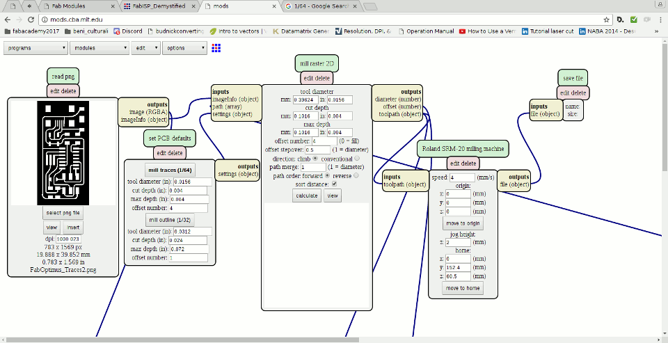
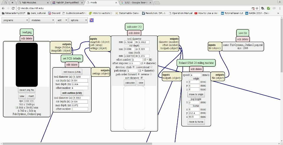
After a quick reading I downloaded the .png files for the inner traces and for cutting the outline of my pcb, processed them with the fabmodules and obtained the .rml files (1), (2) for our milling machine.
The milling
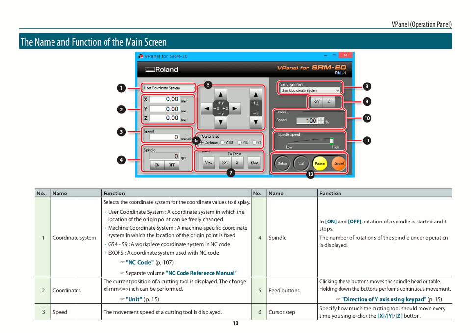
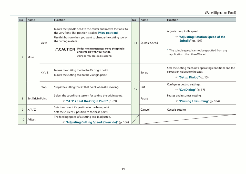
Our lab is equipped with a Roland SRM-20 milling machine, operated via a proprietary software called VPanel; the full manual is availble here, and this is a quick overview of VPanel main interface:
In order to mill my pcb I had to mount the right end into the chuck (we're using a 1/64 inch end for milling the traces and a 1/32 for cutting the actual board), secure the board on the sacrificial layer with a copious quantity of double sided tape (if the pcb is not properly secured the board will move during the milling and all you'll get is a wasted board and, worst case scenario, a bronken endmill), set the X/Y/Z origin (setting the Z can prove to be a bit tricky, more on this later), select the right .rml file and start cutting.
Overconfidence is a slow and insidious killer, as the narrator in a very well made game used to say, and I made my first mistake: I accidentally set my jog height to 0mm in the fabmodules interfaces: turns out this setting controls how much the endmill retracts while traveling and, zeroing it, the drill scrapes the surface of the board:
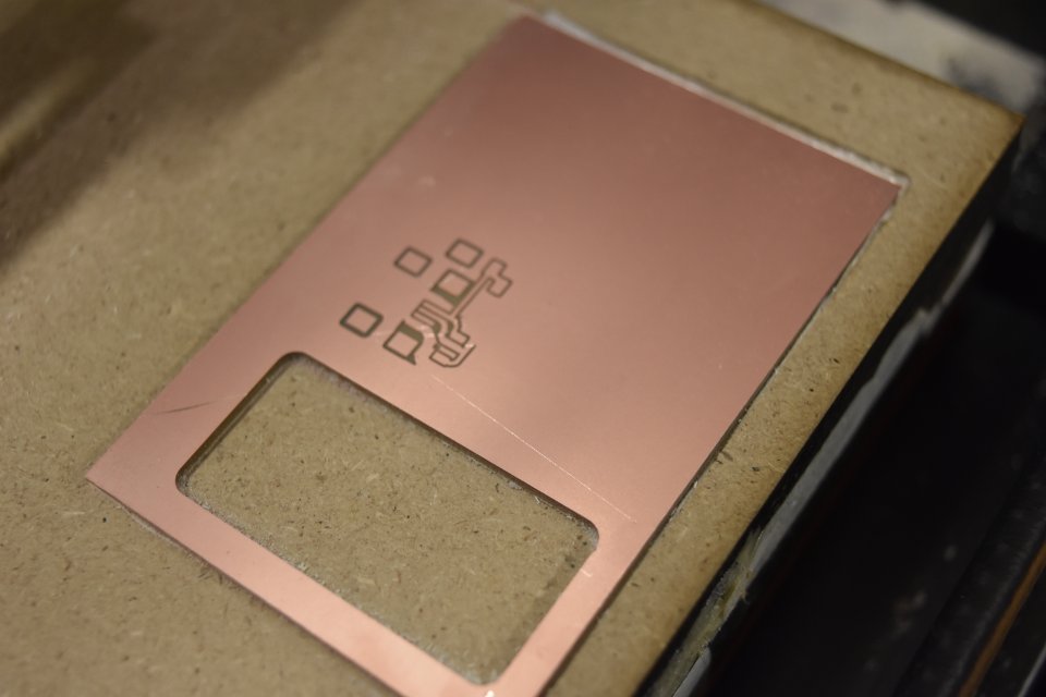
My second mistake was in setting the vertical origin: when doing it it's advisable to slightly press down the endmill, in order to prevent even the slightest retraction while fastening the chuck. Should you fail in doing so the endmills won't cut deep enough.
You can correct this mistake easily enough, without starting from scratch: just set Z again without changing your X/Y origin and start milling again.
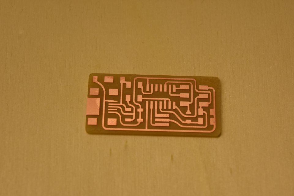
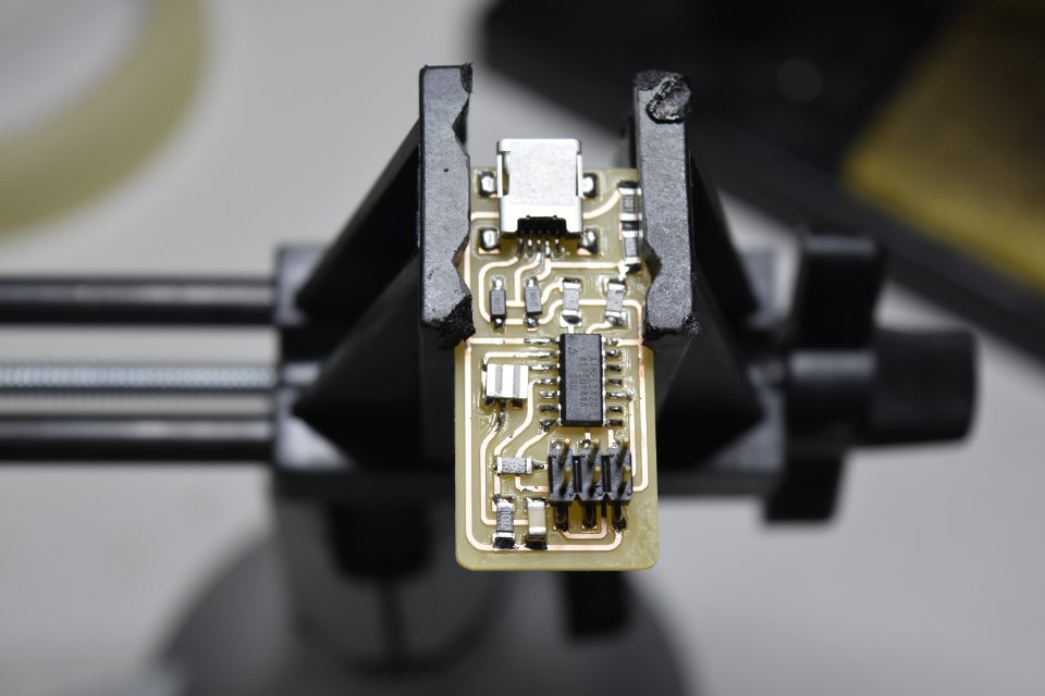
If everything goes well you can extract your milled board and wash it to remove any traces of copper left:
The stuffing
In order to collect the right components in the right quantity I compiled a crude Bill of Materials (BoM from now onwards):
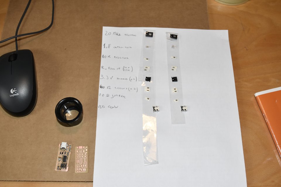
I had never handled a soldering iron before but It was immediately clear to me that surface mounting soldering and prescription glasses are not meant to be together: I tried using a magnifying monocular but it sat badly with my spectacles, and taking them off is unthinkable. In the end I settled for a magnifying lamp, even if took me some time to get used to it (I had problems chiefly with depth perception).
I used this hand-drawn sketch as a reference while soldering:
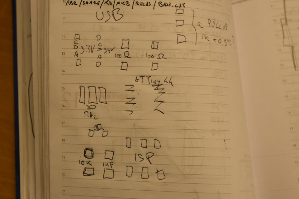
I started soldering the microcontroller (an ATtiny44) and moved forward in an outward spiral pattern, in order to always have enough room to maneuver the soldering iron. Afer some time (much more than I'd like to admit, to be honest) I had my board fully soldered.
Programming the board
Anna Kaziunas France's tutorial is a detailed, step-by-step walkthrough on how to program your FabISP board; after downloading the required libraries and the firmware I only had to modify my Makefile, for I was using a USBtiny device as a programmer (my instructor own FabISP) and not an avrisp2 device: fire up your editor of choice, comment out the line referring to the avrisp2 and replace it with the one about the usbtiny:
AVRDUDE = avrdude -c usbtiny -p $(DEVICE)
#AVRDUDE = avrdude -c avrisp2 -P usb -p $(DEVICE)
After this you can program your board with
make clean
make hex
make fuse
make program
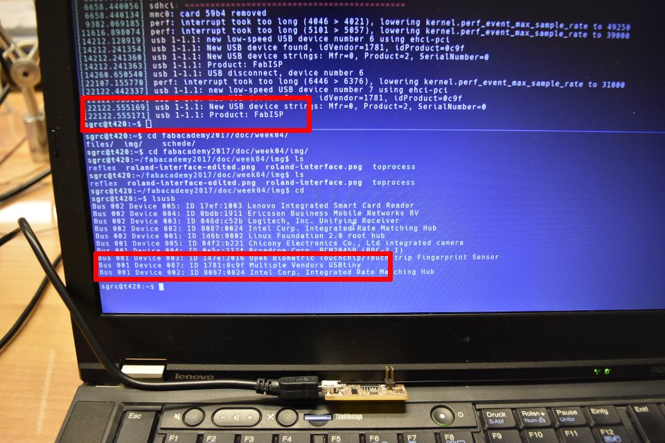
And you're set, your FabISP should now be listed as "ID 1781:0c9f Multiple Vendors USBtiny" in a "lsusb" output.
In order to use your newly made board as a programmer you have to remove the 0Ω jumper.
In my case things didn't worked on the first try, and got this error output from the "make program":
sgrc@t420:~/fabacademy2017/doc/week04/schede/01/fabISP_mac.0.8.2_firmware$ sudo make program
avrdude -c usbtiny -p attiny44  -U flash:w:main.hex:i

avrdude: AVR device initialized and ready to accept instructions

Reading | ################################################## | 100% 0.00s

avrdude: Device signature = 0x1e9207 (probably t44)
avrdude: NOTE: "flash" memory has been specified, an erase cycle will be performed
         To disable this feature, specify the -D option.
avrdude: erasing chip
avrdude: reading input file "main.hex"
avrdude: writing flash (1986 bytes):

Writing | #######################                            | 46% 0.98s
avrdude: error: usbtiny_send: error sending control message: Broken pipe (expected 64, got -32)
Writing | ################################################## | 100% 3.29s

avrdude: 1986 bytes of flash written
avrdude: verifying flash memory against main.hex:
avrdude: load data flash data from input file main.hex:
avrdude: input file main.hex contains 1986 bytes
avrdude: reading on-chip flash data:

Reading | ################################################## | 100% 3.27s

avrdude: verifying ...
avrdude: verification error, first mismatch at byte 0x0000
         0x00 != 0x2b
avrdude: verification error; content mismatch

avrdude: safemode: Fuses OK (E:FF, H:DF, L:FF)

avrdude done.  Thank you.

Makefile:124: recipe for target 'flash' failed
make: *** [flash] Error 1
Even for somebody lacking any experience of such things lik me the error happeared to be quite self explanatory: something went wrong during the writing of "main.hex" and the resulting file differed from the source one. For a more thorough examination let's open the Makefile at line 124:
# rule for uploading firmware:
flash: main.hex
	$(AVRDUDE) -U flash:w:main.hex:i
regarding the -U flag, avrdude man page states:
 -U memtype:op:filename[:format]
                   Perform a memory operation as indicated.  The memtype field specifies the memory type to operate on.  The available mem‐
                   ory types are device-dependent, the actual configuration can be viewed with the part command in terminal mode.  Typi‐
                   cally, a device's memory configuration at least contains the memory types flash and eeprom.  All memory types currently
                   known are:
                   [...]
                   flash        The flash ROM of the device.
                   [...]
After all this I still had no clue on how to solve the issue. Out of pure frustration I tried switching USB port on my laptop and everything went smoothly. The same problem arouse for other people here in the lab, so we make several tests and traced the origin back to a faulty USB cable.
Here is a screenshot of my pc with the fabisp plugged in and properly recognized as a Usbtiny derivated device (those outputs are from a "dmesg" and "lsusb" commands in a GNU/Linux environment).
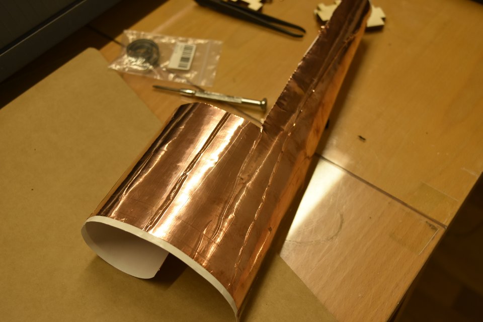
Vinyl cutter
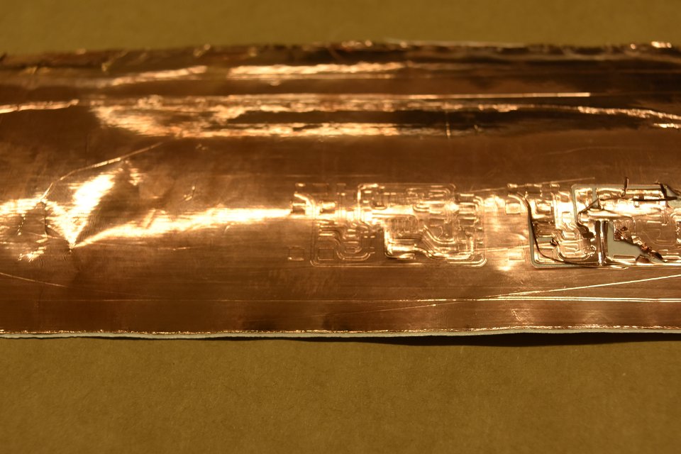
Out of curiosity I tried to cut the traces for my FabISP with the GS-24 vinylcutter; I had few hopes for it to work, since the material avaible at the lab was quite worn out and full of creases:
In order to get the toolpaths for the vinyl cutter I used the fabmodules as described in the relevant section of last week's documentation (here is a quick link).
A first try was done with force: 30g and speed: 3cm/s. The outcome was a total disaster, for the blade begun pulling and trashing the traces.
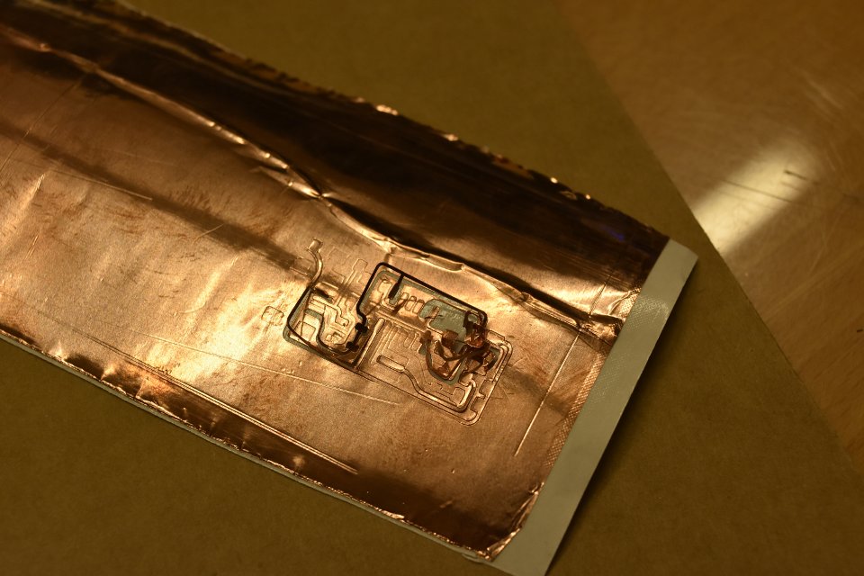
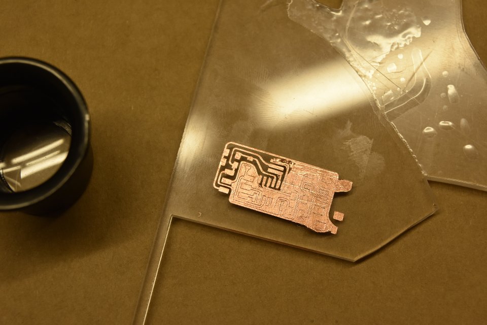
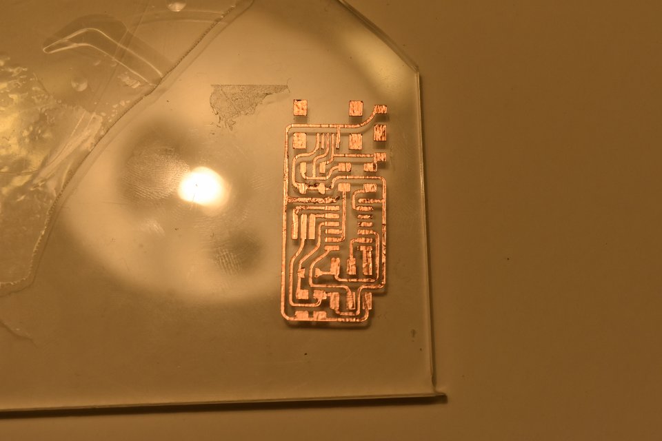
I tried again, lowering both force and speed: 20g and 0.5cm/s (I'm quite sure, though, that the vynil cutter automatically corrected my speed to 1cm/s). This time the outcome was way better, even if some of the thinner traces weren't completely cut, just engraved (this proved to be quite problematic later on, when I had to tweeze out the copper in excess)
With the aid of some transfer tape I moved my circuit on a scrap of plexiglass lying around in the lab and started working on it with a loupe and a pair of tweezers
Files
- week 04 files - archive containing all the working files