WEEK 3 - COMPUTER CONTROLLED CUTTING
Introduction
The assignment for this week was:
- cut something on the vinylcutter
- design, make, and document a parametric press-fit construction kit, accounting for the lasercutter kerf, which can be assembled in multiple ways
VINYLCUTTER
Before starting to use the vinylcutter I had to instal the software (Cut Studio) on a Windows computer. I have a Macbook and Roland didn't have a software for Mac OS. On Roland's web site I had looking for the software Roland Onsupport and I have downloaded it with my computer and installed it on the lab pc without an internet connection.
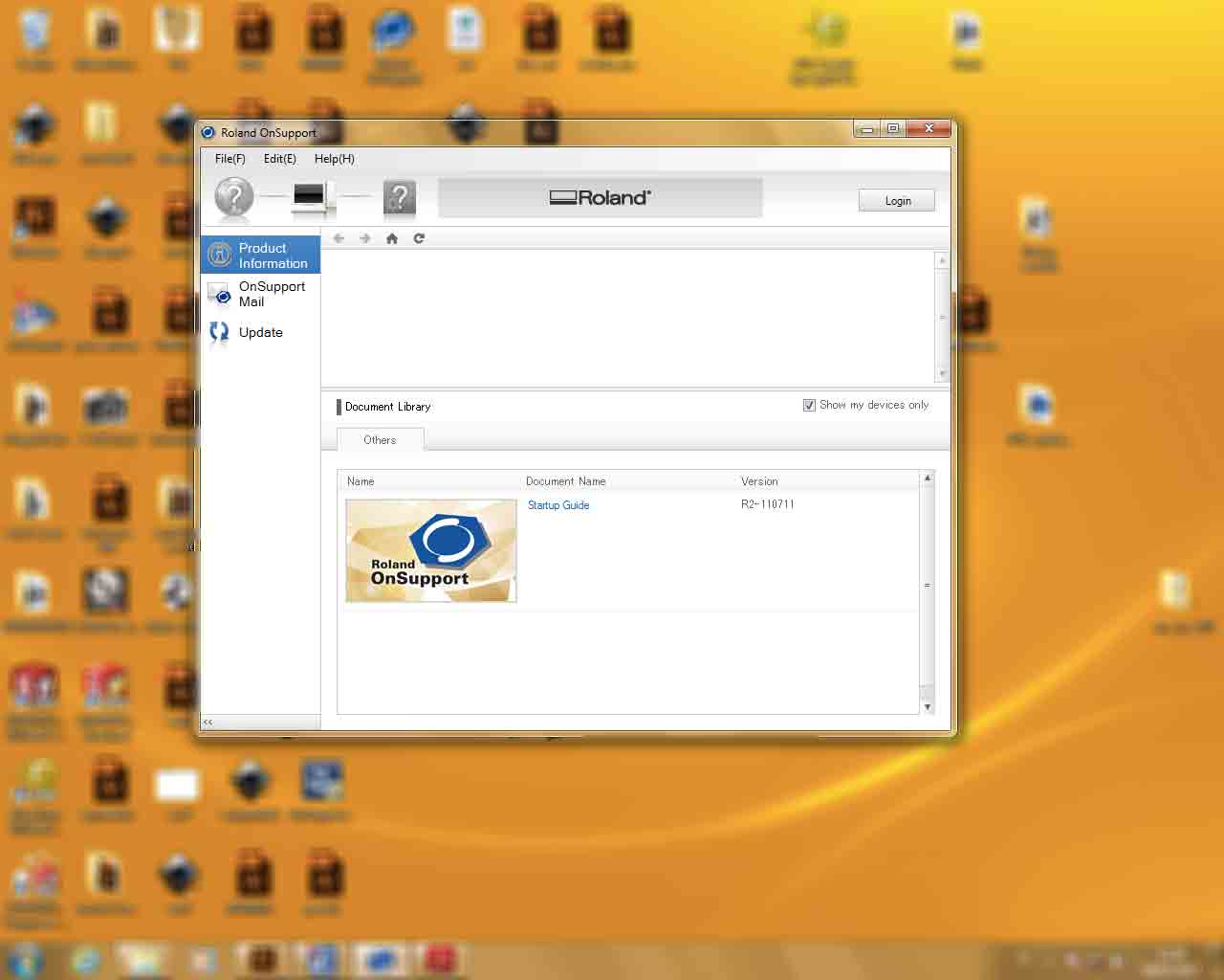
After that I have connected the vinylcutter to the computer and a new problem come out. The computer couldn't find the printer. Panic! Why did the Pc couldn't find it? First of all I have connected the computer to internet, but I haven't solved the problem, so I have understood: I had to install the printer driver. I had looking for that on Roland site I have downloaded it and installed.
Vinylcutter works! yeah!!
I have decided to print the official logo of my favorite 90's pop band, so I have downloaded it from internet and I have opened it with Illustrator. I have traced the image to make it vectorial.

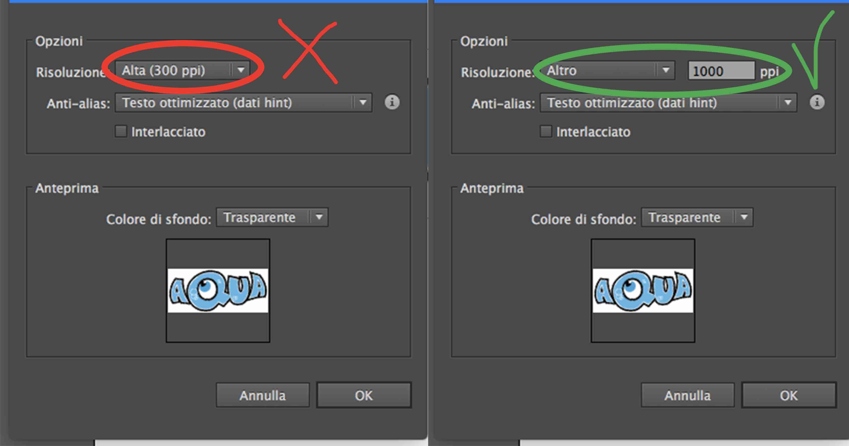
It's time to save it. Cut Studio only recognizes .png files not .ai files, so I have saved my sticker with this extension. But I have done a mistake. I have saved my picture with a low value of ppi, so it had a low quality. The right value for was 1000ppi, in that way I can have an high quality pic.
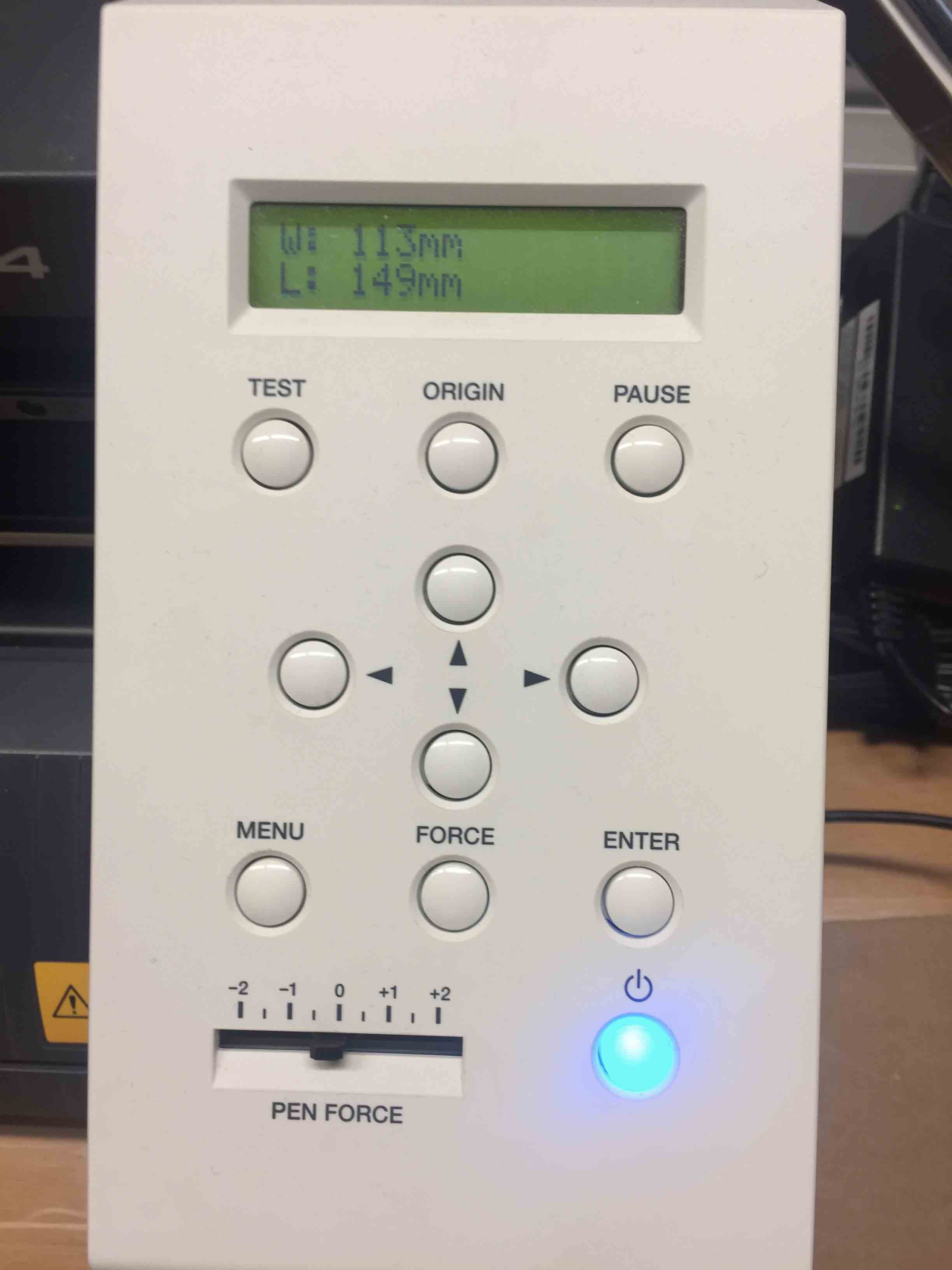
After have saved it, I have imported the file on Cut Studio for prepare it for the print. I have resized it with the correct meauseres, and after that I have changed the parameters for cut. For our vinyl the right values was:
- Strength of cut: 70 %
- Speed of cut: 5 cm/sec
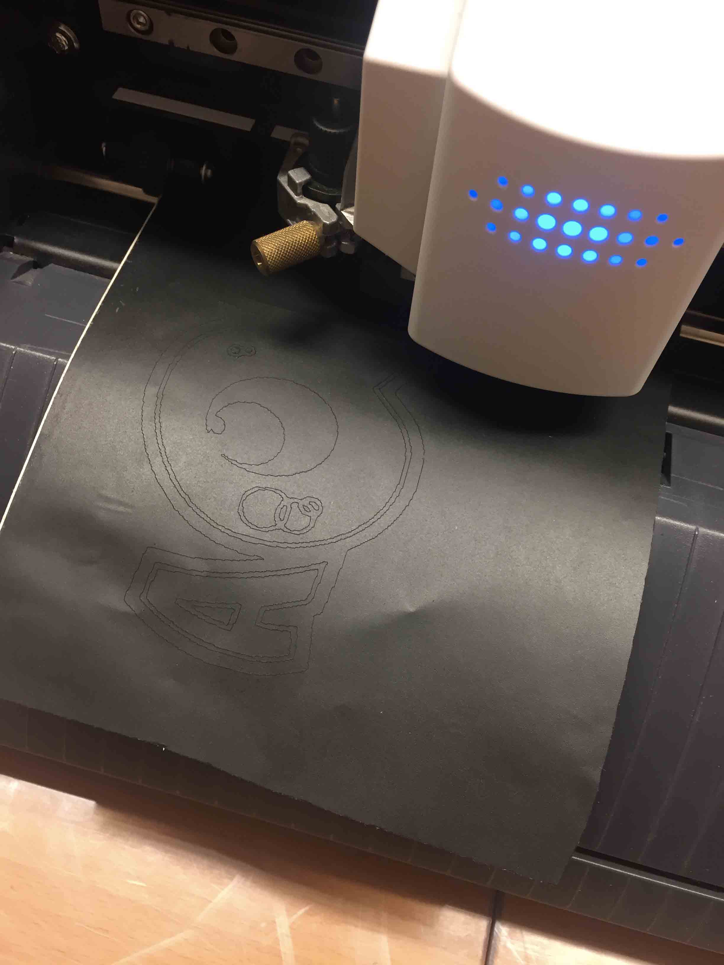
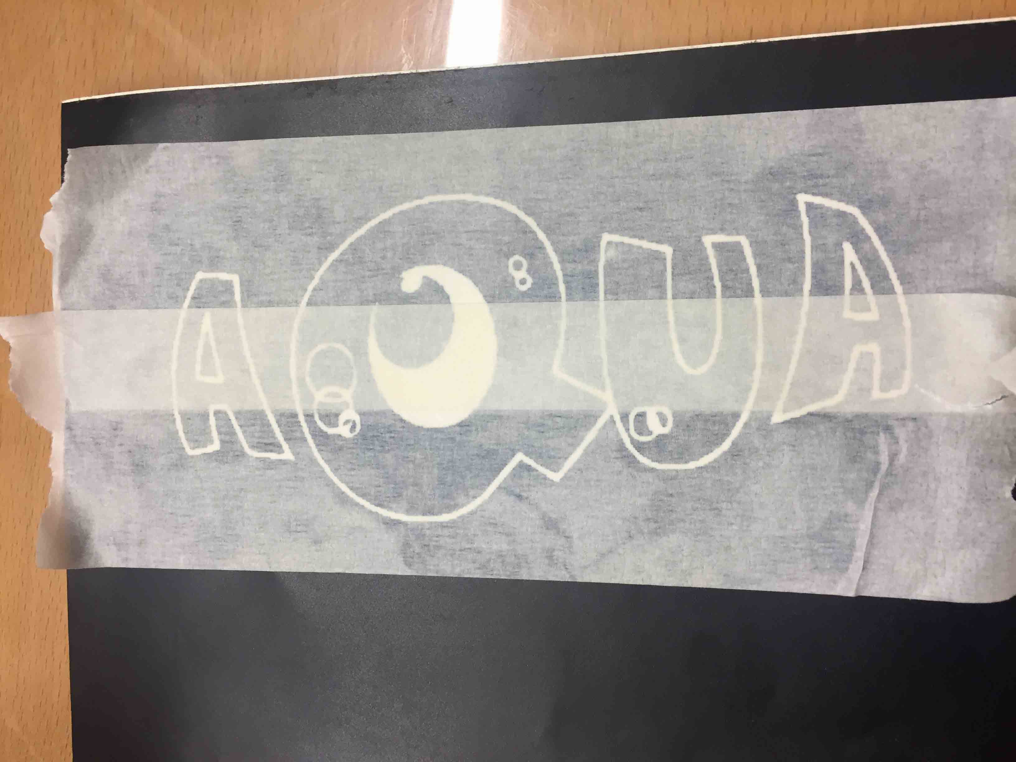
The plotter started to cut and in a few seconds, I had my first sticker. I have removed the extra parts and after that I have used adhesive paper to transfer it on my laptop.
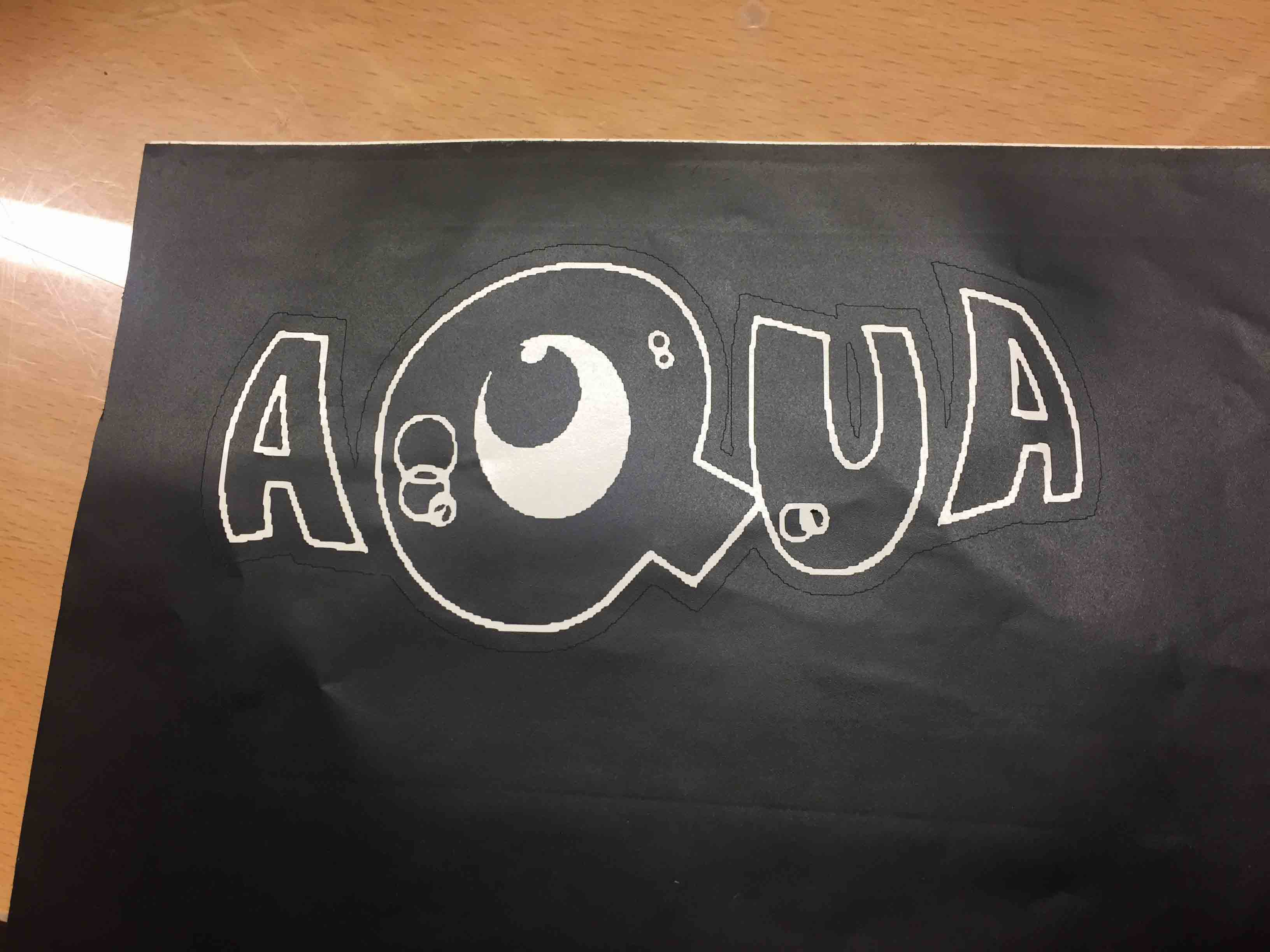
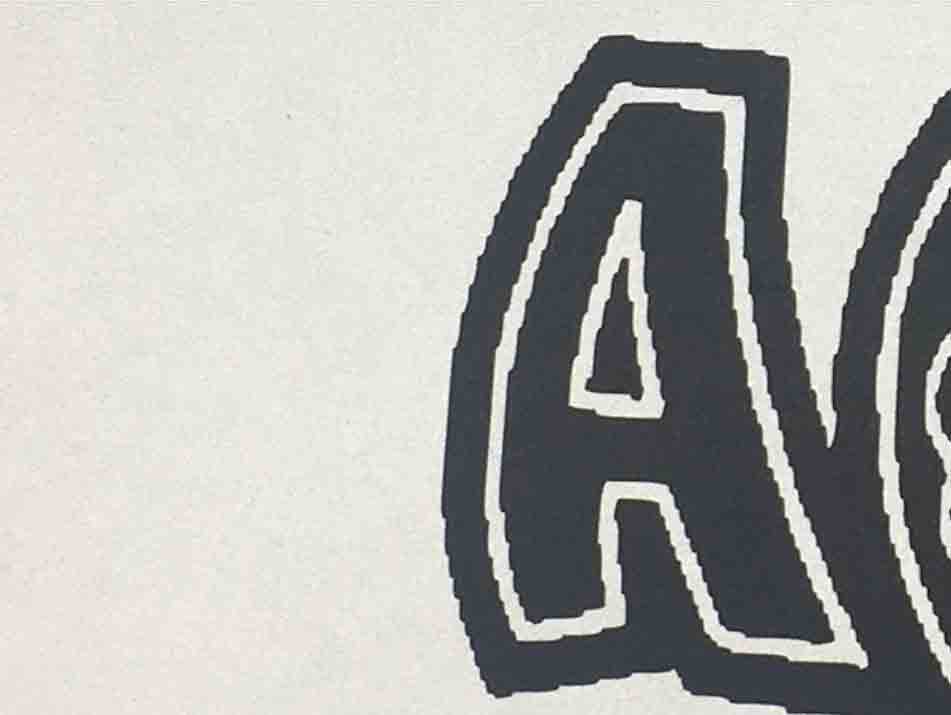
As I have said before this sticker wasn't correct because I haven't increase the quality of the image, so the result was a pixelated sticker.
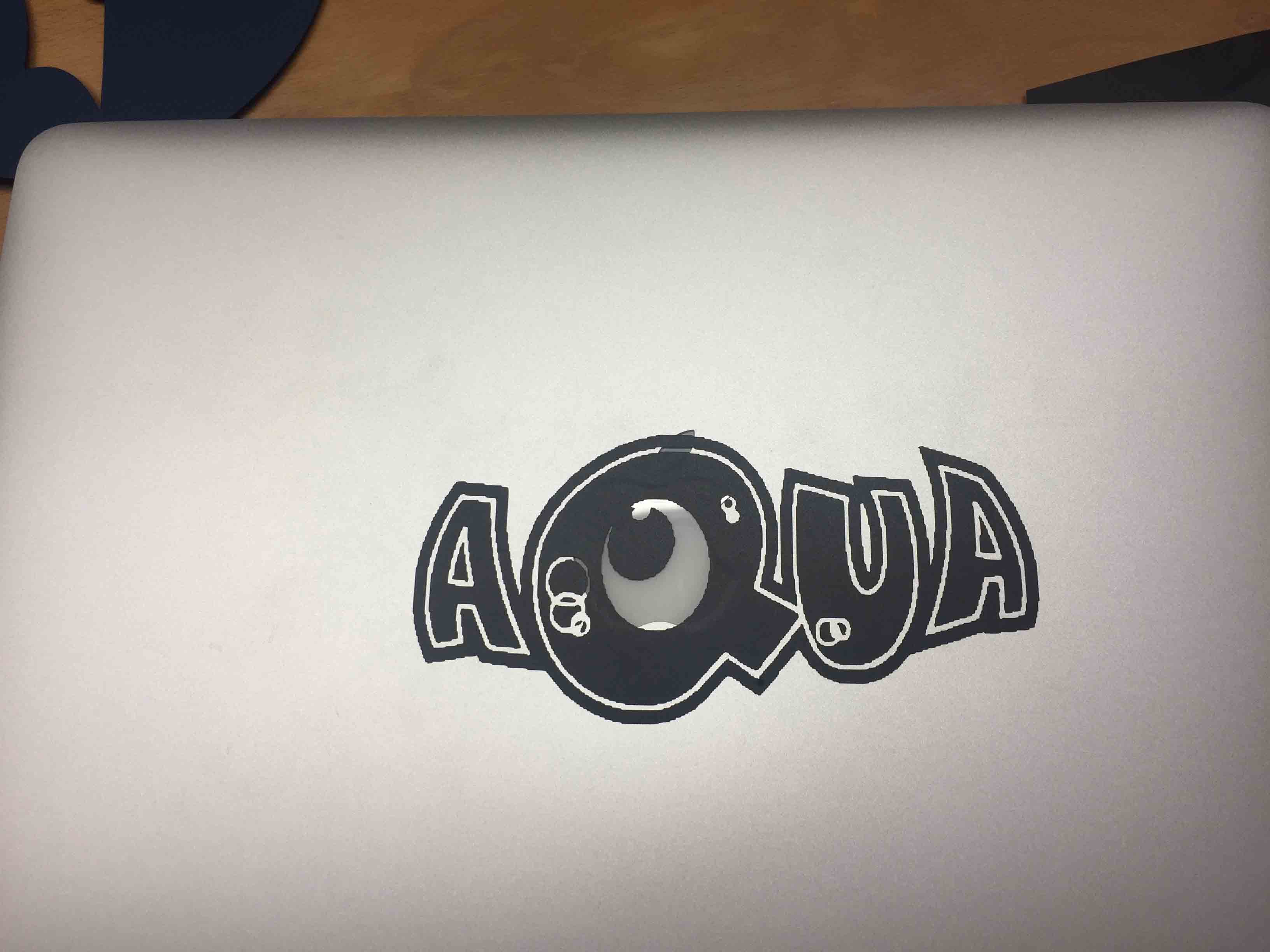
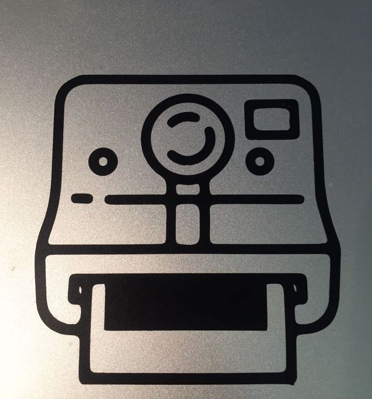
I have decided to make another attempt. I have changed the subject of the sticker, I have saved the new picture with the right values, I have followed the same process and at the end this was the result.

Our instructor showed to us the Fab Modules . With it I can print my sticker using a cut command from the shell. I have tried to print another sticker, so I have modified my picture with Illustrator as before. After that I have uploaded my picture on Fab Modules.
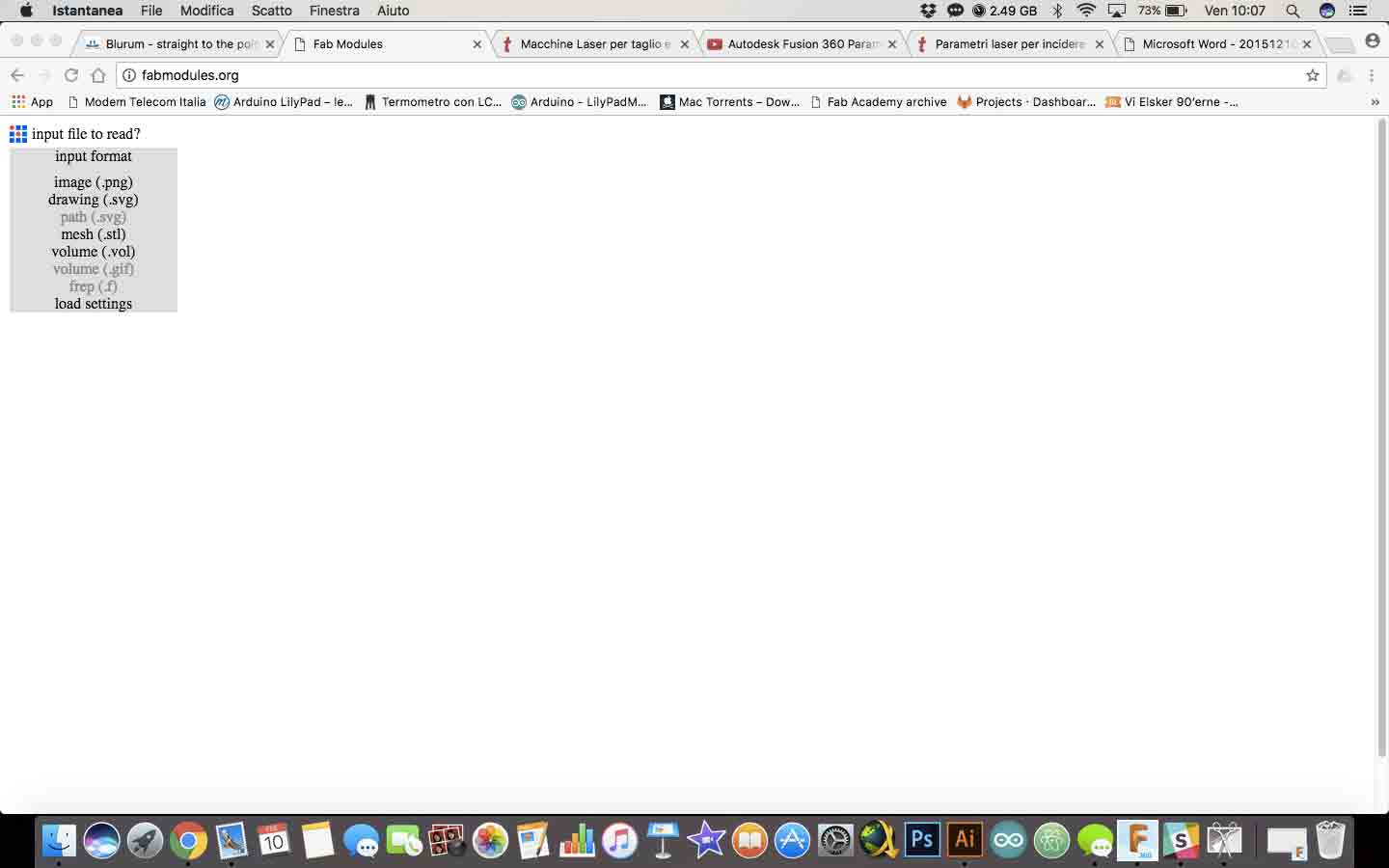
Next step has been to select the output format. I have chosen .camm, which is Roland Vynil extension.
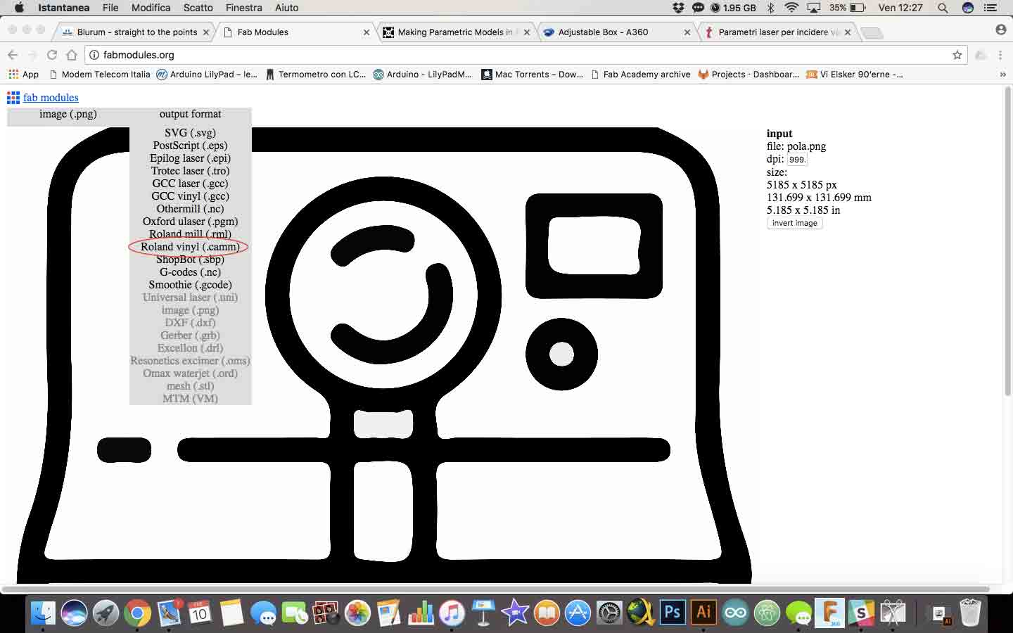
After that I have selected the process to execute (cut vinyl). I could print out my sticker. Unfortunately I couldn't print my sticker because my Mac didn't recognise the vinylcutter. I have tried to fix the problem looking for the driver, but on the Roland Site I have saw there weren't available the driver for the latest update of OSx 10.12.3. Ever using this command it works, always for the same problem:
           dmesg to check whether the lp0 is recognised
              cd directory of the file
              su
              cat filename.camm > /dev/usb/lp0
So to cut it I have used a Linux PC. By terminal I used this command lines and it works. This is my final sticker.
PARAMETRIC PRESS-FIT KIT
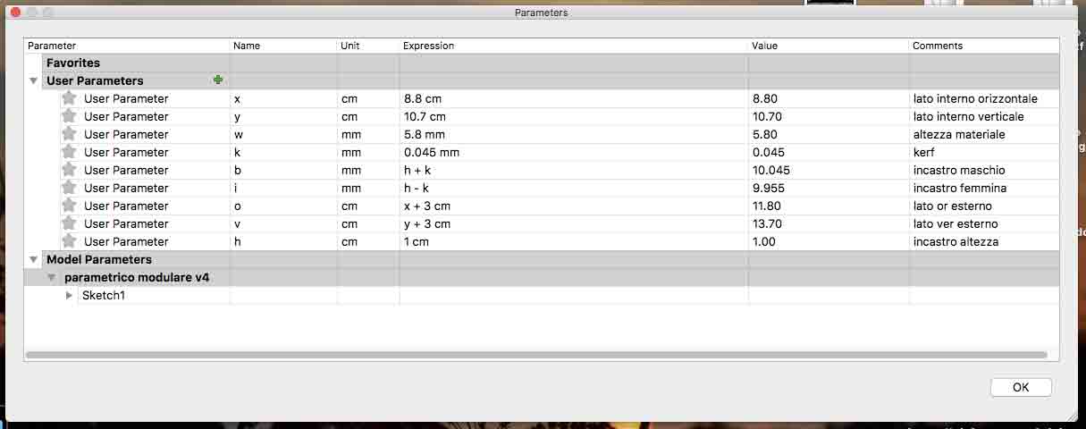
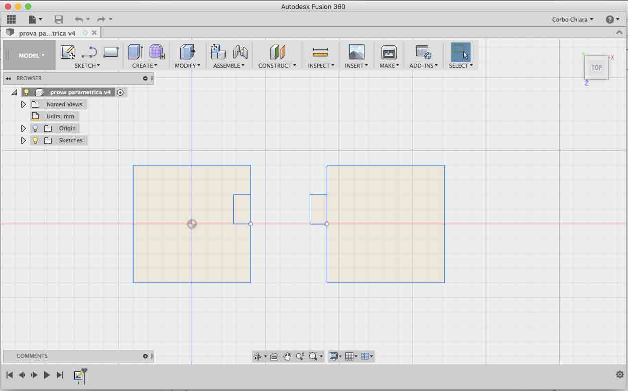
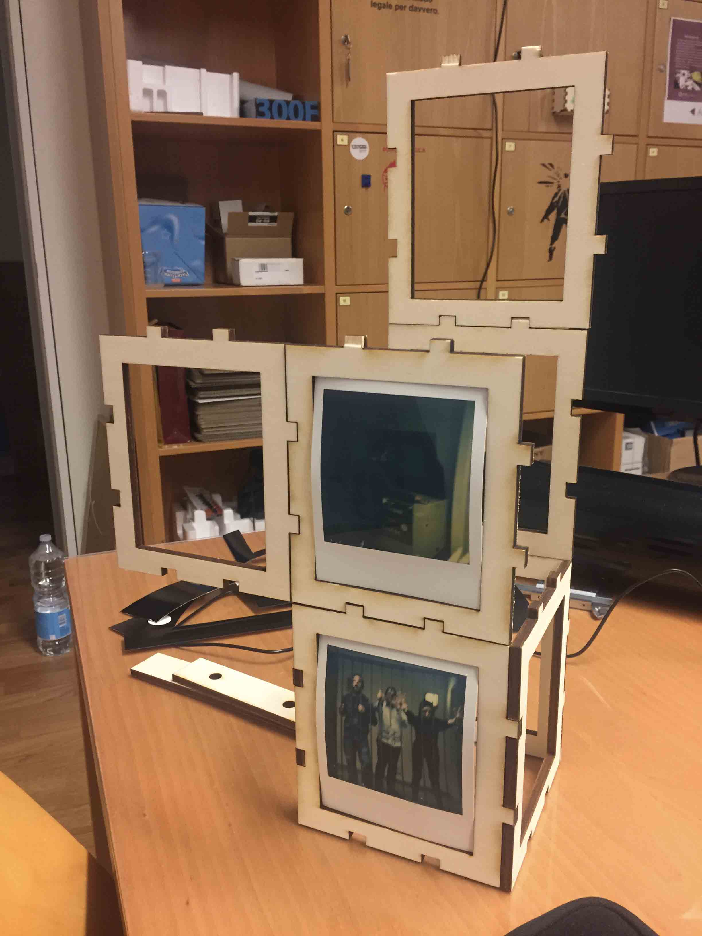
For my press-fit kit I have decided to build a modular frames for my Polaroid. First of all I have done a sketch of my project with Fusion 360 by using parametrics value. For understood how parameters works I have looking for some tutorial and I have find it very usefull (link). I have tried it and I think that was usefull using it because if I need to change a value, my sketch resized automatically.
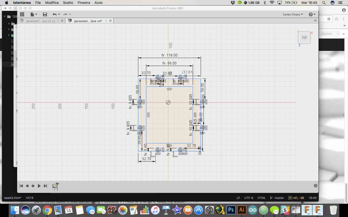
It was easy set the parameters. Fusion 360 have a very simple interface for doing it. On modify choose change parameters. With command + I have added my parameters and after that, I have started to draw.
Before started to cut we had co-work group to test kerf value. You can find our work here
First of all, before started to cut my sketch, I have had a first attempt with a simple joint.
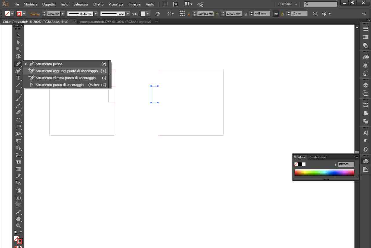
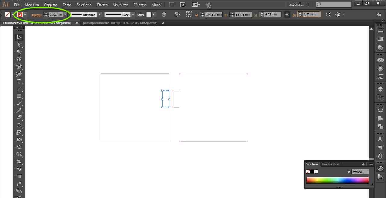
For this I have used a MDF board, not plywood board, for don't waste material for my prototype. First attempt was with 0,1mm kerf. I have opened my sketch on Illustrator (NOTE: It's import export Fusion file in .dxf.) I have forgot to delete a little part of trace, so I have modified my sketch with Illustrator, by adding anchor point on the trace then I have deleted it.
When I have finished to fix my model I have changed boundaries RGB (R=255 G=0 B=0) and thickness with 0,001mm.
I have selecting print command by opening file menu and I have setted right features.
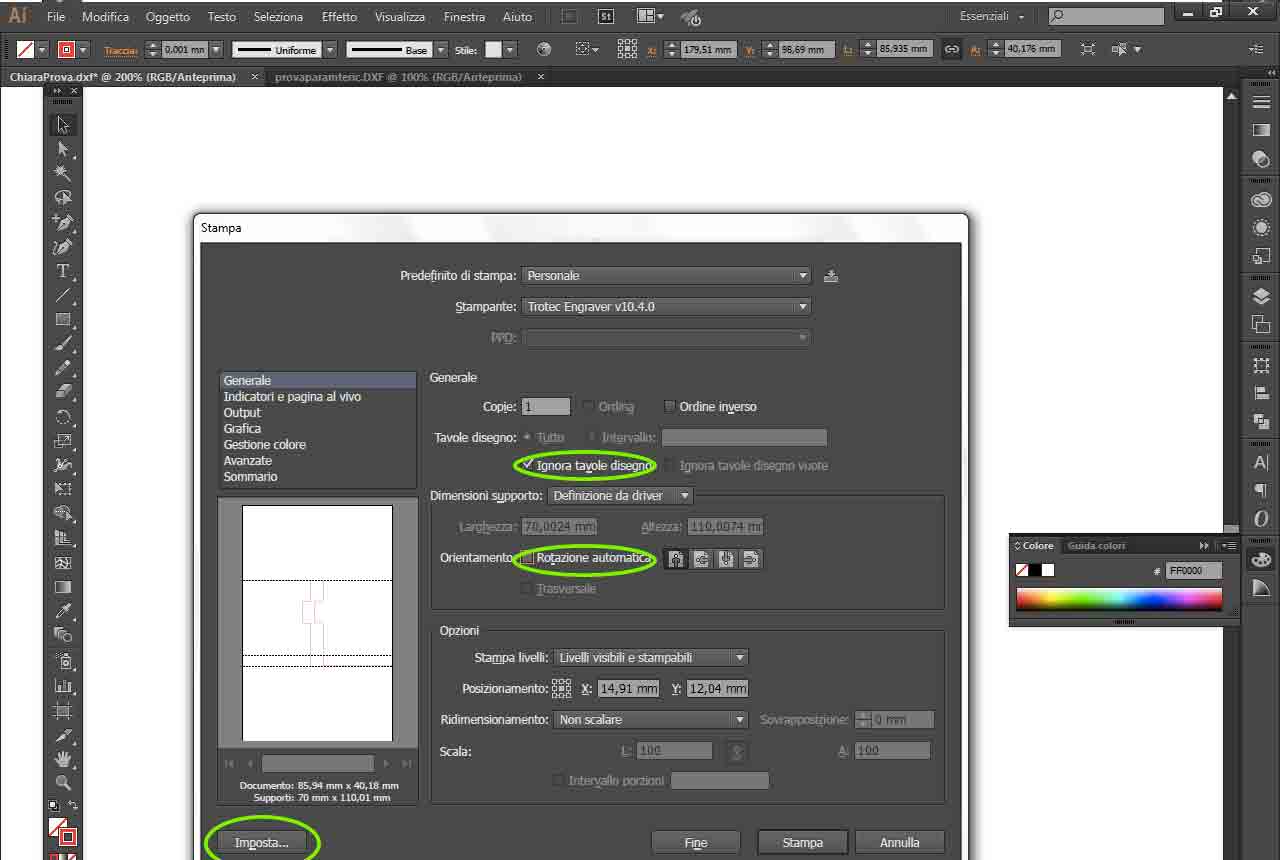
After have selected setup command, click on preferences for open Trotec print setup.
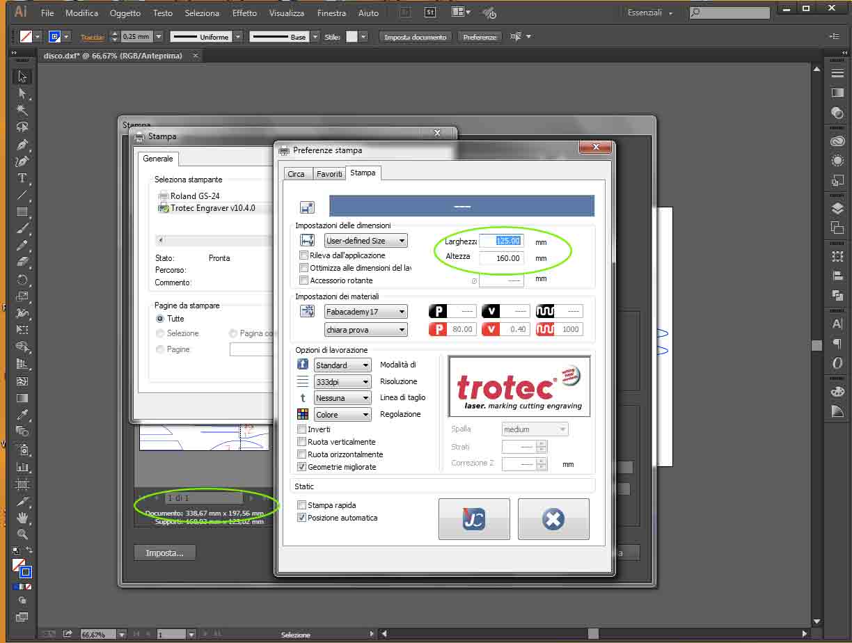
I have changed margin of my documents. I have leaved 2mm for each side and then I have clicked on JC button. After that Trotec Job Control will open automatically with my file just on work area.
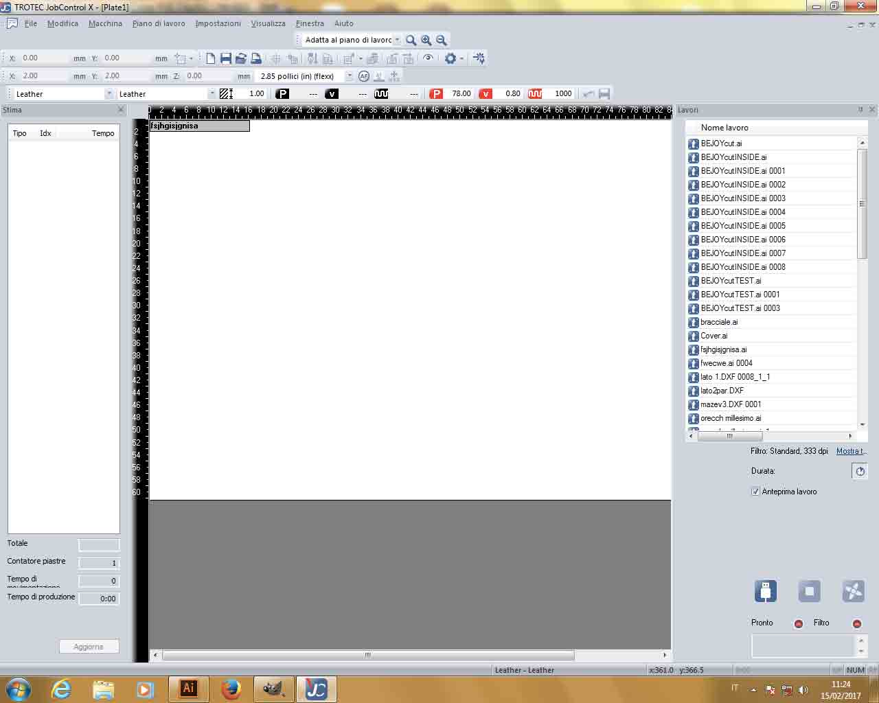
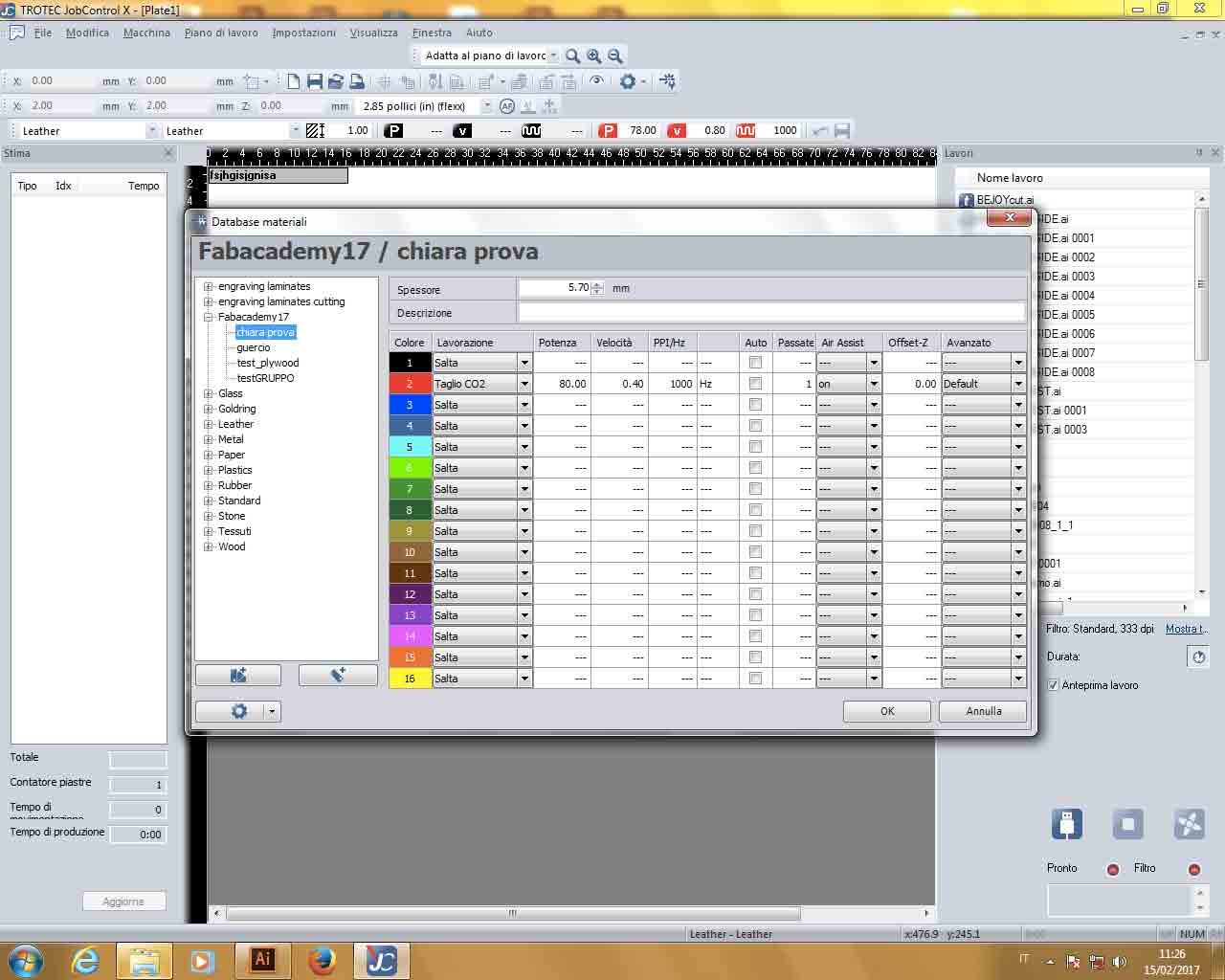
By doble-click on free space of work area, you can choose if cut or engrave and you can set RGB color, power and speed.
Now I had to prepare the lasercutter. This is the trotec shell command.
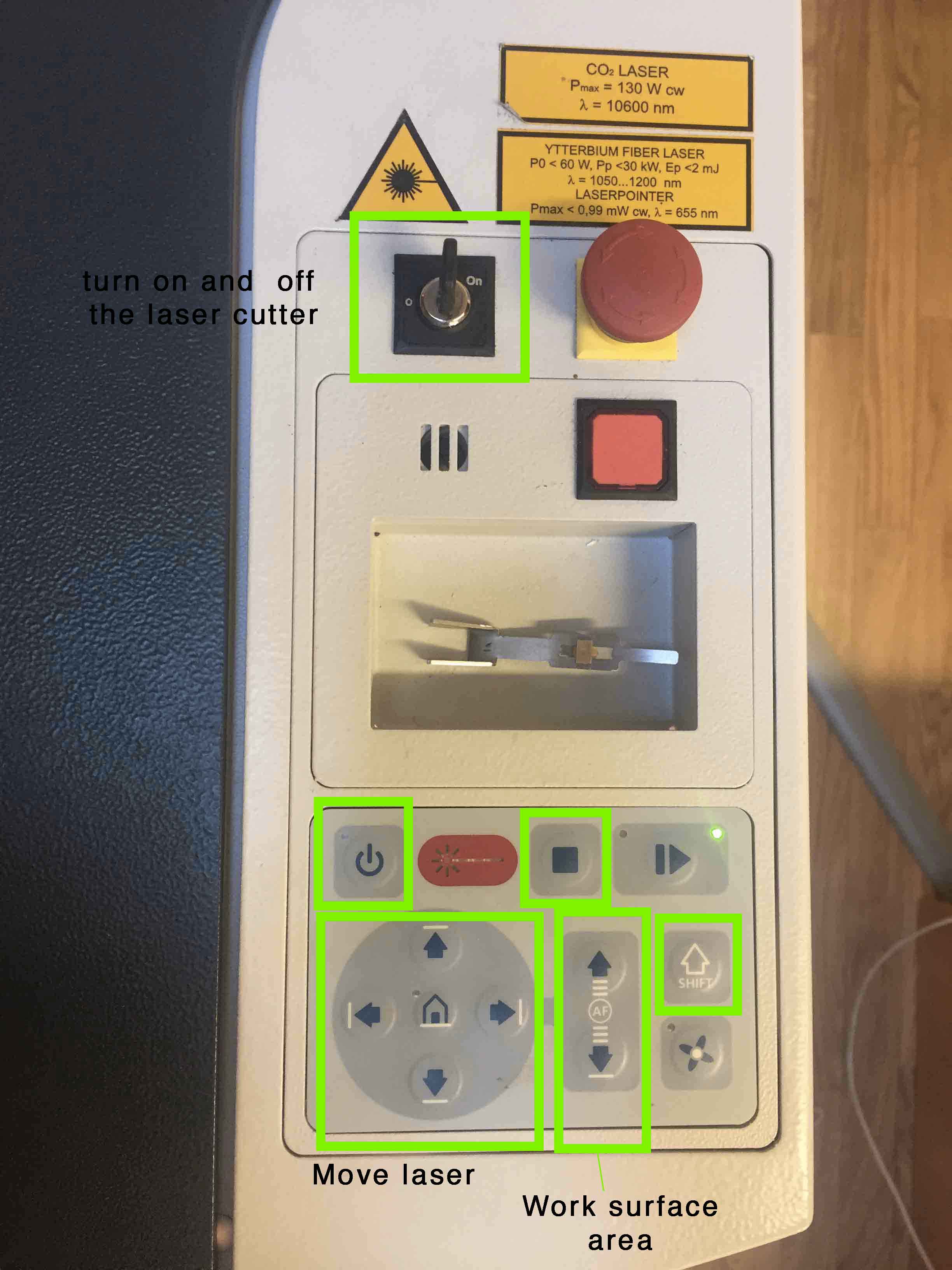
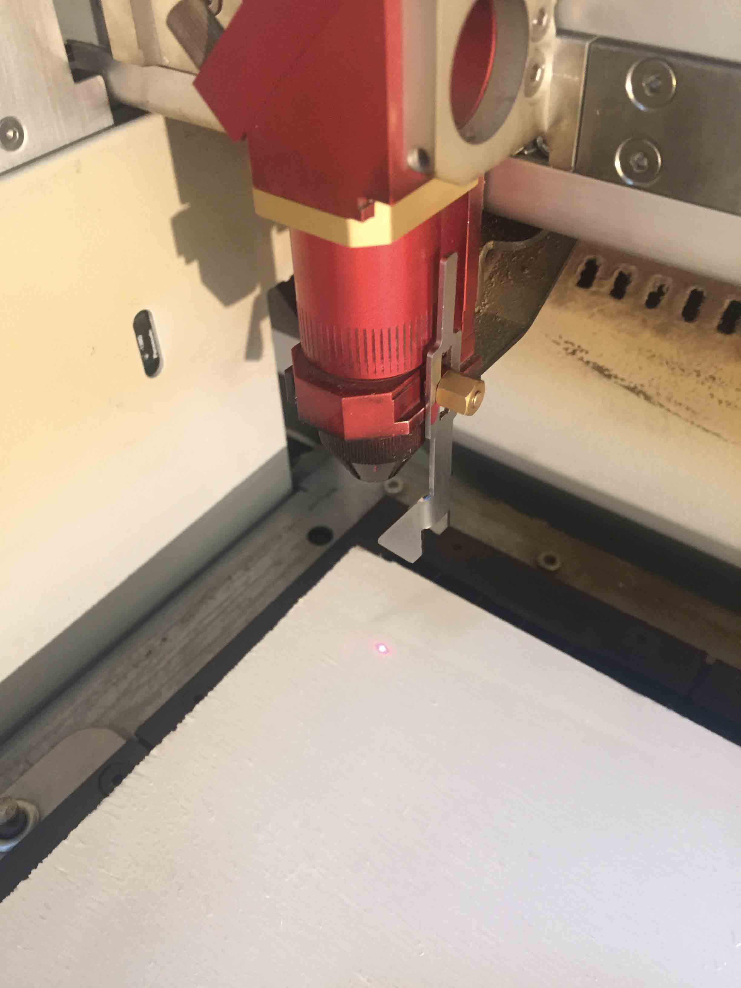
Before to send my work I had to bring on focus the laser. With a focus tool I move up the work station until it doesn't fall down.
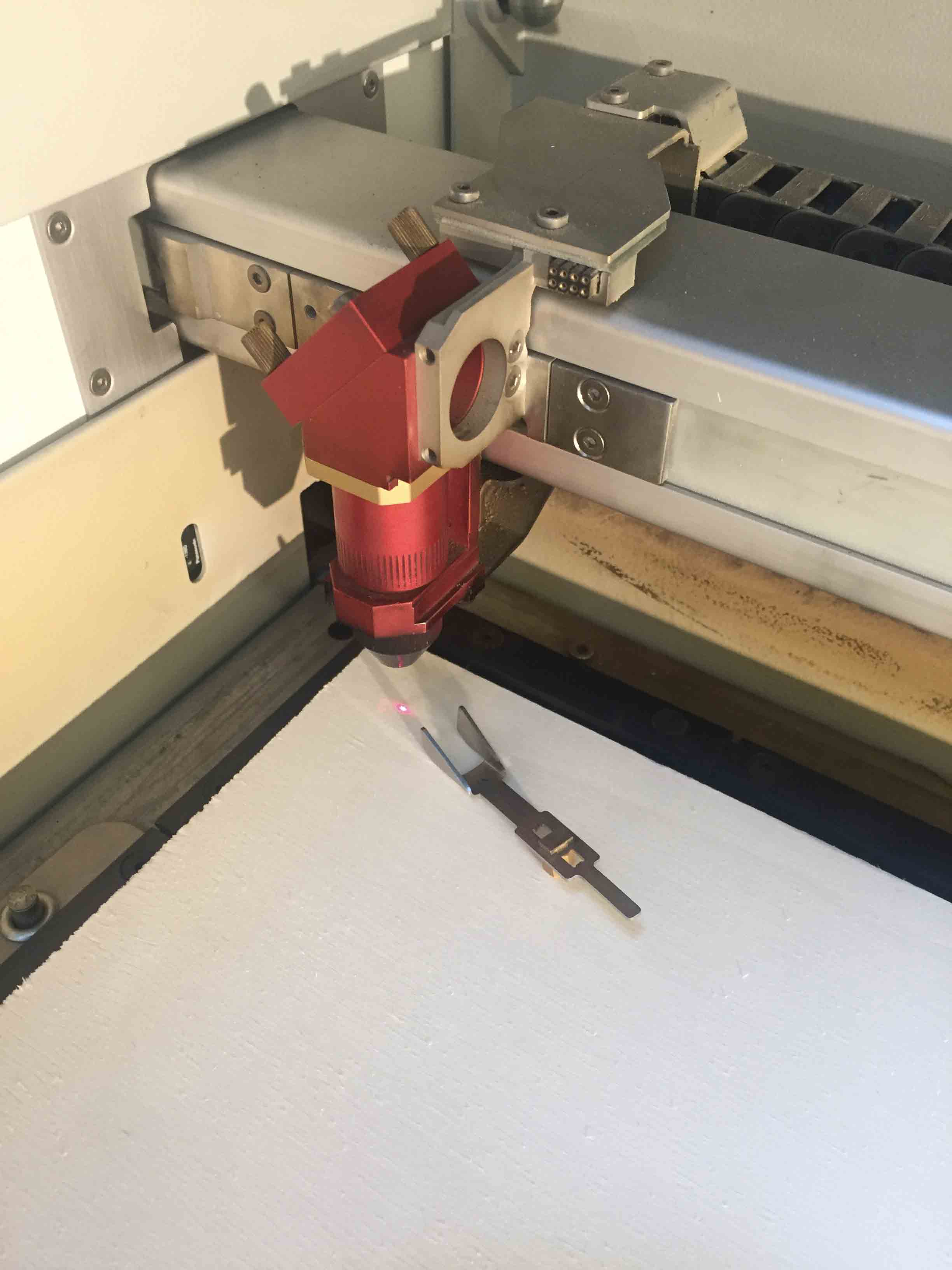
The laser can start to cut now. This is the first attempt and it doesn't work because I haven't added the kerf value.
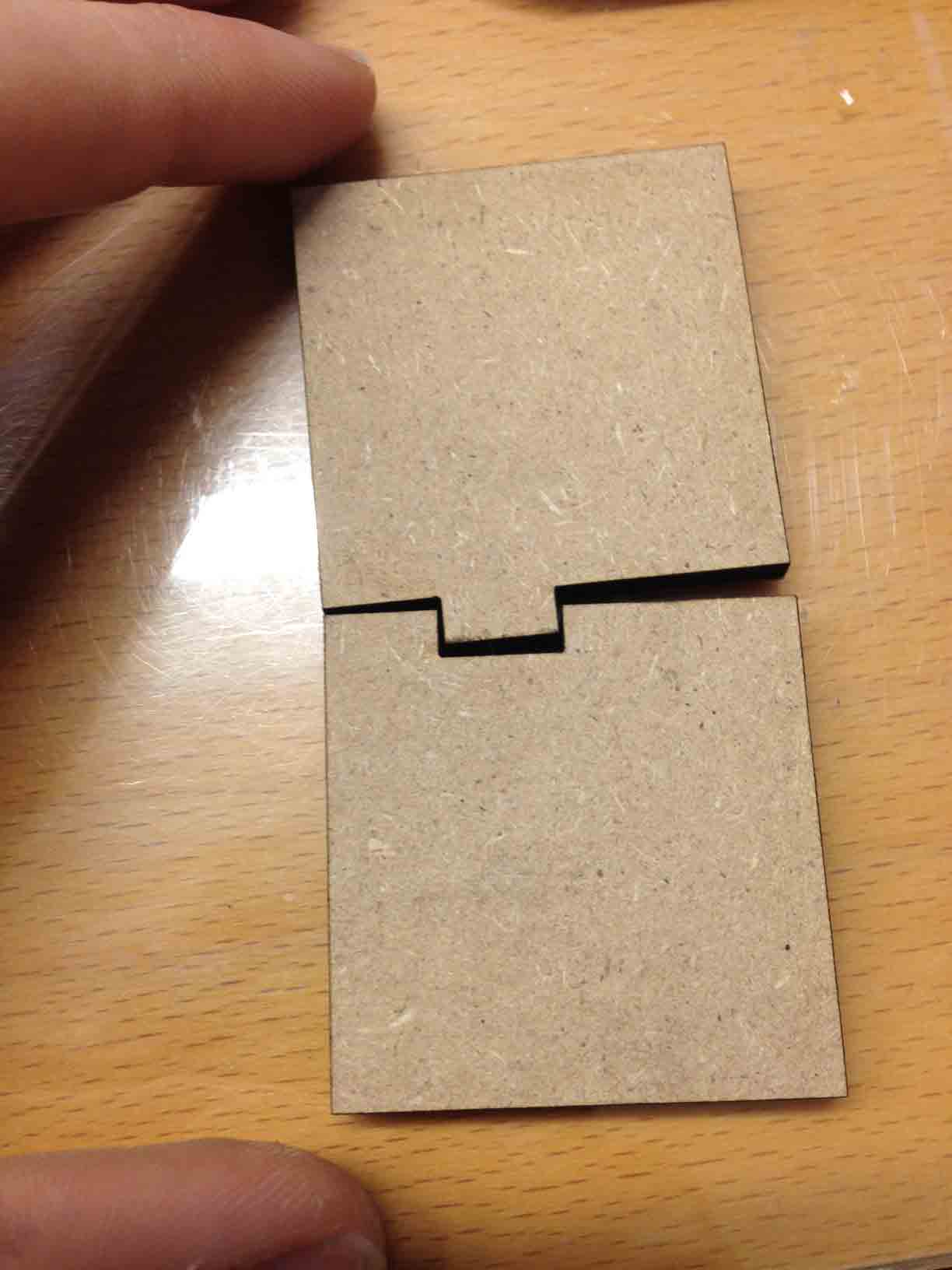
Second attempt works because I have changed kerf value (0,1mm) on my parametric sketch adding kerf value for male component and substracting kerf for female component. I have tried again to cut it and now it works.
Now I have changed material. I have used my plywood table for make a new test with kerf value. I have tried to use the same setting that we have found in group work, but it doesn't works. In this case kerf value was 0,05mm.

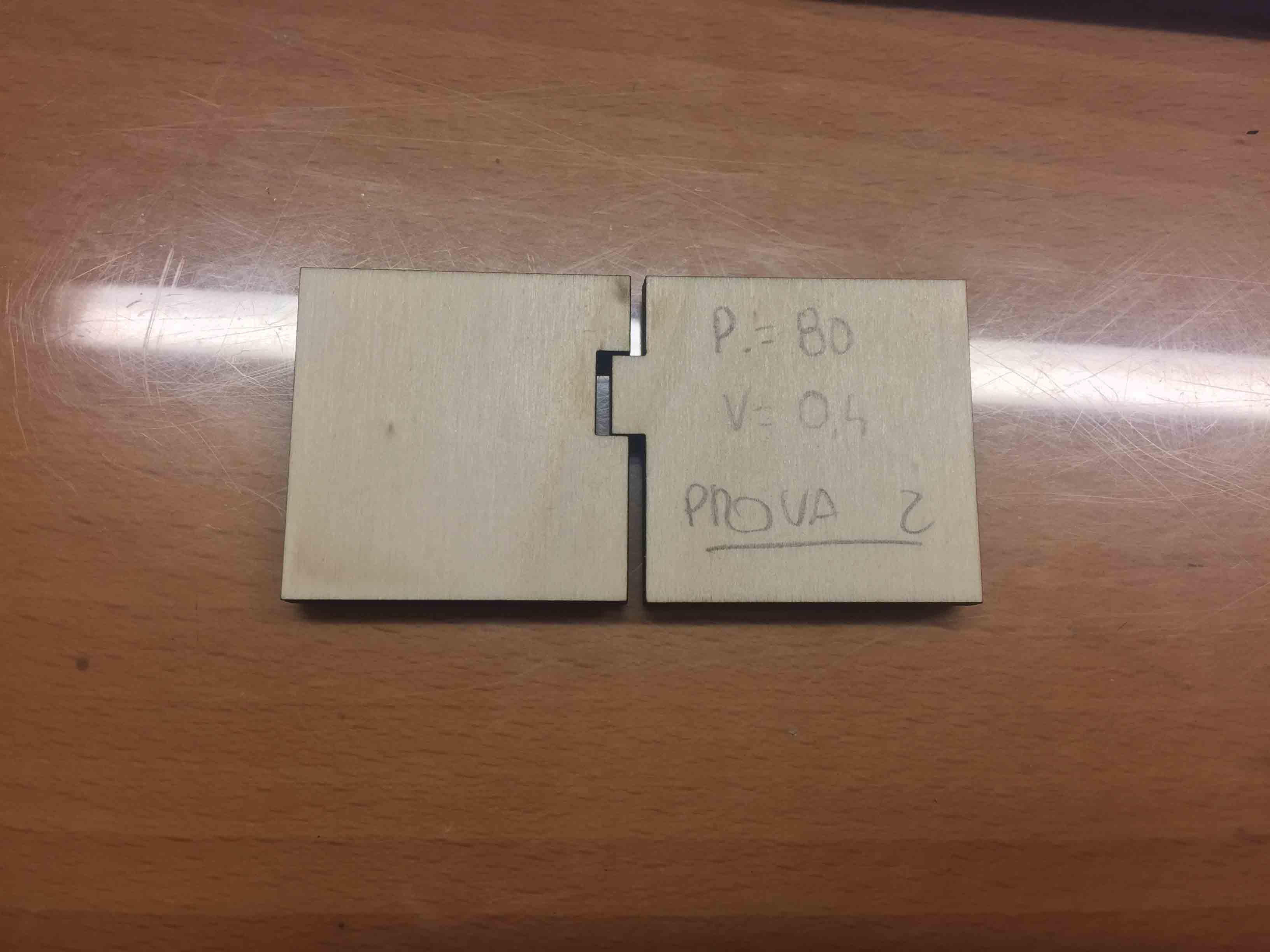
I have done another attempt changing laser power 80, speed 0,4 and kerf 0,02mm. It doesn't work yet.
I have done a lot of attempt, most of all using a random value. This is because each plywood table had different features, so it was impossible find perfect kerf value. At the begin I have thought that the problem was in my parametric sketch, but it wasn't.
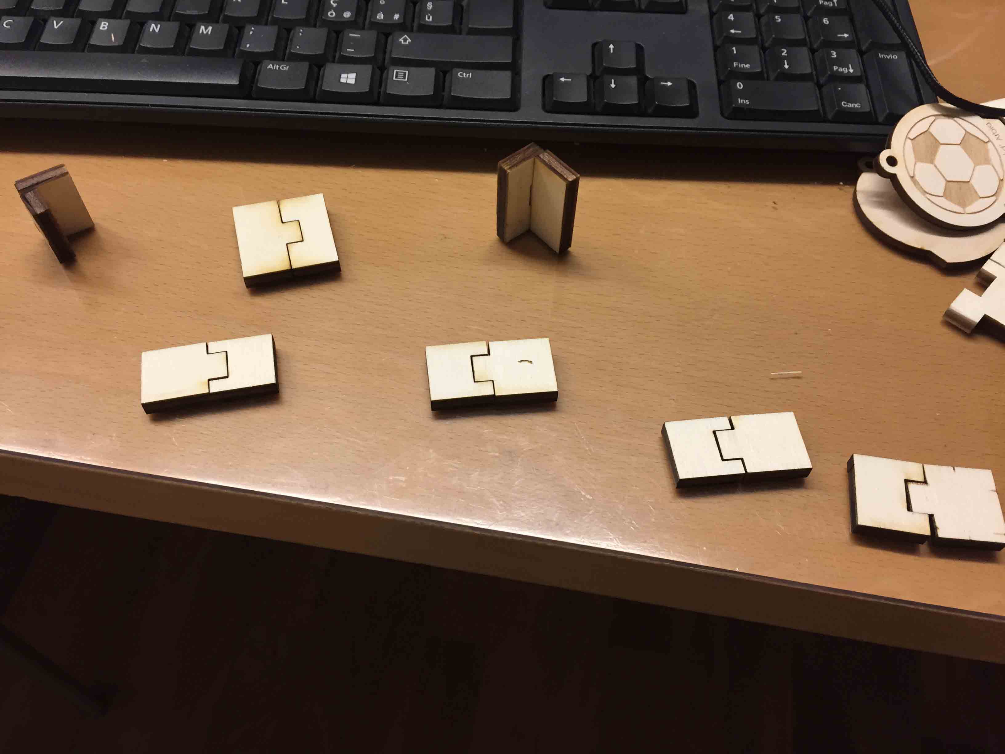
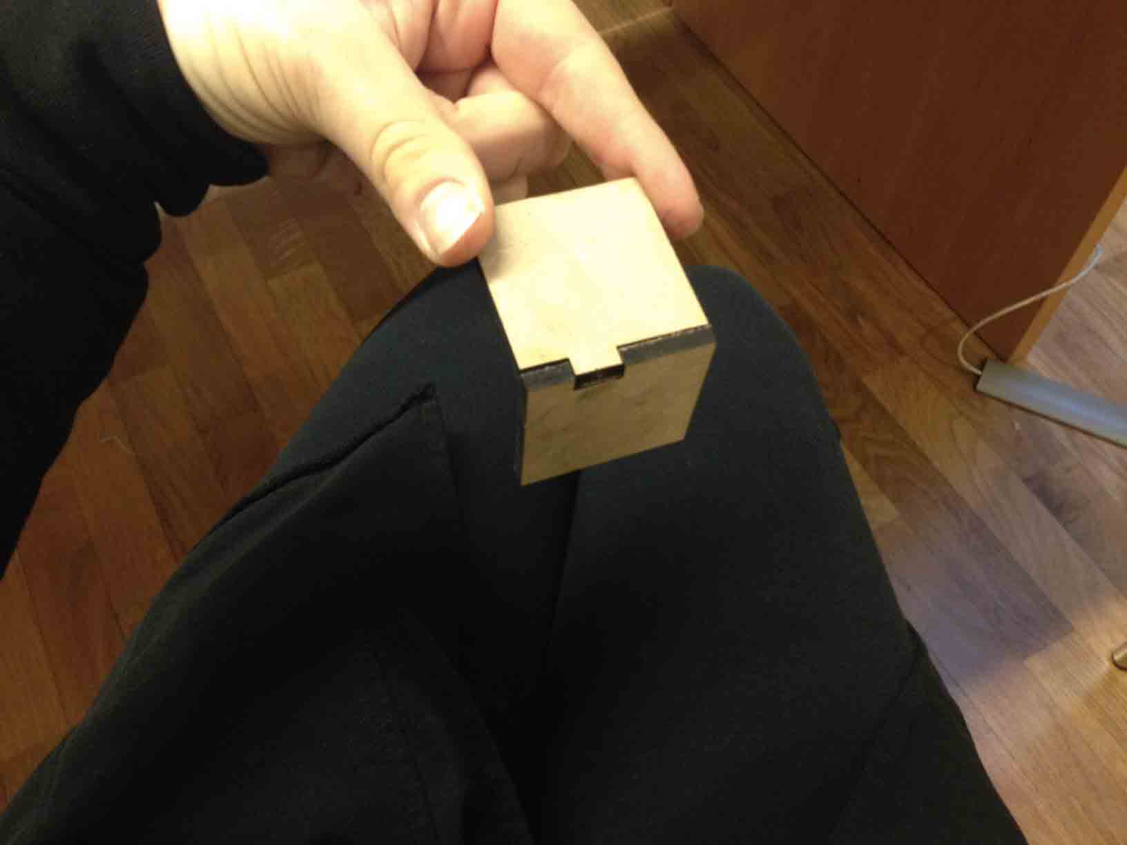
So I have cut a lot of joint and finally my kerf value was 0,1mm with power 80 and speed 0,4.
I have cut my sketch with this value and finally, after an entire day of trials, my joints works! This is the result.
DOWNLOAD
This week was pretty fun, still pretty hard. Figure out how to find best kerf value and doing a parametric model was exhausting.
Work with laser cutter was fun and interesting. During this months I want to do more practise with this machine.
You can find all files here.

This work is licensed under aCreative Commons Attribution - ShareAlike 4.0 International License.