Introduction
This is the final week for machine building, so I'm focusing on the functionality of the motors.STEPPER MOTORS
I have tried to regulate stepper motors for our machine to obtain a linear movement. As you can see in week 10 documentation, I have done a lot of attempts changing power on stepper driver installed on CNC shield.
To modify the power I have screwed and unscrewed the bolt on it and to test if the movement was linear. I couldn't get the right setting, so I have checked the solder. They were weak so I have re-solder it and then it work correctly.
So I add the Y axis on CNC shield to move two motors together. It had the same problem of the first one so I have checked solder on it also. When I was checking the solder I thought to solder wires in the same order of the first one and at this point I have understand an important thing. Wires order isn’t casual!
Now motors works correctly. All my stepper had a linear movement. I’ve tried to send a G-Code line to test them. I connected the CNC shield to my pc and GRBL interface gave me back some errors. So I have looking what that code means and I have found answers on GRBL documentation. Particularly I got this errors:
ERROR 3: Grbl '$' system command was not recognized or supported.
I had this error when some cable weren't connect correctly so the communication was interrupted.
ERROR 20: Unsupported or invalid g-code command found in block.
I had this error for a very stupid mistake. I wanted to write G0 command but I wrote GO.
ERROR 22: Feed rate has not yet been set or is undefined.
G-code needs a feed rate value. This value changing speed movement. For example a F60 means 60mm/minute. Is important setting it especially for G1 command because I used it for linear and precise movement.
I paid attention to avoid this mistakes.
GRBL CONFIGURATION
After that I setted GRBL. To understand which were settings that I needed to change, I have read GRBL documentation (link). In this documentation you can found answers for all your question. Opening the serial monitor from Arduino IDE, if you typed $$ command you can see the settings.
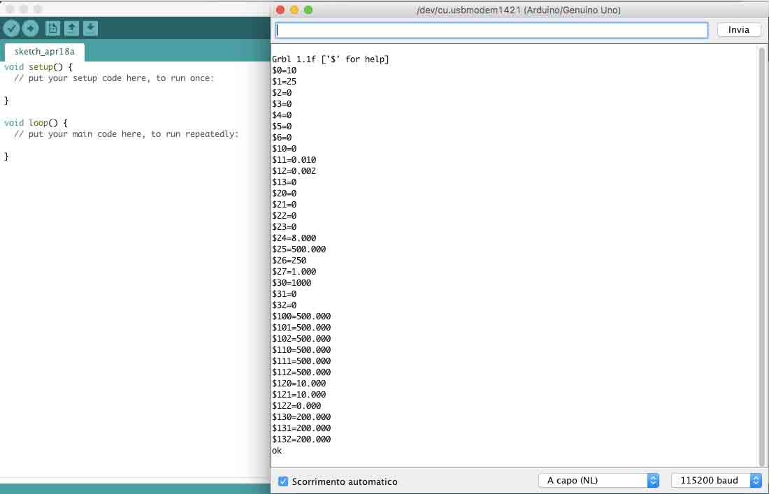
The most important settings here are:
$100
$101
$102
Here I set step/mm rate for X, Y and Z.
To find the right values I have done some tests sending some G-Code lines alike our machine movements. Other important settings are, for example,
$110, $111, $112 ([X,Y,Z] Max rate, mm/min) to sets the maximum rate each axis can move and $120, $121, $122 ([X,Y,Z] Acceleration, mm/sec^2)
to sets the axes acceleration parameters in mm/second/second.There are other settings that you can modify (as you can see in the picture above), but in my case I didn't need to change it.
MOTORS
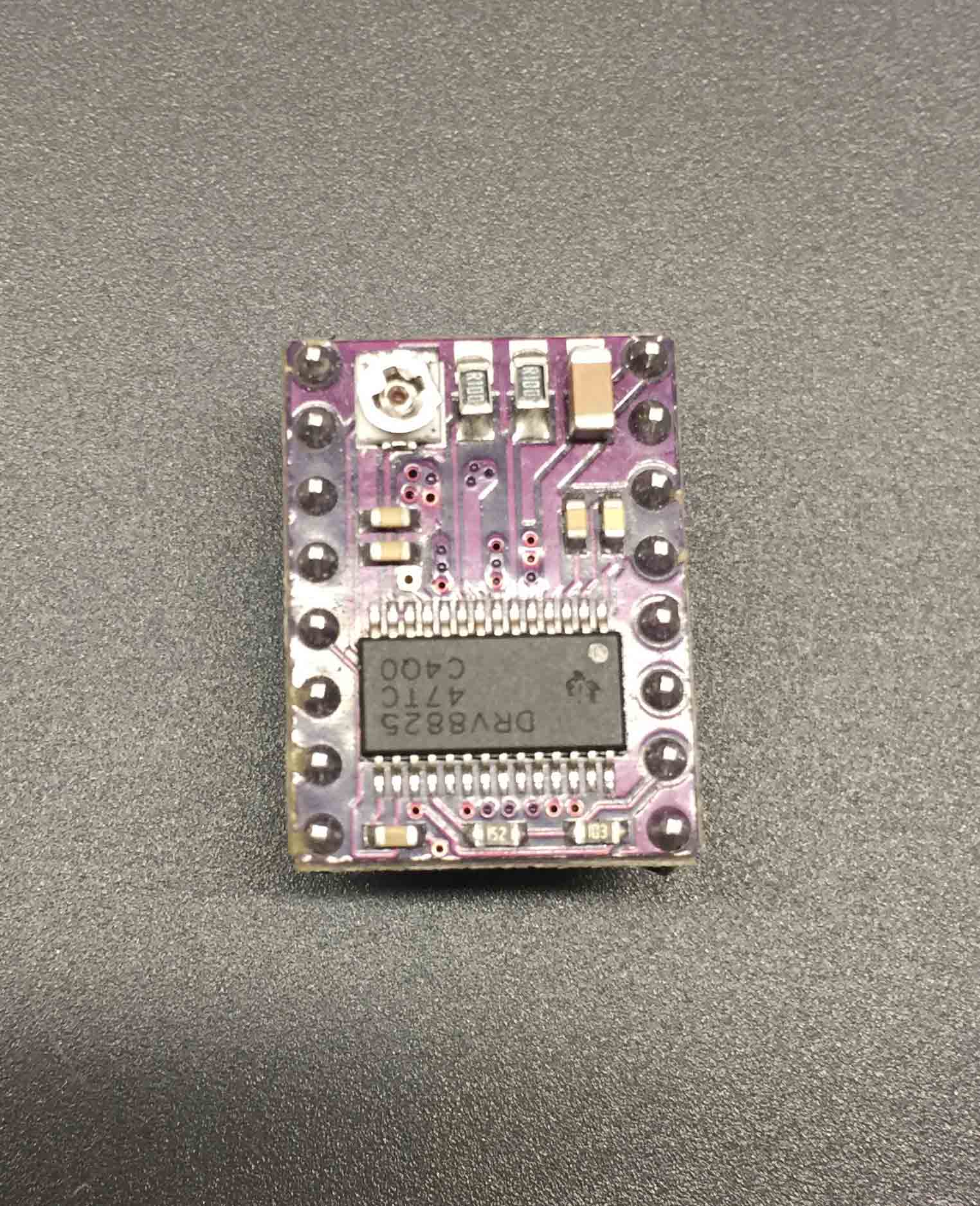
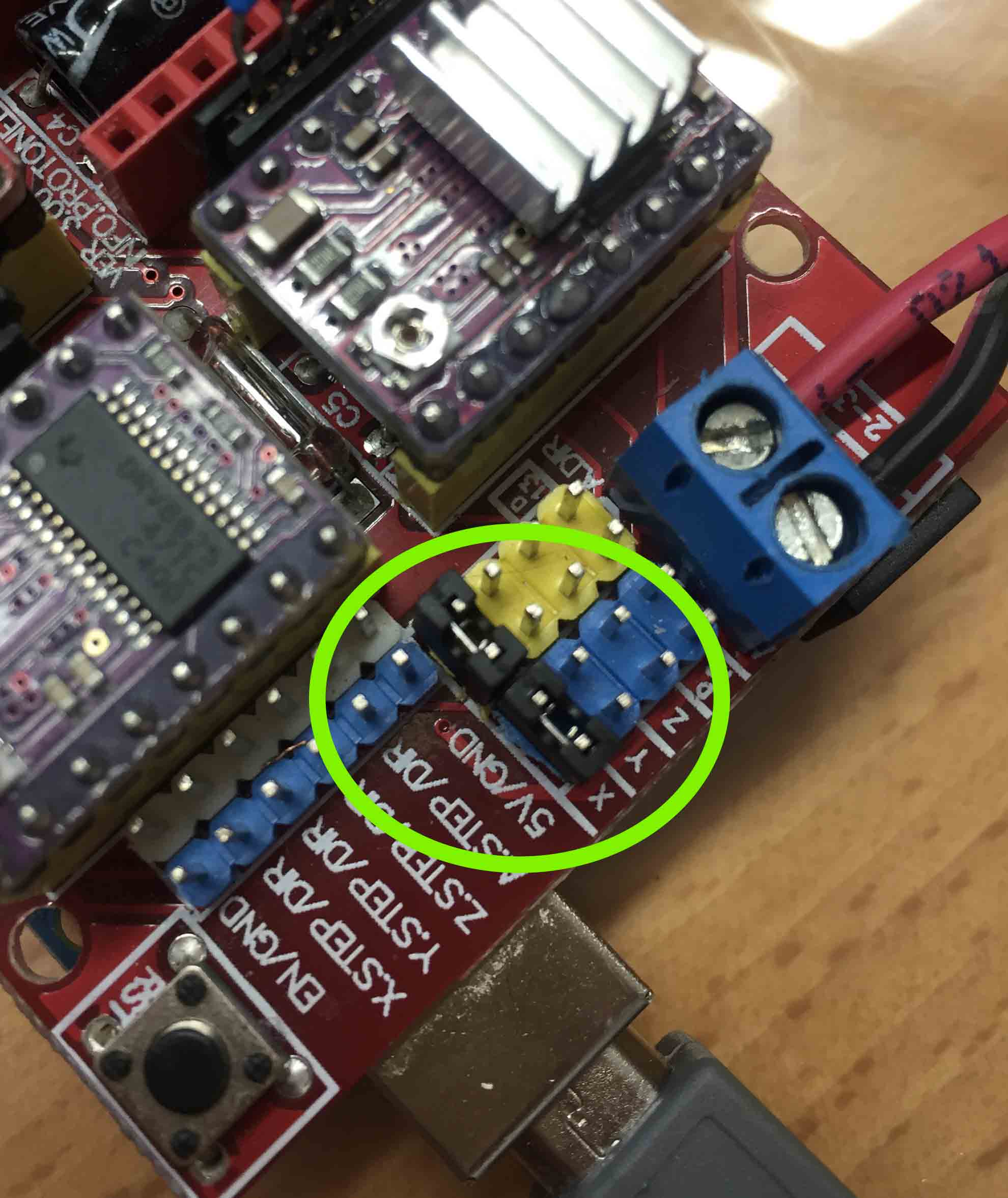
For our machine we need to move 4 steppers motors, so on our CNC shield we have connected 4 drivers. The problem was that latest version of GRBL can support only 3 axises not 4. I have looking for a solution and on this tutorial. On CNC I can clone a movement of an axis. I have followed this tutorial adding a jumper on the X axis.
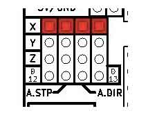
I have decided to clone this one because the movement of rolling pin and wooden pole are the same. I connected CNC shield at my computer and I have send a g-code line to test it.
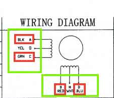
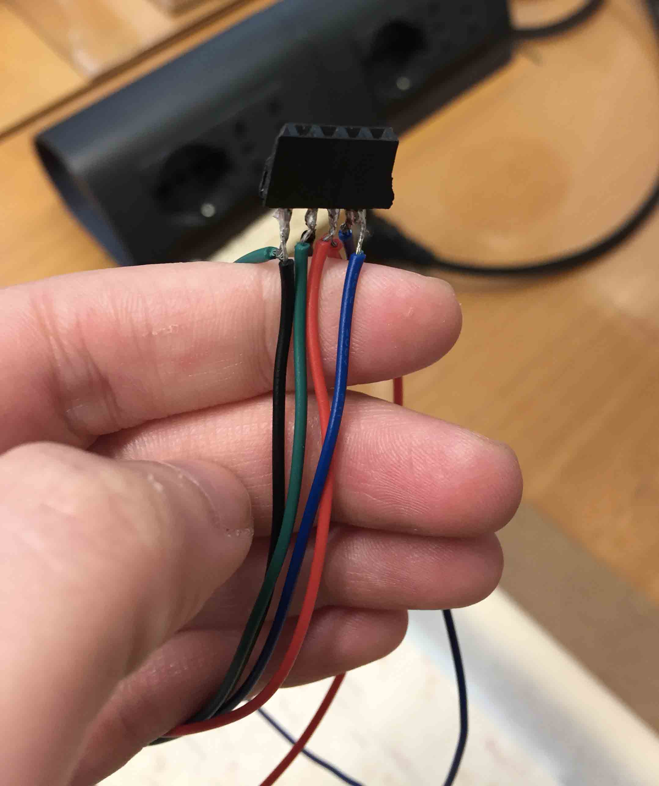
t didn’t work yet. I have asked help to my colleagues and Pietro suggested me a little trick. As I have told before, my rolling pin and wood rolls have the same movements, but two turn in clockwise direction and one in anti-clockwise direction, so I have settled two motors on the same female connector for X axises.
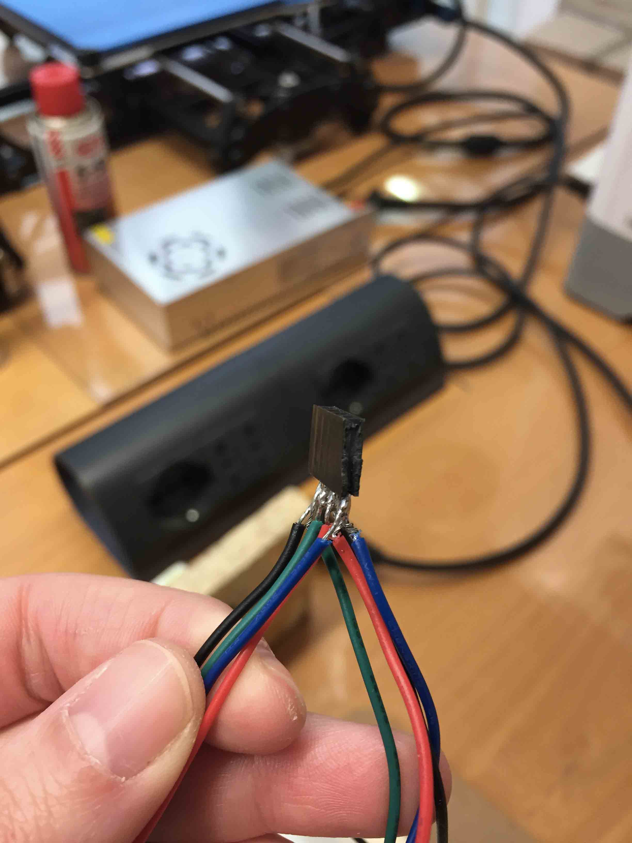
To create a clockwise and anti-clockwise movement, I have solder it changing black and green position. In this way I switched the wire movement. With this trick I was able to use 4 motors on a CNC shield. I know that it isn’t the proper way, but they works.
To see the results, check this link: WEEK 10 DOCUMENTATION SILVIA'S DOCUMENTATION GROUP PAGE BISCUIboT

This work is licensed under aCreative Commons Attribution - ShareAlike 4.0 International License.