Week 6
Electronics Design
Objectives
Learning Outcomes
Have I ...
Documentation
For this assignment, I redraw a hello-world board, adding a button and LED and its current-limiting resistor.
Something that I wanted to do is redraw Fabduino, I did it! Also I design my mainboard of my juggling club. Which has all paths, pins, regulator voltage from 5VDC to 3.7VDC and all necessary to be my juggling club mainboard.
JhonDuino
Using Eagle I redesign fabduino. I did it more compact and smaller. Measures approx 35mm x 35mm.
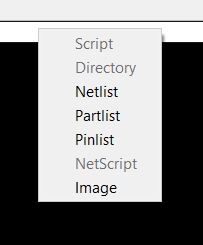
To export monochrome pic of your design, write "exp" coomand and click on "Image". Set the file to save, check Monochrome box, 2400 pixeles at most. Check Window box. That is all, export your .png file.
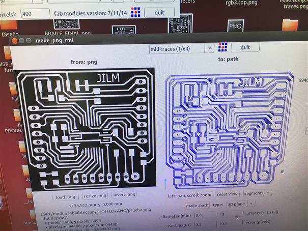
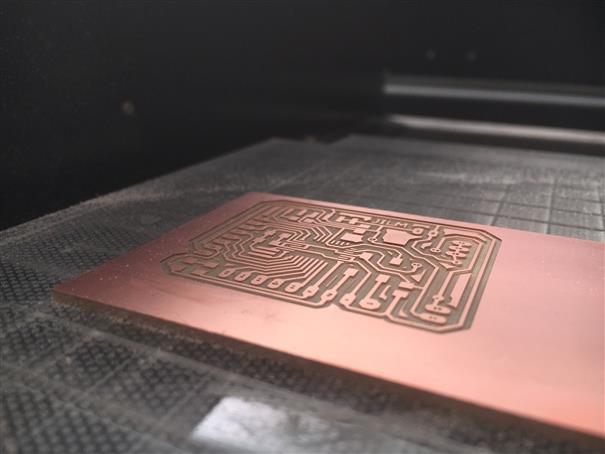
Use MDX-20 to mill the file. Enter to terminal ubuntu, write "sudo fab", enter password. Select .png file and Roland Modela MDX-20. Load your image, choose 1/64 mill at top. Offset: 3, Error(pixels): 0.1 and rest same values. Click on "Make path" and just wait. Change speed from 4 to 2 or 3 mm/s, using this parameter milling tool is being protected.
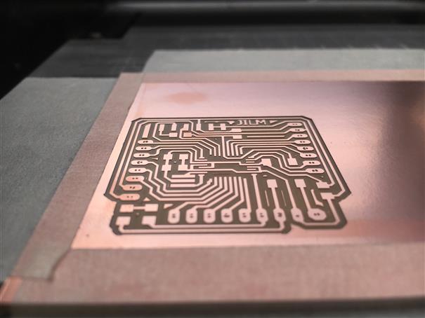
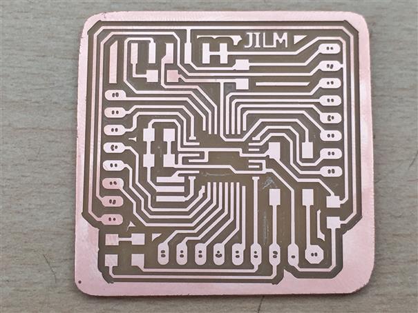
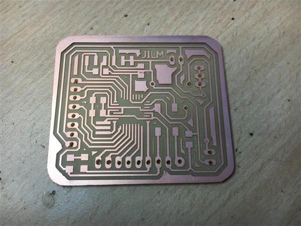
Finally, I have my Jhonduino. It is so beatiful! But, there was a mistake I forget a path. To solve this mistake using a cable I did a bridge. Immediately, my files were corrected.
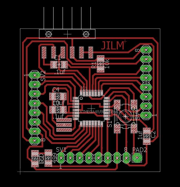
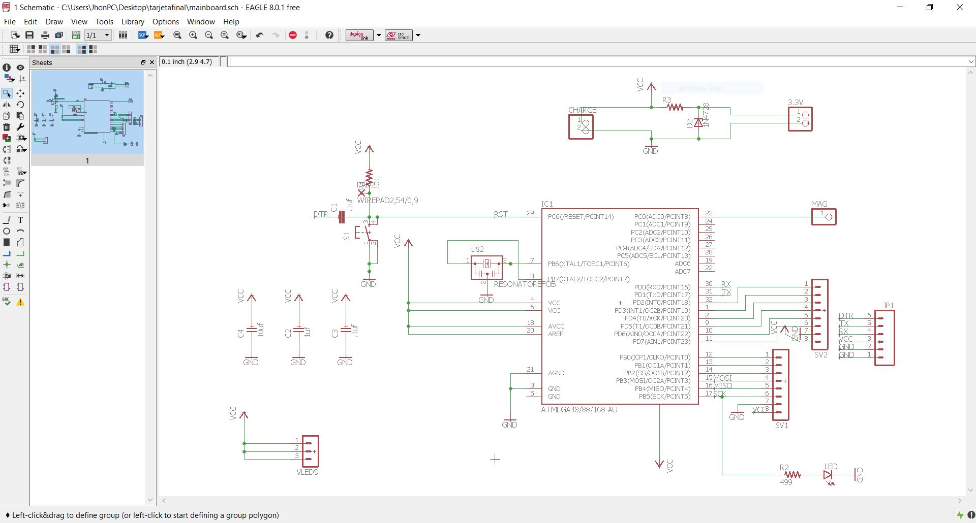
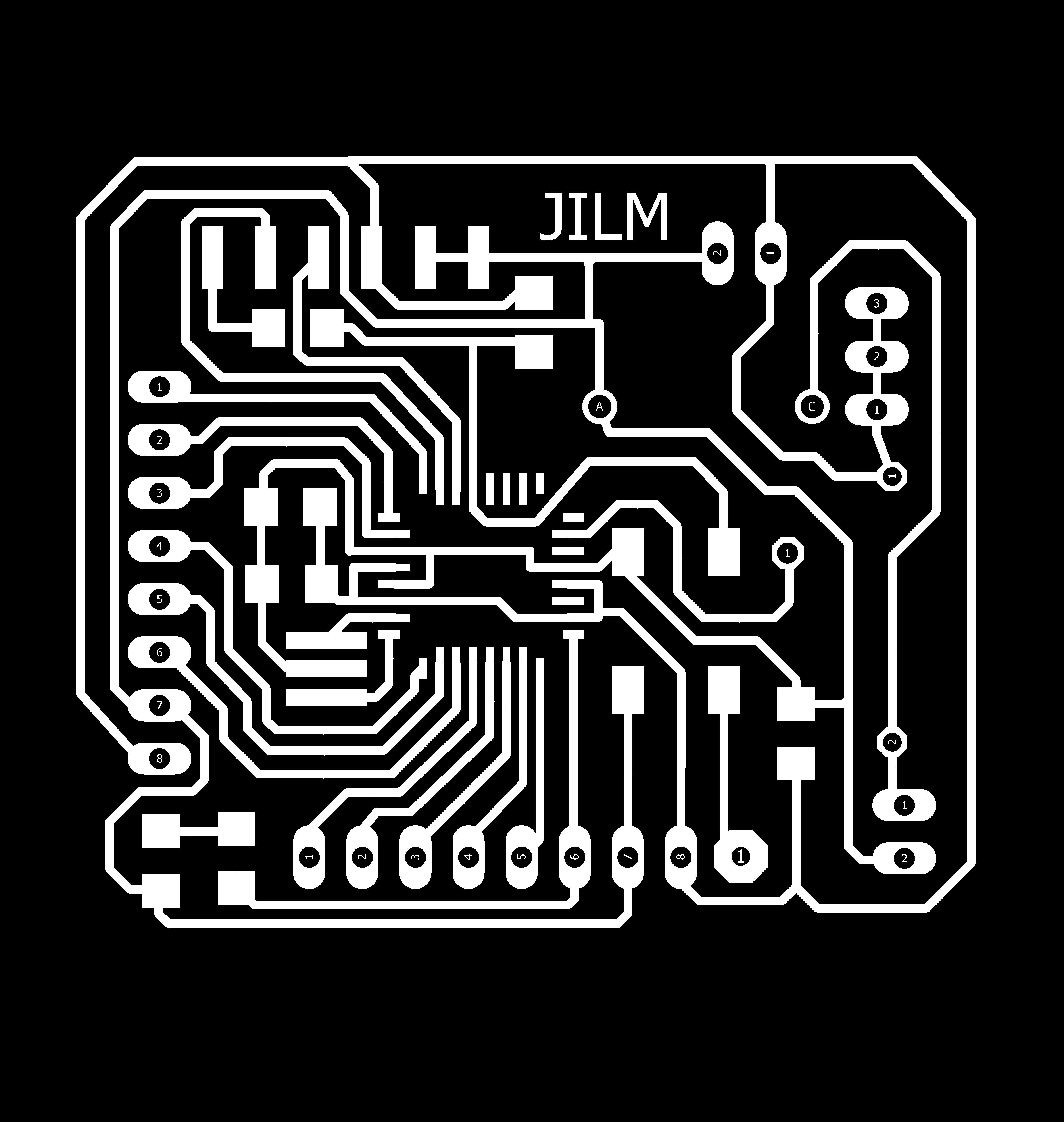
MainBoard Juggling Club
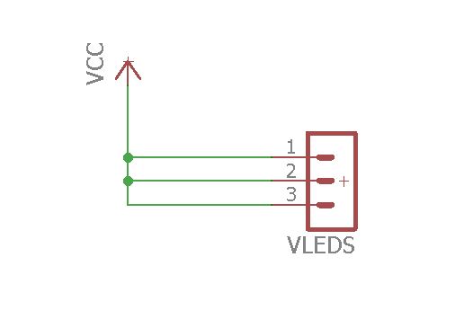
Using Eagle I redesign Jhonduino to have mainboard. This one only uses the necessary pins. I add three VDC pins to supply LED RGB boards.
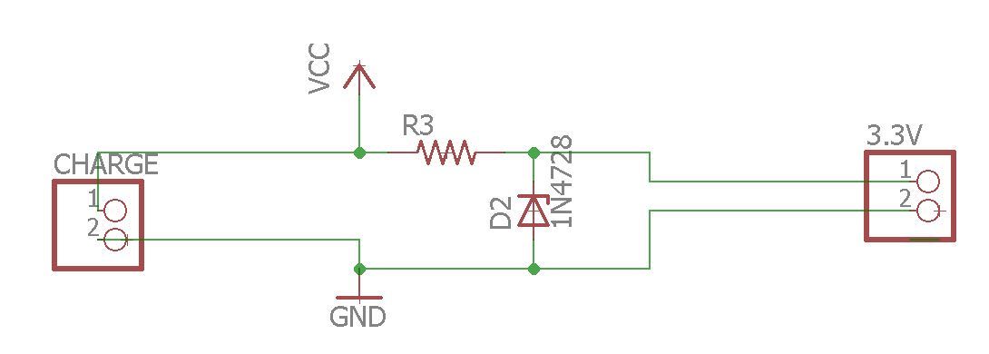
It has a voltage regulator from 3.8 volts of battery to 3.3 volts to supply magnet sensor board. For this has a zener diode (3.3volts) and a limiting resistance of 10ohms - 1/2W.
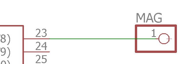
Also, it has a pin to connect magnetic sensor signal out.
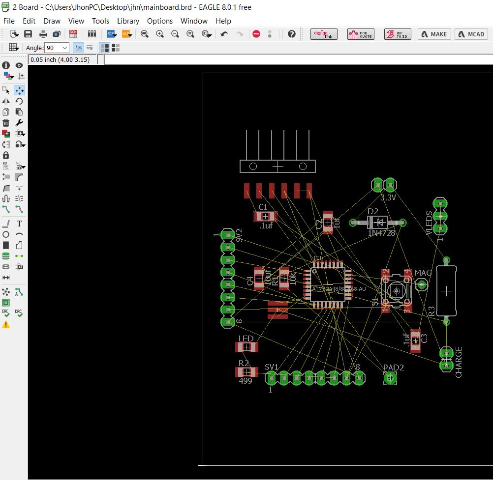
When schematic design is finished, let to design our board.
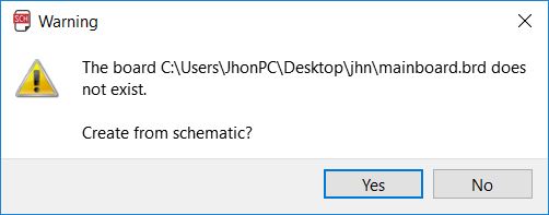
Click on this icon, it is on top-left. On the next window, the software asks if your new board is based on currently schematic, so that is ok. Click on "Yes".

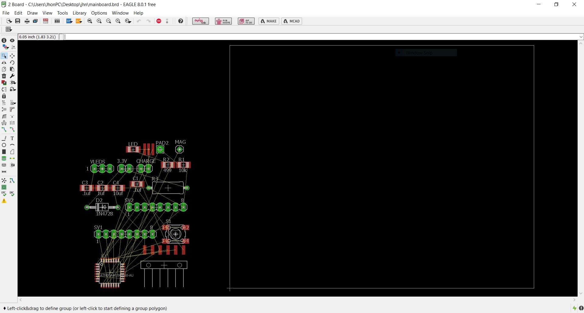
In the next window we see our components joined with yellow lines that are our connections.
Now, using "move tool" let to place our components inside the white line. A tip I can give you is to place components based in schematic order.
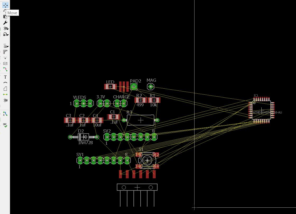
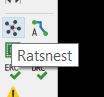
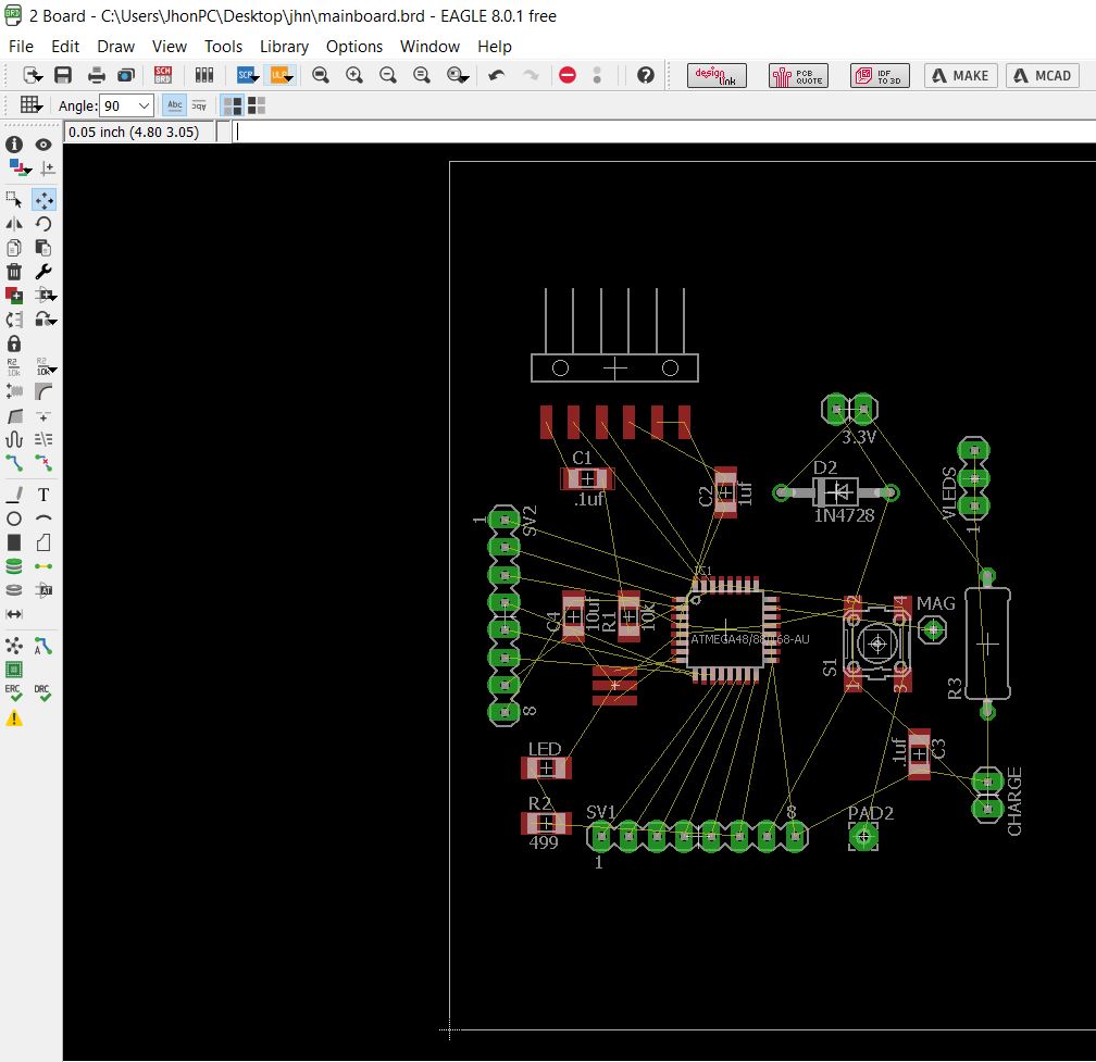
There is a tool that I like a lot from my university studies. It is "Ratsnest", this reduces the connections "yellow lines" that are repeated simplifying our design. Just click on and see the magic.
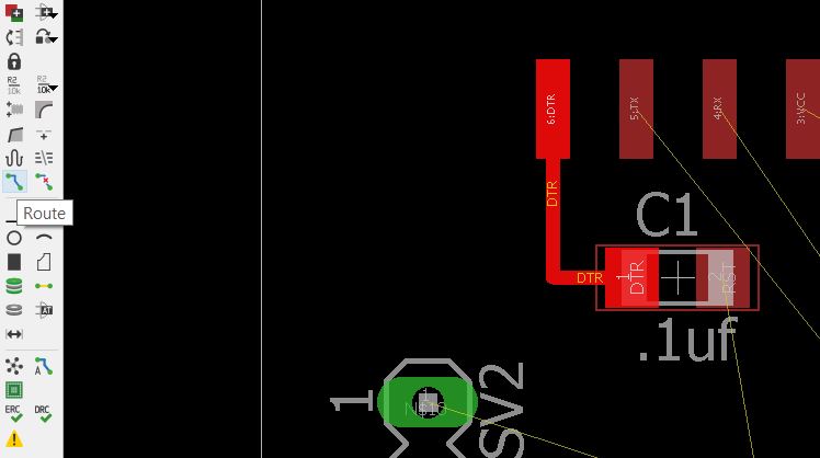
Then let to create our paths using "Router" tool. Click on where yellow line starts and draw.
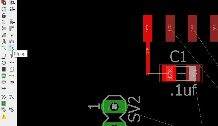
If you need to redraw a path either because you failed or another reason. Use "Ripup" tool.
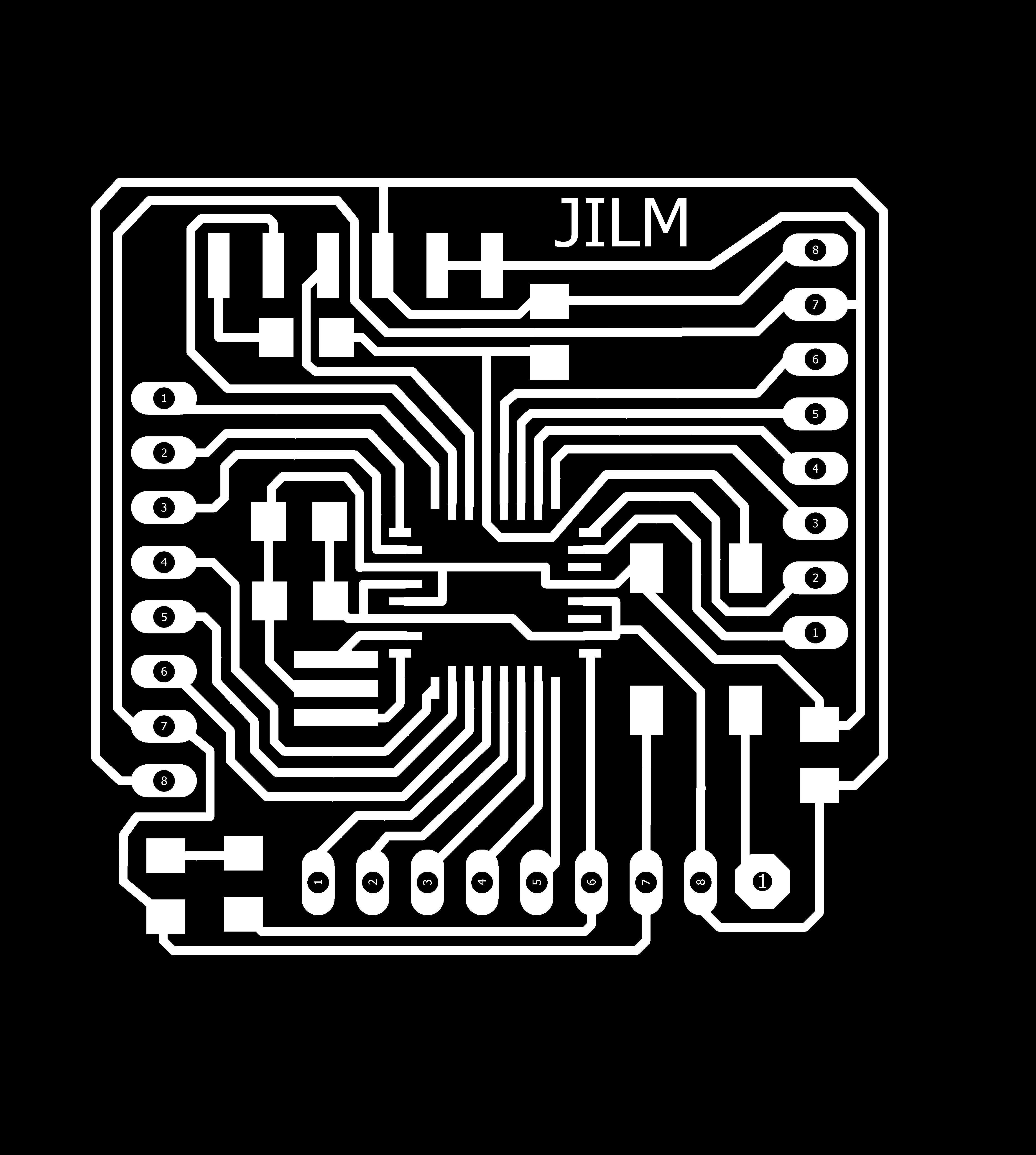
Then , we proceed to export .png file to mill in Modela.
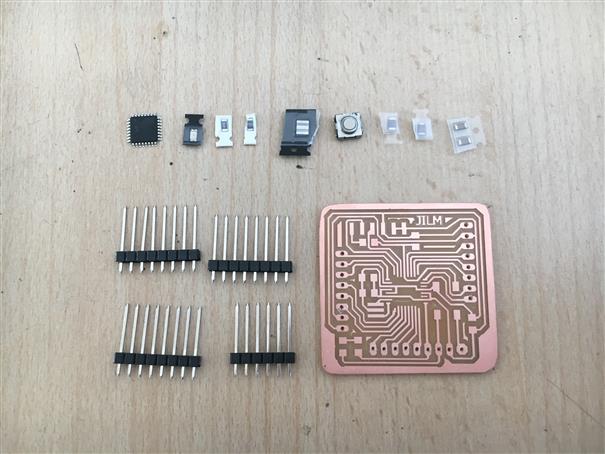
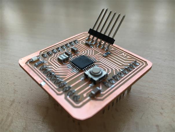
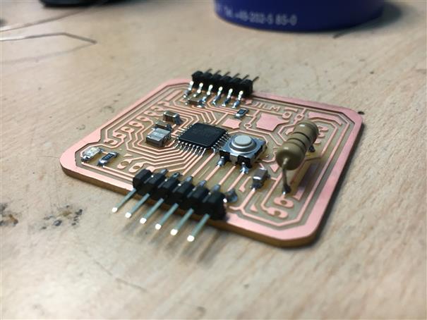
Finally, after weld electronics components.