Week 3
Computer - Controlled Cutting
Objectives
Learning Outcomes
Have I ...
Documentation
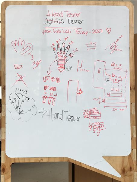
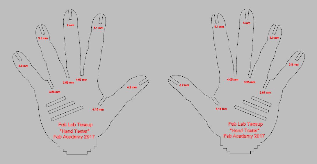
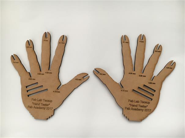
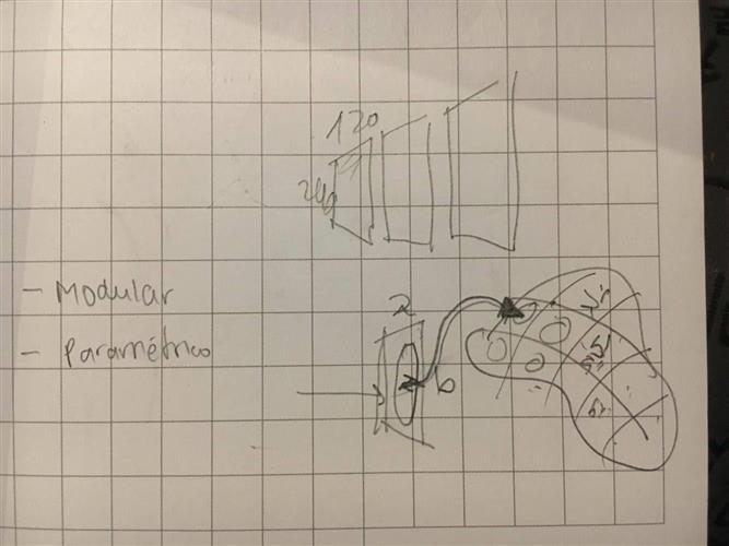
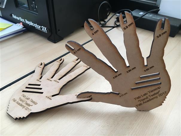
We had a meeting group where our final result were a "Hand Tester". Each finger has different measure.
Additionally. I desing a parametric pieces, my idea is that joining a lot of them could have like a flexible loom.
Design
As group we decided to download a hand shape photo and share us. Using Rhino I did my design. "Sketch" tool is good to have the sape. Then, using lines did the rest. "Text object" tool for letters.
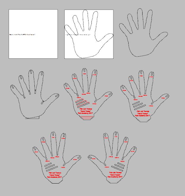
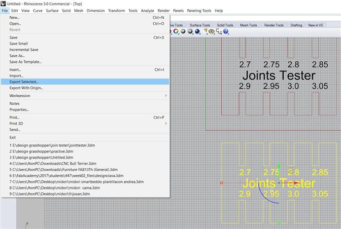
To export .dxf files. Select, what you want, click on "File", click on "Exported Selected" and choose .dxf extension.
Laser Cutting
Choose your material, Epilog laser could cut MDF , acrylic, leather, paperboard and engrave the same adding metals, glass. It is recomendable not cut PVC pipe, the smoke it releases is harmful. In Epilog laser, when is cutting there is 3 parameters to set up: Power [0 - 100%], Speed[0 - 100%] and Frecuency [0 - 5000], when is engrave just 2, speed and power .
Place the material on left-top corner, press "Start Job", keep eye on.
Modular vs Parametric
In this part, I has a confusion about what is PARAMETRIC and what is MODULAR. One Saturday, I met Benito Juarez, Director of FabLab Lima, on FabLab Tecsup, he was working on a project with young people from the Peruvian jungle. I asked him about modular and parametric.
He made me an example. A wall modular is a wall with the same measures or standar that are repeated to complete or fill some space. A wall parametric is a wall that changes its measurements according to the surface that has to be filled or covered.
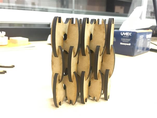
Modular Design
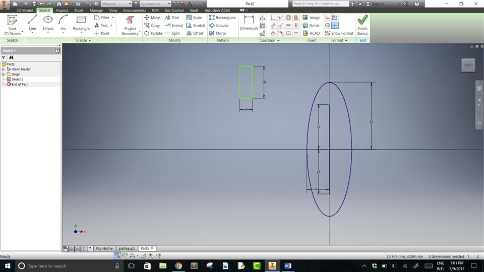
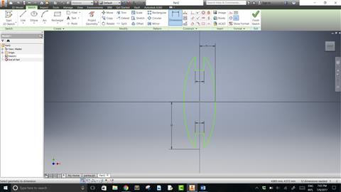
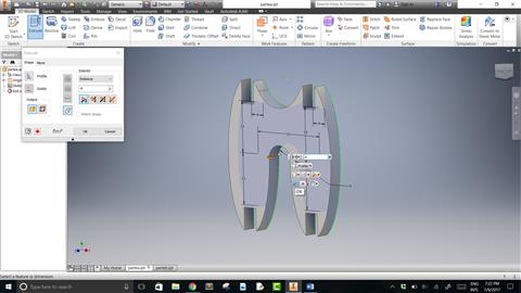
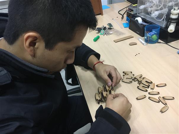
I did a wall composed of two pieces, I used Inventor to do my design. Piece one is called "H" and the other "extreme"


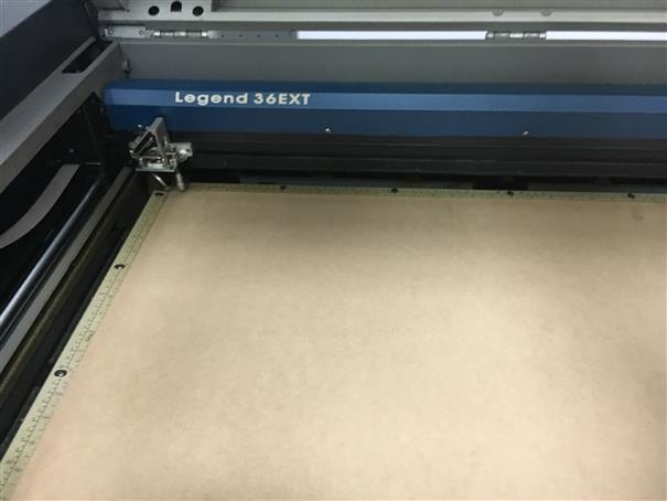
USING EPILOG LASER LEGEND 36EXT
Once I had my design, I used Laser cutting machine, FabLab Tecsup has a Epilog Laser Legend 36EXT, to cut some pieces and build a wall. I export a .dxf file of inventor. Steps to cut in laser cutting machine.
1.Open Corel Draw 2.Import your .dxf file, there will appear your pieces.
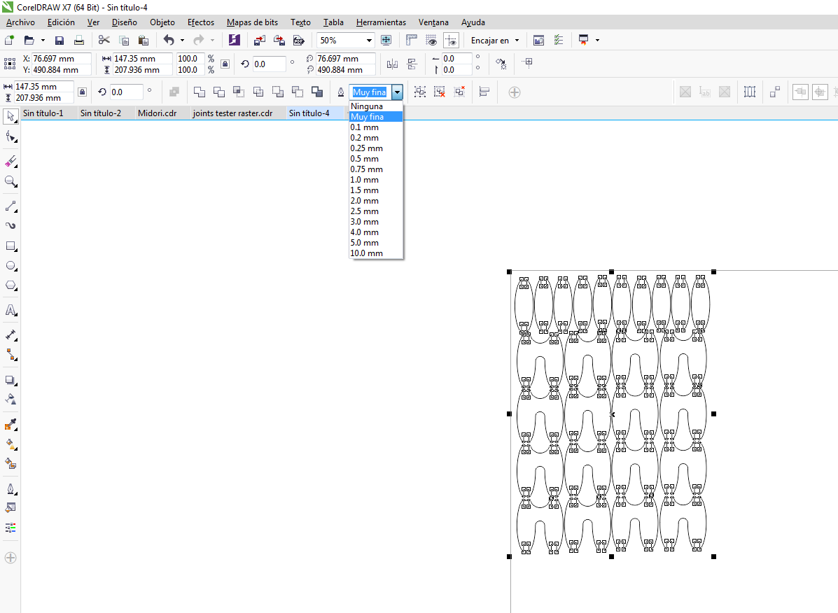
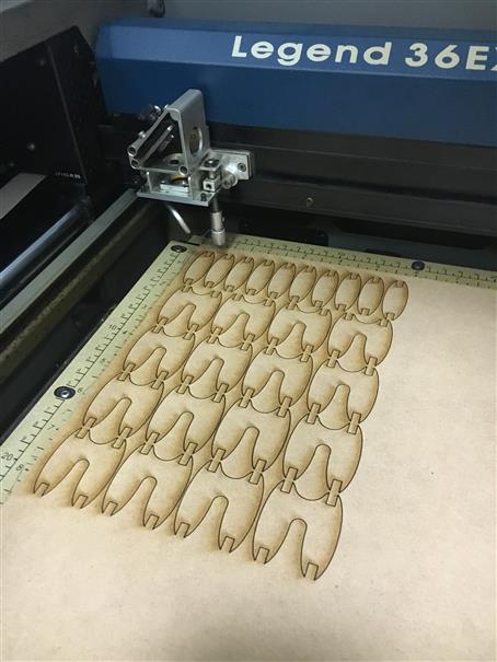
3.Now, copy and page those pieces, a wall of 3 row x 3 column needs 6 pairs of "H" and 3 pairs of "extreme". All lines to be cutting have to be selected as "Muy fina" or "Hair line", if there are not like that, there won't be cutting.
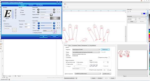
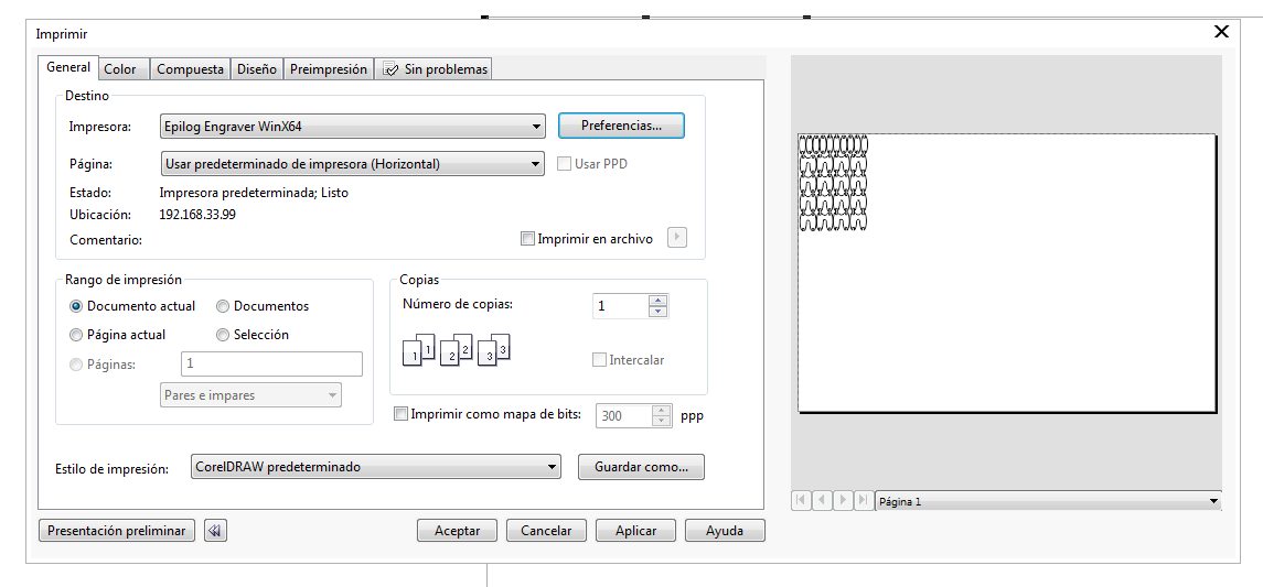
4.Select lines to be cutting and press "Ctrl + P", window on left side will appear and click on "preferences". 5.On window right side let to configurate parameters. In "Options" tick "Auto focus" (it means laser machine going to detect material thickness using a pin on his head). In "Job Type" tick "Vector" (Raster: to engrave pictures / Vector: to cut / Combined: to cut and engrave). In "Piece size(mm)" is the cutting area " Horizontal: 900mm | Vertical: 600mm". In "Vector Setting" there are 3 parameters "Speed" set at "18%", "Power" set at "92%" and "Freq.(frequency)" set at "5000Hz". Those parameters (speed, power and freq.) are for MDF 4mm.
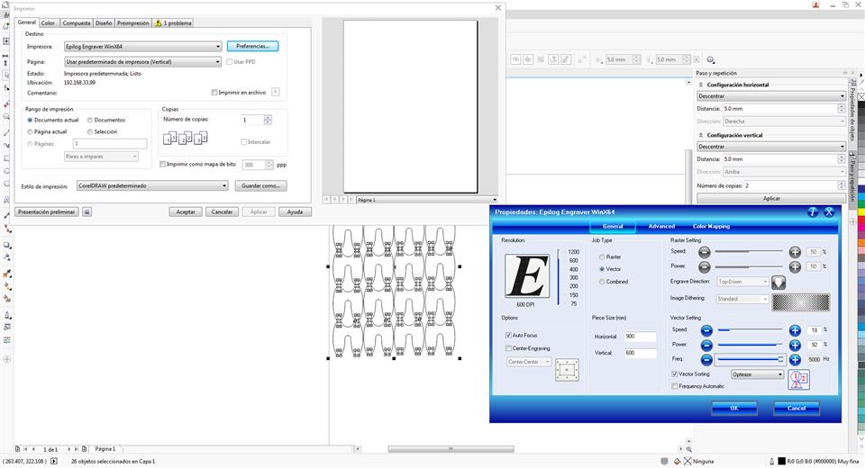
6.After setting parameters you can see a preview window and click on "Aplicar (apply)" and "Aceptar (accept)". Your work going to be send to laser cutting machine.
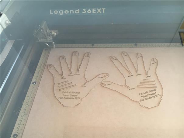
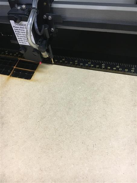
7.Then, place your material, in my case MDF 4mm on top-left corner and press green button "Start".
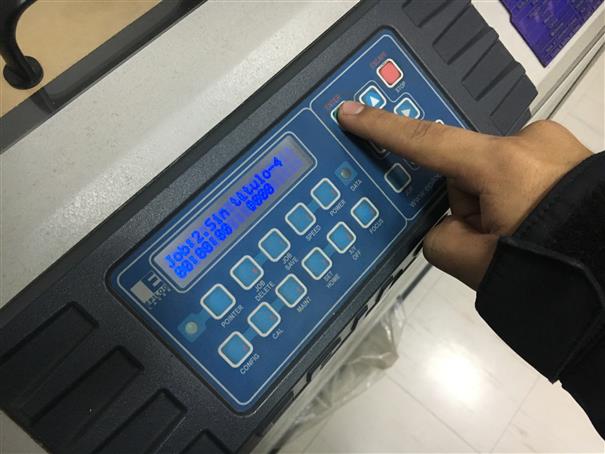
8.Laser cutting machine starts to cut.
Parametric Design
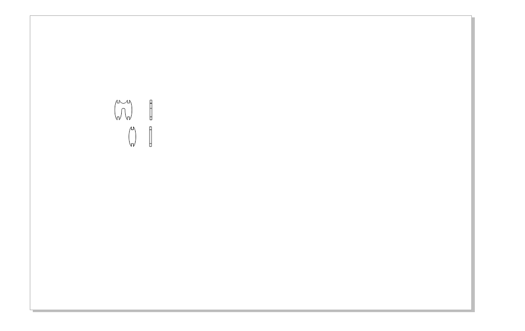
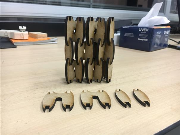
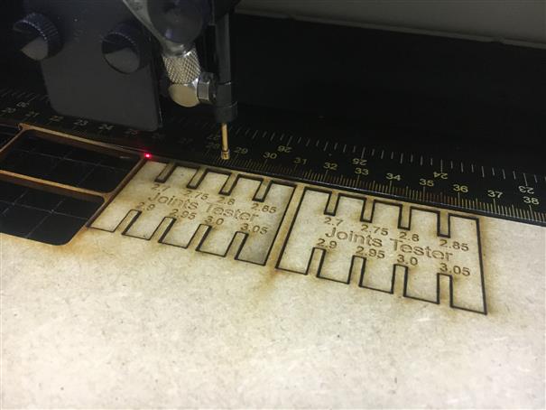
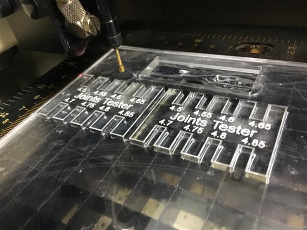
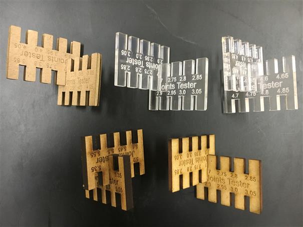
When we want to do a design using pressfit, do a material test is very important to have the exact measurement of the aperture. Sometimes the measurement is different to the thickness. For this, I design a joints tester using Rhinoceros and grasshopper in order to control the thickness value each time there is a different material. Using just a parameter the design changes allowing to have a design easily and quickly.
My first design is a joints tester using Rhinoceros. If I want to modify the thickness it is necessary to redesign.
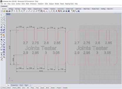
So, I decided to use Rhinoceros + Grasshopper to make a parametric joints tester.
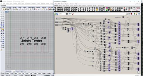
Those are the parameters to modify according you need.
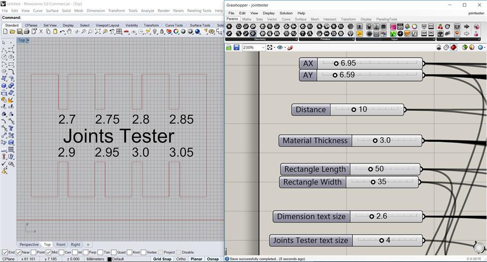
Parameters:
1. AX and AY: those are the coordinates when the design start 2. Distance: it is the depth of pressfit 3. Material Thickness: material thickness 4. Rectangle length: rectangle length 5. Rectangle width: rectangle width 6. Dimension text size: size of dimensions text 7. Joints Tester text size: size of "Joints Tester" text
In the following video you can see how to interact with the software.
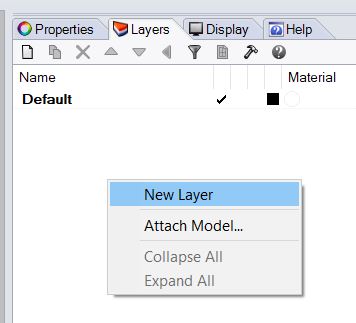
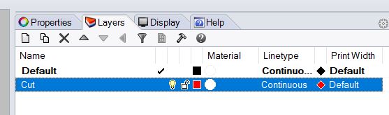
Once the lines is transfered from grasshopper to rhinoceros. Lets to add a new layer. Set the name as Cut and Red (R:255, G:0, B:0) color.
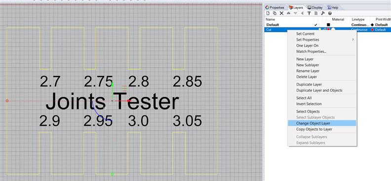
Select the lines and right click on cut layer, click on "Change Object Layer".
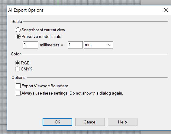
Immediately, click on File / Export Selected... Then, select .AI extension and mark the options like the pic. Check "Preserve model scale: 1milimeters = 1mm" and "Color:RGB" and OK.
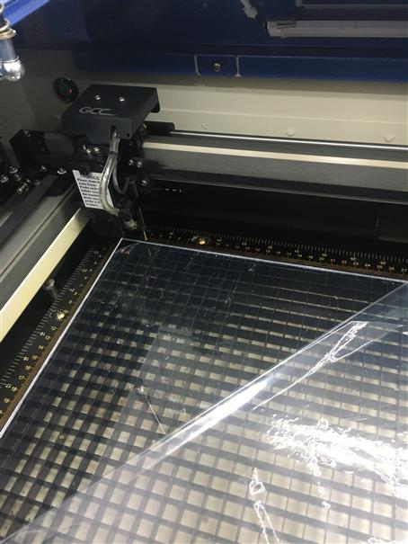
USING GCC LaserPro MG380 Hybrid
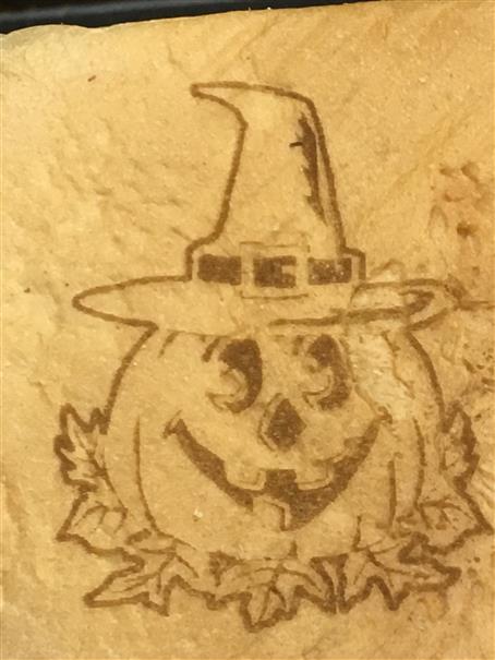
Now, I am going to cut using GCC LaserPro MG380 Hybrid machine. This machine we just installed on FabLab U Continental. From my point of view, it is a good machine. We have not had any problems yet. It allows to raster tubular objects and many more. As example I rastered a halloween pic in a slice of bread. Parametres: SPEDD 100% - POWER 80% - DPI 125 - PPI 400.
Let to use Corel Draw to cut or files.
1. Open Corel Draw and import the file.
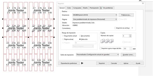
2. Select the vector or image that you want to cut or raster, Press "Ctrl + P". There will appear this window. Put a check into "Selección" option.
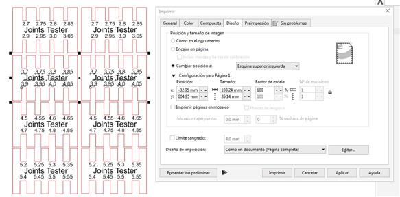
3. Click on "Diseño" tab and select "esquina superior izquierda" on "Cambiar posición a:"
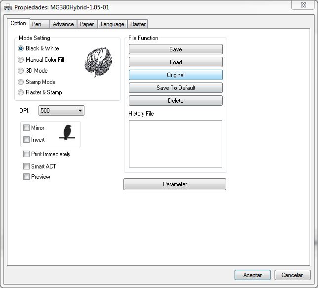
4. Back to "General tab" and click on "Preferencias..". On "Option tab", select "Black & White"
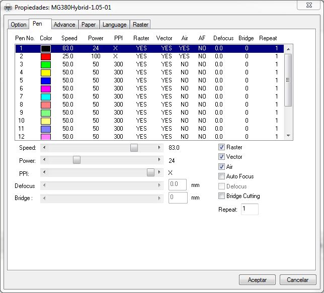
5. On "Pen tab" let's configure the following parameters. SPEED (0 - 100%), POWER (0 - 100%) and PPI (0 ,..., 1524,X). The machine recognizes the color of each vector, then use the values configured to each color to cut or raster.
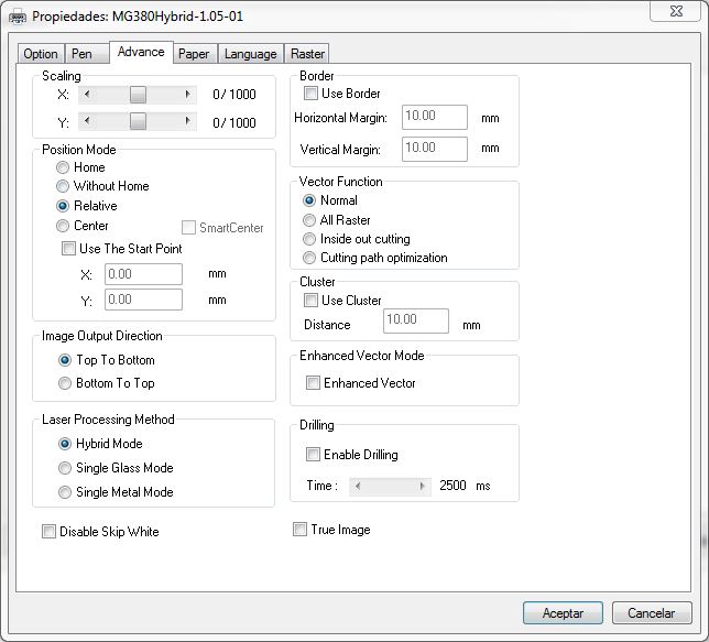
5. On "Advance tab" let's configure the following parameters as picture. The most important is the "Position Mode", check "Relative". "Image Output Direction" means raster direction from top to bottom or vice versa. "Laser Processing Method" when is selected "Hybrid mode" uses glass laser tube to cut and metal laser tube to raster; when is selected "Single Glass Mode" uses glass laser tube to cut and raster; and when is selected "Single Metal Mode" uses metal laser tube to cut and raster.
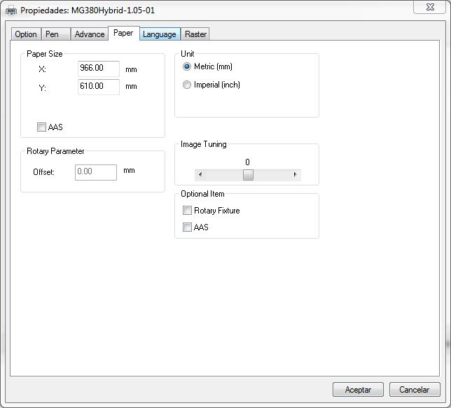
6. On "Paper tab" configure the paper size and the unit basically. If you want to raster in tubular objects check in "Optional Item / Rotary Fixture".
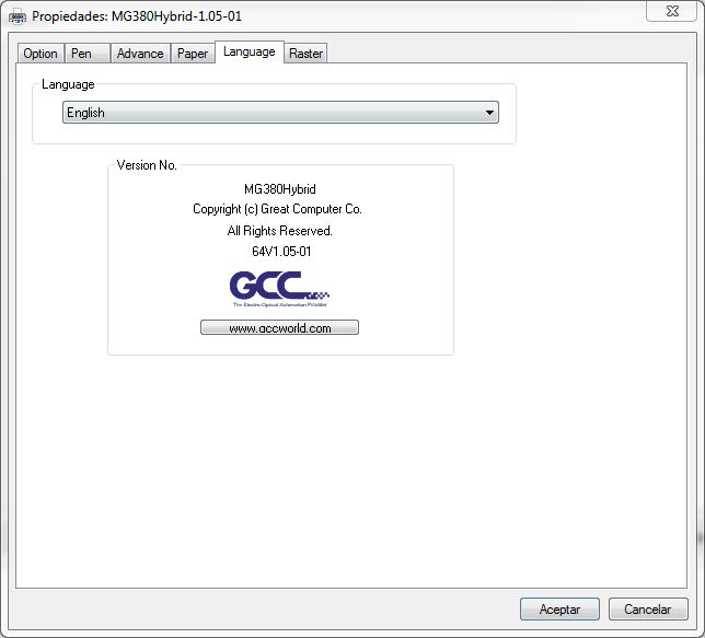
7. On "Language tab" configure language. In this case english.
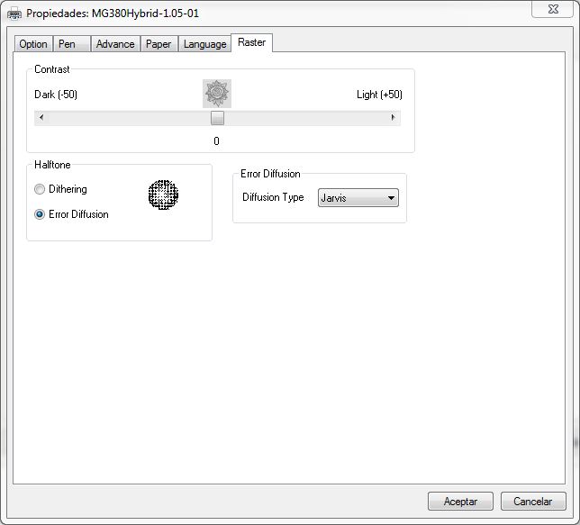
8. On "Raster tab" configure different parameters for advanced raster.
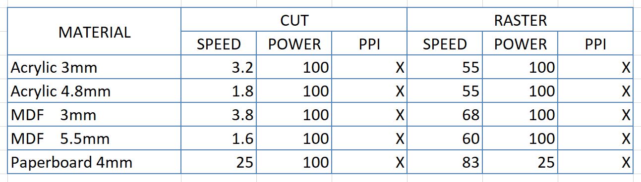
I did tests for five materials.
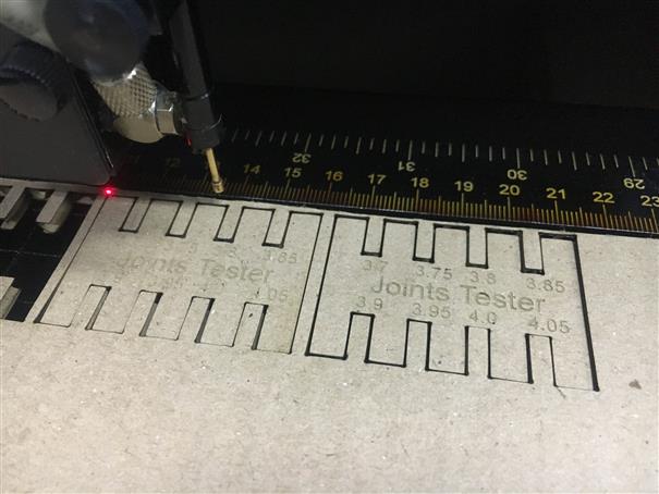
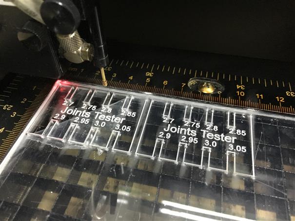
The results were:
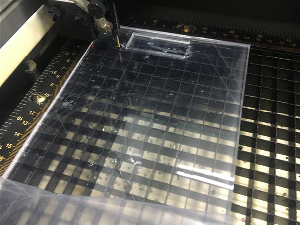
Acrylic 3mm ---> 2.7 pressfit width
Acrylic 4.8mm ---> 4.55 pressfit width
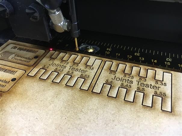
MDF 3mm ---> 2.7 pressfit width
MDF 5.5mm ---> 5.3 pressfit width
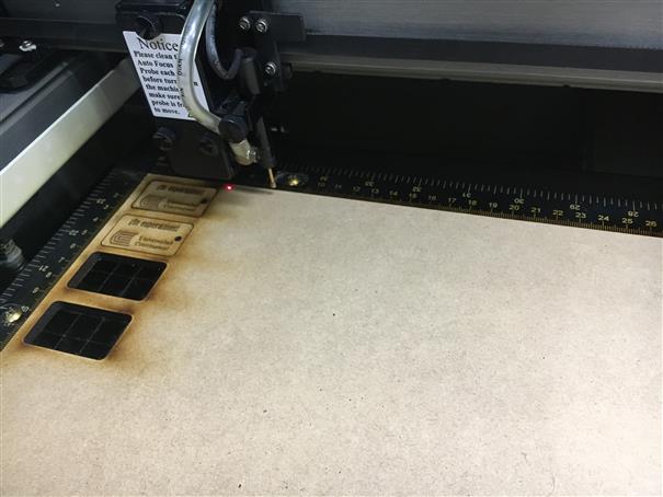
Paperboard 4mm ---> 3.7 pressfit widht
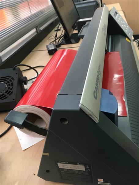
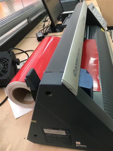
Vinyl Cutting
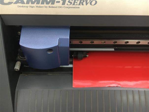
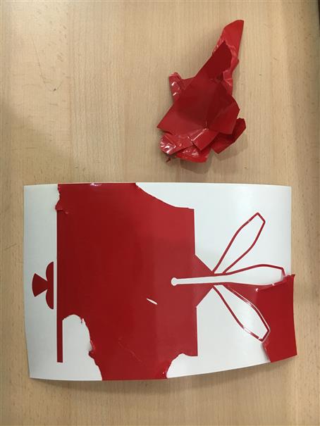
I did a sticker about my final project logo. I designed it on Rhino, then export a .dxf. Then, I opened it on Corel to export a .png format the only format to cut it on Roland vinyl cutter GX-24 that Fab moduls accept.
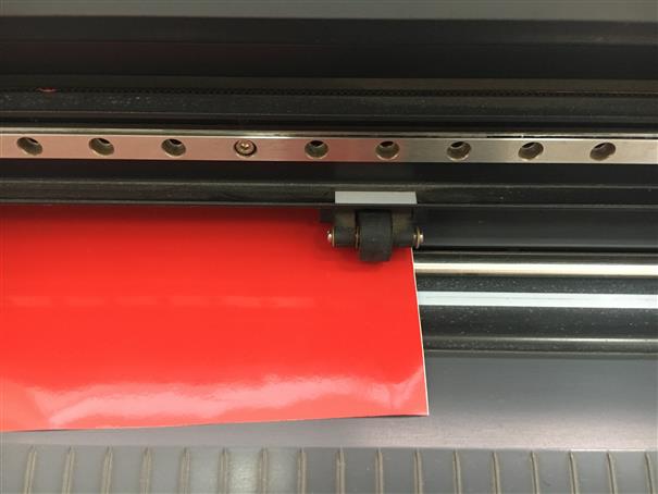
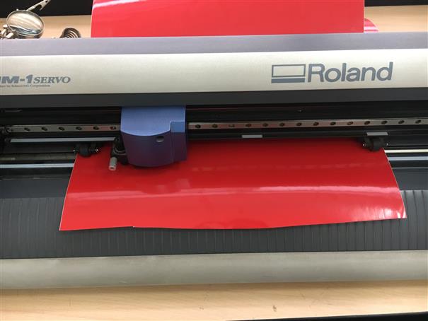
Loading Vinyl:
1.Lower the lever. 2.Insert the vinyl behind the machine. Preferably the vinyl should not be creased. 3.Align the vinyl. 4.Locate the rollers, one always goes in some white rectangular mark along with one end of the vinyl. 5.The other always goes on the far left inside the white rectangular bar about 10cm along with the other end of the vinyl. 6.Once the vinyl is centered, raise the lever and the rollers will exert pressure. 7.Now, turn on the cutter and choose if it is a roll or piece of vinyl.
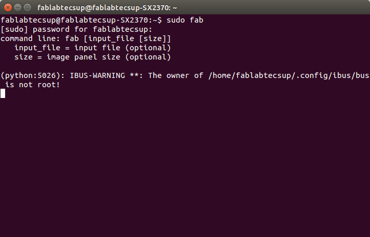
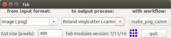
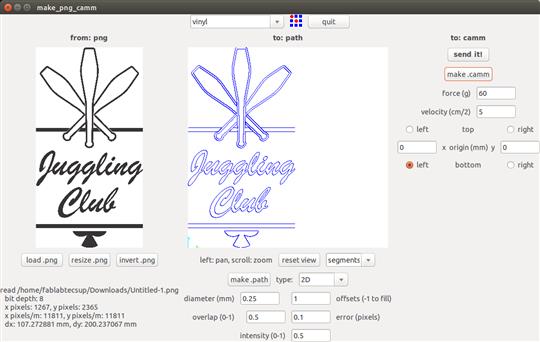
Cutting with Fab Modules:
1.Open Ubuntu terminal and write Sudo Fab. 2.Enter your password and press enter. 3.There will appear a window. 4."from input format:" gooing to choose "image(.png)" 5.Next, "to output process:" going to choose "Roland vinylcutter (.camm)". Click on "make_png_camm" 6.On this new window let to set parameters. At the top, choose "vinyl" 7.On your left, click on "load.png" and select your pic. 8.On the middle, check the value of "1" for offsets and "0.1" for error(pixels) the rest does not modify. 9.On your right, check the speed "60" and velocity "2" 10.Finally, click on "make.camm" and "send it!"
Carefully, remove the vinyl that does not need.
Files
Here, files: -Hand file (.dxf) -FabaClub logo -Wall files -Joints tester
Result
In conclusion, to get a better press-fit in each union reduce 0.3mm because it is the thickness of the laser.
Or can use this parametric design to have a good press-fit measurement.
We have a wall that could be cutted on different materials and can be builded in different sizes.