Previous assignment Home Next assignment


Week 3: Computer-Controlled Cutting

Laser Cutting

*make lasercutter test part(s), varying slot dimensions using parametric functions, testing your laser kerf & cutting settings (group project).

*cut something on the vinylcutter.

*design, make, and document a parametric press-fit construction kit, accounting for the lasercutter kerf, which can be assembled in multiple ways.

Learning outcomes:

*Demonstrate and describe parametric 2D modelling processes.

*Identify and explain processes involved in using the laser cutter.

*Develop, evaluate and construct the final prototype.

Have you:

*Explained how you parametrically designed your files.

*Shown how you made your press-fit kit.

*Included your design files and photos of your finished project.

Vinyl Cutting

There is no specific project that is focussed on this very useful tool. There are a range of ways you might utilise it throughout the programme, or your local instructor may set a specific project. You might make:

-stickers

-flexible circuit boards

-a textured surface/relief pattern

-screenprint resists/stencils

Ensure that you have used it in some way during this time and met the objectives below.

Learning outcomes:

*Identify and explain processes involved in using this machine.

*Design and create the final object.

Have you:

*Explained how you drew your files.

*Shown how you made your vinyl project

*Included your design files and photos of your finished project.


Laser cutting:

Group assignment:


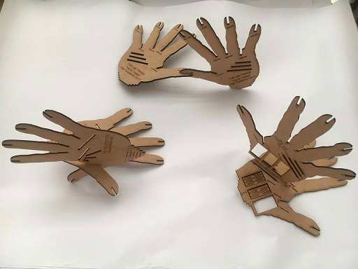
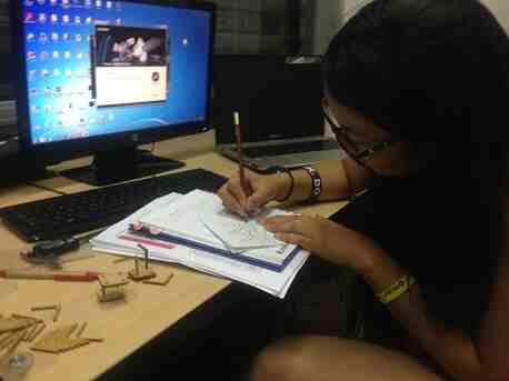
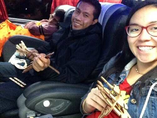
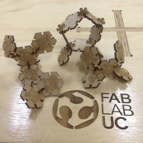
In order to carry out this assignment, we met after class and began to propose ideas for the design of the joints tester.


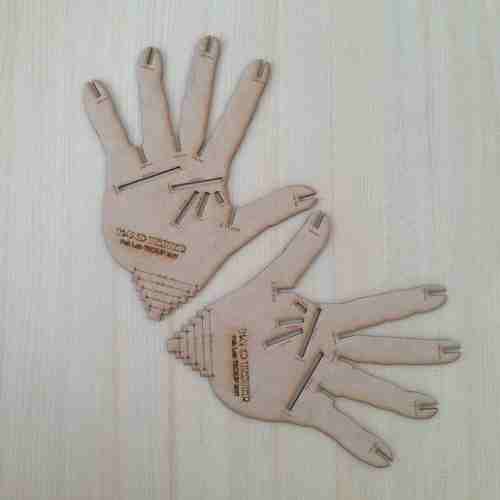
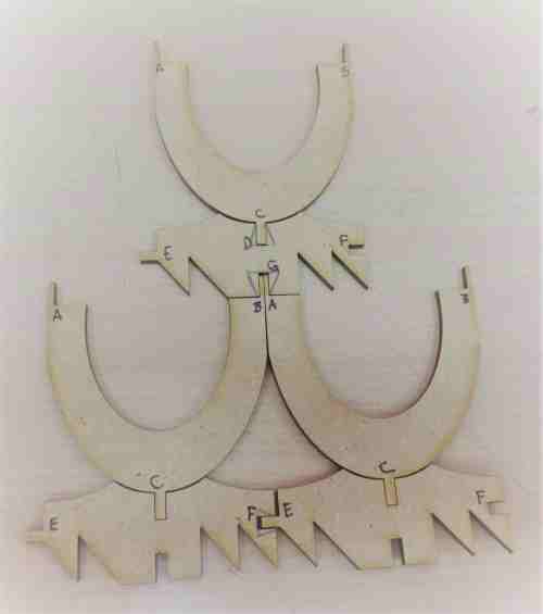
There is my "Hand Tester", we call it so for design purposes.

As you can see, we have different kind of joints there: on the fingers, between the fingers and on the palm.

This is a creative way to try if the joint will be the best choice for making the idea you have in mind.

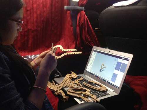
In my case, I tried the following measures: 2.8, 2.85, 2.90, 2.95, 3.00, 3.05, 3.10, 3.15, 3.20. All in millimeters. At the beginning, I had some troubles understanding why should we play with different measures but I got it finally when I started designing.

The best joint for me was 3.00 with 2.95, I worked with MDF of 3.00 mm thick.

If you try 3.00 with 3.00, the fit will be loose.


Individual assignment:

To do: to cut something on the vinyl cutter

To design, make, and document a parametric press-fit construction kit, accounting for the lasercutter kerf, which can be assembled in multiple ways


Vinyl cutting:

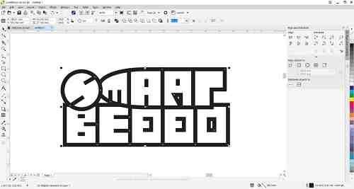
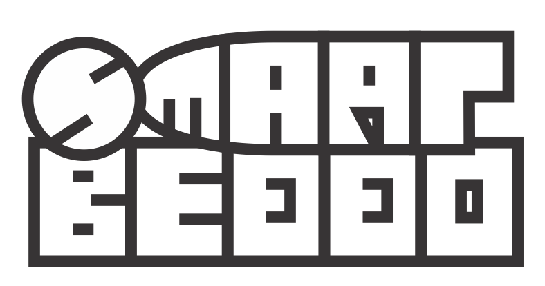
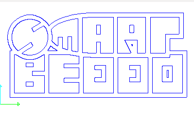
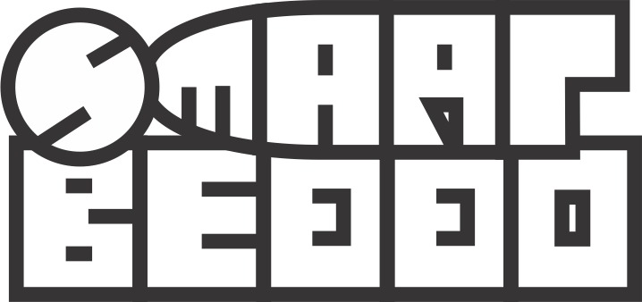
I opened CorelDrawX7 and drew my final project logo, with it I will make a sticker for my lap top.

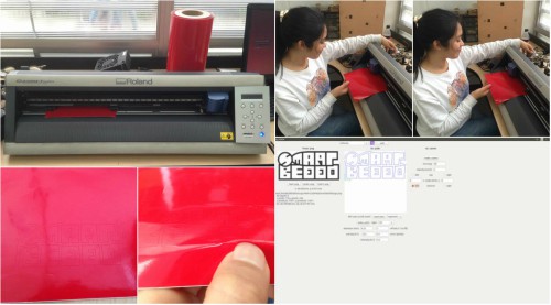
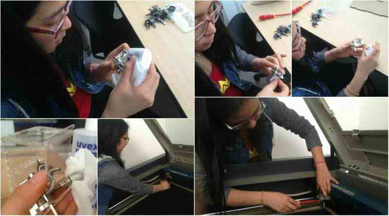
For this challenge I use the Roland CAMM-1Servo machine.

Let's see how can we do it


First we have to export the design as .png format

The design have 4 px of contour width and 6cm*3cm of size.

Here you can download the .png format

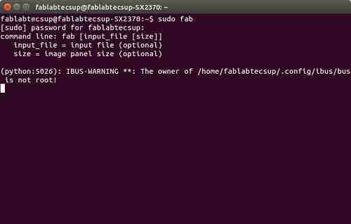
Then I had to open in Ubuntu, the software that we use for work with the Roland Viinylcutter machine


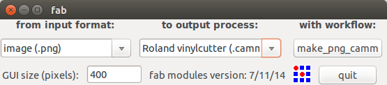
As you can see at the picture, those are the steps:

from input format: image(.png)

to output process: Roland vinylcutter (.camm)

with workflow: make_png_camm (Clicked it)


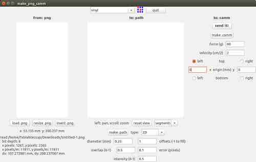
Now we have the main screen, as you can see in this part, I had to choose vinyl as material and all the options change by default.

I had to change the offsets option, wrote 1, it means that only one stroke will be made with the blade.

Change the error option, wrote 0.1, to get a better result, detail and quality. And clicked on "make .path"


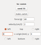
Finally, in this part before I clicked on "make.camm", I had to change the force,wrote 60, and velocity, wrote 2.

I selected "left" as origin where it will start to cut

Left "0" in "x" and "0" in "y"

I clicked on "make.camm" and after 5 min. I got my sticker.


As you can see there is a mistake, I can't got my sticker! :( so, I will try again!

First, I will analize why it happens.


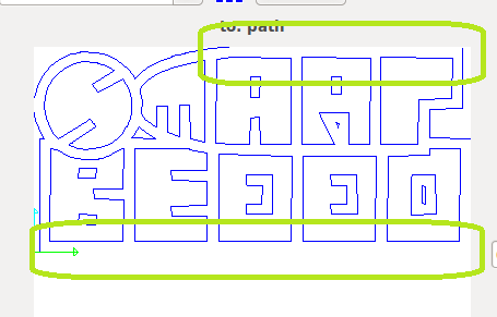
My design is not correct for this format, I had to made a contour and improve it to get a best result. Also I will change the force and velocity before "make.camm"


Looks different with contour.
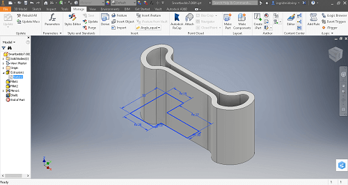
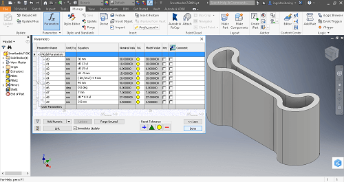
Parameters

Force (g): 100

Velocity (cm/Z): 5

Left

Clicked on "make.camm"

Now I will sen it !

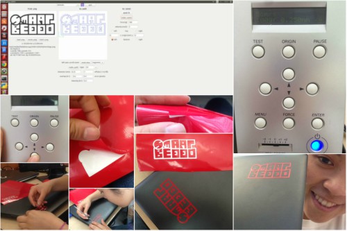
That is how I got my Smartbeddo sticker


Press-fit construction kit:

Sketch:

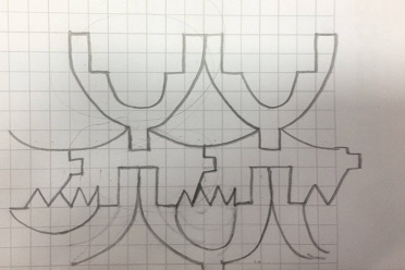
I started drawing some ideas

After hours, I decided to make a press fit construction kit's bag
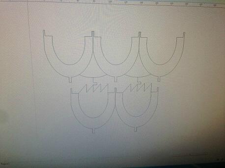
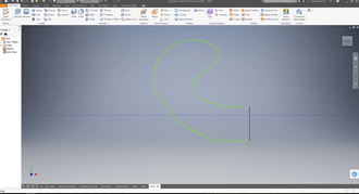

Design:

I started designing using Corel Draw. That's how I got the pieces for my bag.
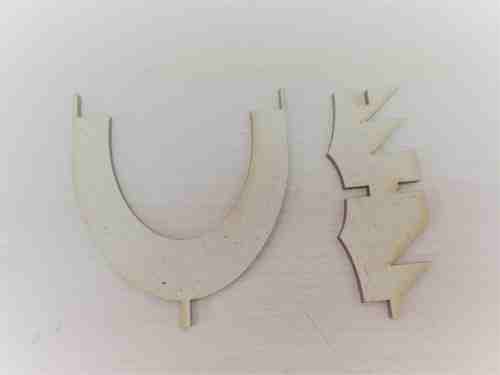
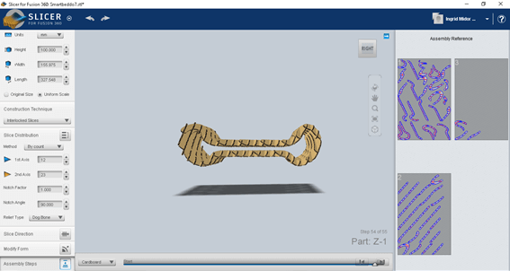
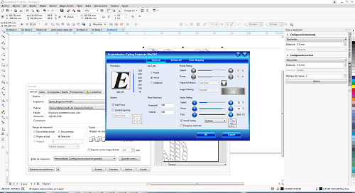
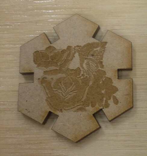
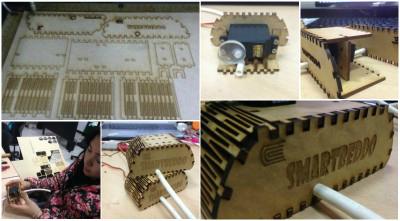

Cutting:

I worked in MDF of 3mm thick. As you can see on the GIF, I planned to use these two pieces for the "weave" of the bag, with a tribal design. Then I cut them with "Epilog Legend 36 Ext" using the following parameters: Speed: 30%, Power: 80% and Frequency: 100%

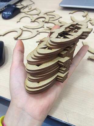
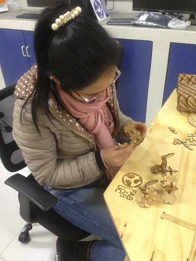
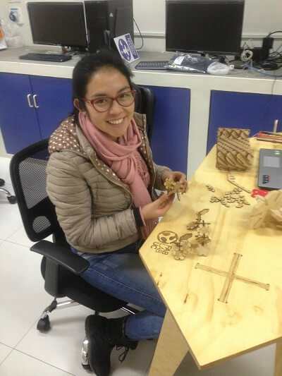
I got the pieces and just cut some to try. I luckily did that. When I started to build my bag, I discovered that I did not have so much success. I learned a lot, but now I will have to re-test the changes for the observations I made.


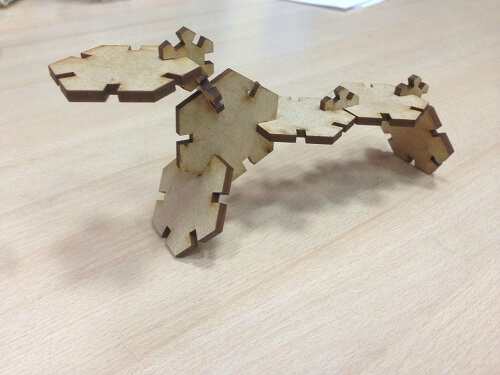
What did not work was:

When you join A and B to fit into G, it becomes loose and does not support the pieces.

When F and E join, it is loose.

The design will not allow you to fold it to a bag unless you opt for a square style. That's an idea that does not excite me so much.


What did work was:

I like the tribal design it has.

C fits well into D.

To improve:

I will make another design for the joints (I painted them with a pencil)


Second idea:

I decided to use the waste to create a pot. In order to achieve this purpose I opened "Inventor" and started designing.


Individual challenge:

I will work with MDF of 3 mm of thickness.

These are the parameters:

autofocus: activate

power (%): 30

speed (%): 90

rate (pps): 5000

To get an optim result

Parametric press fit kit construction

DESIGN: Here I will explain you how I made a parametric 2D modelling.

Thinking about my final project, I decided to make a Parametric mattress support

I opened Inventor and started drawing, after reading this thesis, and watch this video, to understand better what about it is "parametric"

A parametric design means that you can modify the dimensions but the design of your project wont be altered. To achieve this, I used Inventor software and created a parametric design using the restrictions and the software tools:

From this sketch I created the solid.

In order to generate the parametric function, the dimensions of the project should be functions based on a main function.

MAKE: Then I exported it into "Slicer" software, after having saved it in .stl format.

It's easy, in this case I used these parameters:

Units:mm

height="100"

width: by default

leigth: by default

Contruction technique: Interlocked Slices

1st axis: 12

2nd axis: 23

factor:1

angle:90

Fillet type: dog bone

Slice direction: right

Then I exported the planes to open in CorelDraw X7 to work with the elaser cutter:

This one takes lot of time, I started when I was traveling to Huancayo with Jhon and finished when I came back to Lima.

Press fit kit construction

DESIGN: In this case I also used Inventor software to make a simple perfil without a specific dimension, and I get this pot:

MAKE: Some pictures and videos, below here:

Pot by iMidoriNY on Sketchfab

Then I exported to Slicer:

And exported the planes as pdf, to open in CorelDraw X7(to verify dimentions) to work with the laser cutter:

Modular Press fit kit construction

DESIGN: In this case I also used Inventor and drew this module, then I exported as drawing and open in Corel Draw X7 to add the raster design that I made of Huancayo textil, in order to show a little bit of my culture, I'm proud of being Peruvian, I'm proud to be from Huancayo.

MAKE: You can build multiple ways using these modules:

Result:

As you can see I made differents designs and learn that the main diference between a press fit design and parametric press fit design is that in a parametric design you can change dimension and this wont affect the design , it means it is scalable too, in a simple design will be a mess. And a modular design is when yoy have lot of the same piece and you can join it in multiple ways to make whatever you want.


As the time goes by I learned to use better Adobe Ilustator and Corel Draw to make 2d designs and use the correct thickness to make a press fit kit. For the second prototype for my final project I designed this case for the servo motors.


Cleaning:

Through this experience I also learned how to remove the lens from the machine and perform the proper cleaning. For the lens cleaning I used about two drops of the cleaning liquid that the same provider gives. Then with Uvex I cleaned the rules, from the work area.

It was a pleasure to learn how to take care of this beautiful machine.


Self Evaluation:

Laser Cutting

At this point, I can say that I know how to use Epilog legend machine and work with differents material as MDF, Cardboard/paperboard, Vinyl and Acrylic of differents thickness since 2 mm to 8 mm.

Vinyl Cutting

I learned how to make stickers with the Vinyl cutter but I will try in the future to make a flexible board and others.


You can find all the files here (Also extra designs)


Files (On Drive)

Vinyl cutter

Laser cutter


Previous assignment Home Next assignment