

-Understand the controller's datasheet
-To program the board to do something
-Learn how to program the board
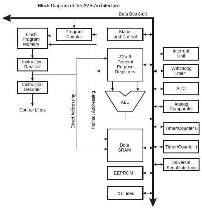
First I got a copy of the Atmel Attiny 44a datasheet's.
I think it's amazing for this microcontroller to have all those features.
I found a lot of usefull information but I also found lot of details i did not understand.
Since this assignment is about programming a button to control a LED, the information located on the 10th section was really useful. It describes how to configure, supervise and control inputs and outputs
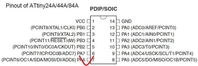
When designing the circuit, I noticed how each pin of the chip was labeled with some shortcuts
For example: the 13th pin is labeled as PAO (ADC0 / AREF / PCINT0).
From the datasheet I read some alternative functions of the ports.
        ADCO:  Identifying inputs and outputs
        Port A, Bit 0 – ADC0/AREF/PCINT0 (Atmel 60th page)
        • ADC0: Analog to Digital Converter, Channel  0.
        • AREF: External Analog Reference for ADC.  Pullup and output driver are disabled
        on PA0 when the pin is used as an external reference  or Internal Voltage
        Reference with external capacitor at the AREF pin by setting (one)  the bit
        REFS0 in the ADC Multiplexer Selection Register (ADMUX).
        • PCINT0: Pin Change Interrupt source 0. The  PA0 pin can serve as an
        external interrupt source for pin change  interrupt 0.
Here is the microcontroller's datasheet
The 6 pins of ISP communication were identified
Procedure for using the library “fab.lbr”
1. I selected Fab Academy (http://fabacademy.org/)
2. selected CLASS ARCHIVE -> 2017->SCHEDULE->ELECTRONICS_DESIGN
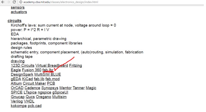
2. Download and save the library to a folder.
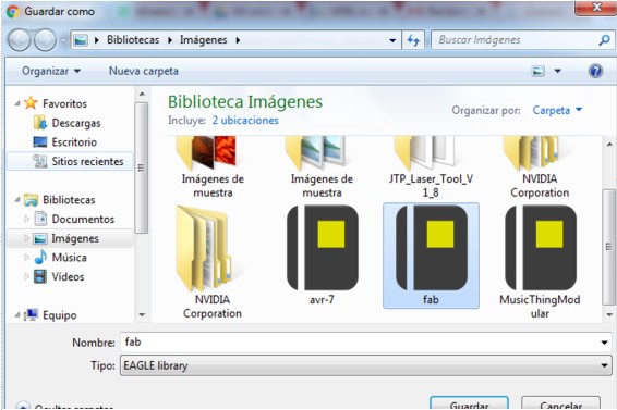
3 Activate the Eagle program and then add the library.
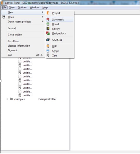
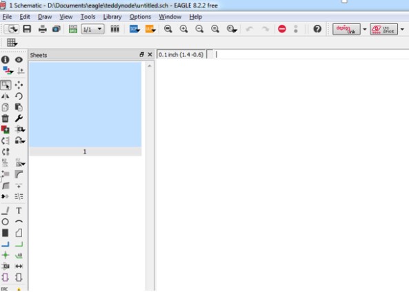
4. I opened a new schematic.
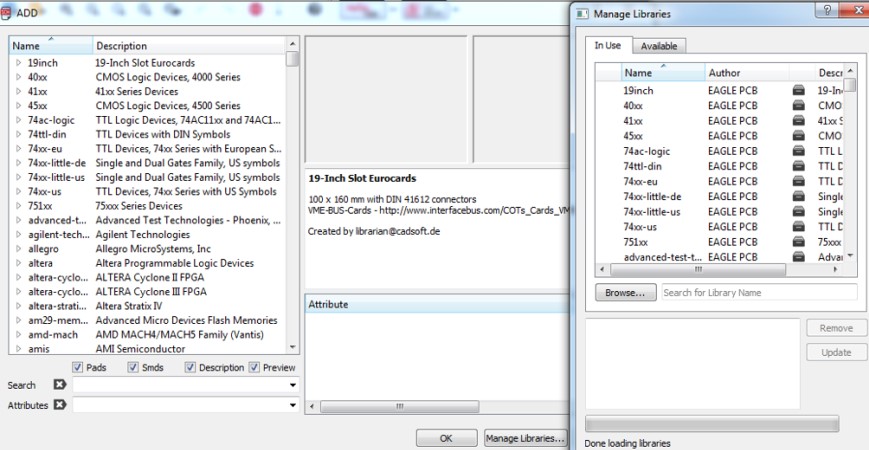
5. Then select the ADD option and open a window where we can upload the FAB.lbr library in Manage Libraries.
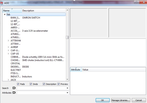
6. Finally I was able to use the components of the Fab Academy Library.
1. I opened EAGLE software.
2. I created a new schematic
3. I searched the components in the library "Fab"
The following components:
- ATTINY44-SSU (ATTINY44)
-AVRISPSMD (AVRISP)
-RESONATOR
-FTDI-SMD-HEADER
-LED
-RES-US1206FAB (RES-US)
-CAP-UNPOLARIZEDFAB (CAP-UNPOLARIZED)
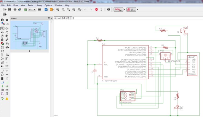
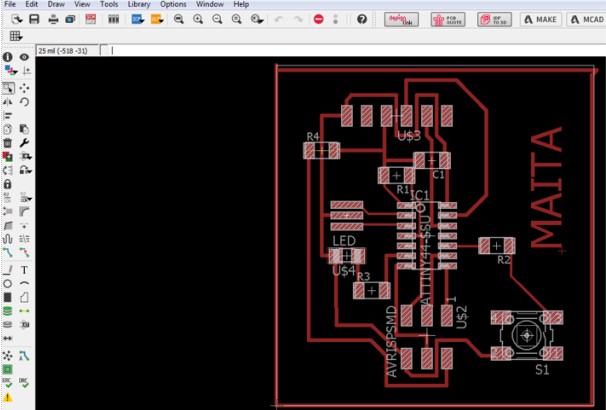
4. Make the connection of the pins in our schematic sheet.
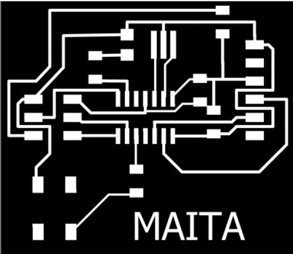
5. Then generate a board where we will accommodate the components for our plate design.
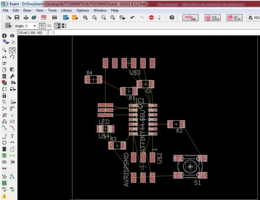
6. Then route all the tracks so that everything is on the layer "top".
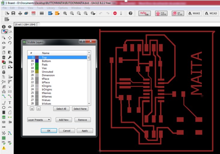
7. Then only activate the "top" layer in visible.
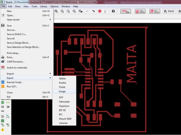
8. Then export my design to an image.
9. Then place the following parameters and give an address and name to our image.
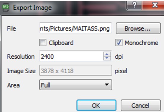
10. And I have ready my new electronic design ready to be mechanized
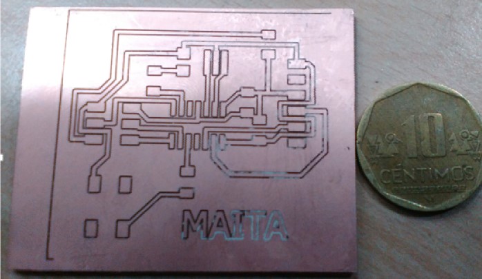
Machining
Make my own design of my electronic card Then perform milling with a 1/64 "diameter cutter on the electronics board in the Roland milling machine" Model MDX20
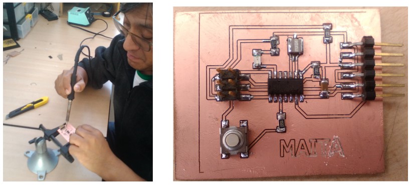
Welding
Solder the components on the electronic board.
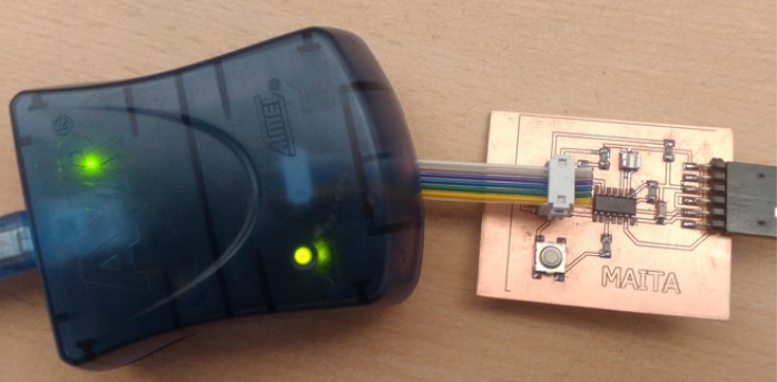
VERIFICATION AND PROGRAMMING
Make the ABR connection to check if there is a short on my electronic card and then I made the programming.
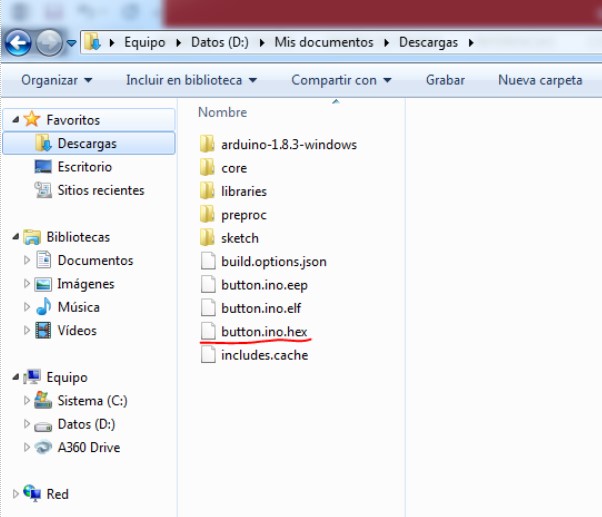
Procedure for obtaining the HEX file from Arduino IDE
Obtaining the file HEX from ARDUINO IDE.
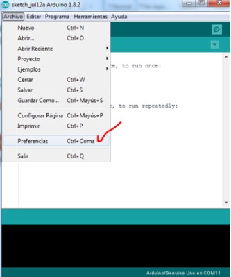
1. I executed arduino software.

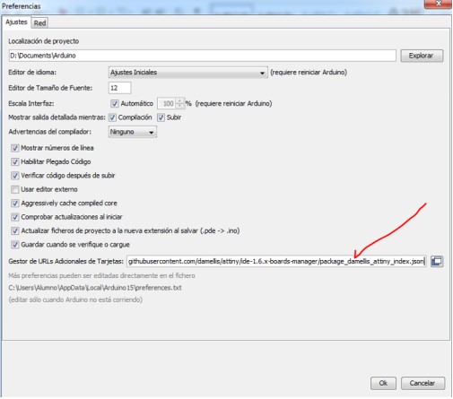
2. I pressed Ctrl+Coma for open “Preferences”
3. Click on the address
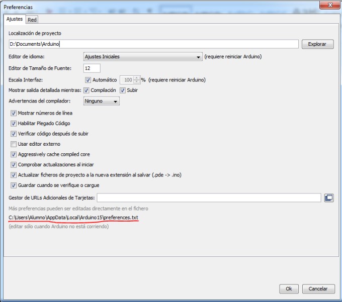
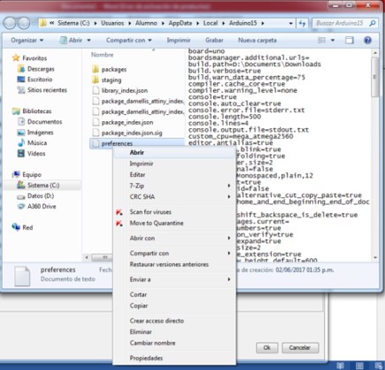
4. I opened the preferences file.
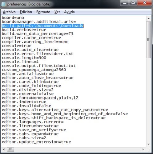
5. Edit in the line "build.path", giving an address in my case I direct it to the download capeta
6. Return to the preference option and place the following link “https://raw.githubusercontent.com/damellis/attiny/ide-1.6.x-boards manager/package_damellis_attiny_index.json” inside of “Gestor De Urls Adicionales De Tarjetas”
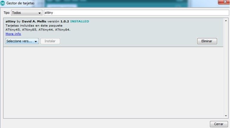
 7. Then open the Card Manager window and look for the word "ATTINY" and download the cardboards.
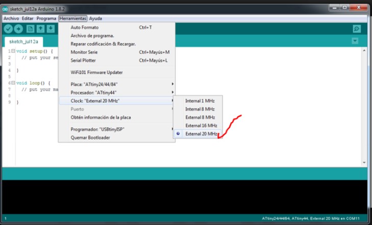
 8. Now I have the plates of Attiny in the option of plates, and we can program the plate Button, in my case my processor is ATtiny 44, with a clock of 20MHz
 9. Perform the programming and compile in the Arduino IDE program (We do not upload the programming)
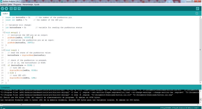 10. Then I went to the download folder where I chose to generate my HEX file.