


- Manufacture a calliper for the material you will use.
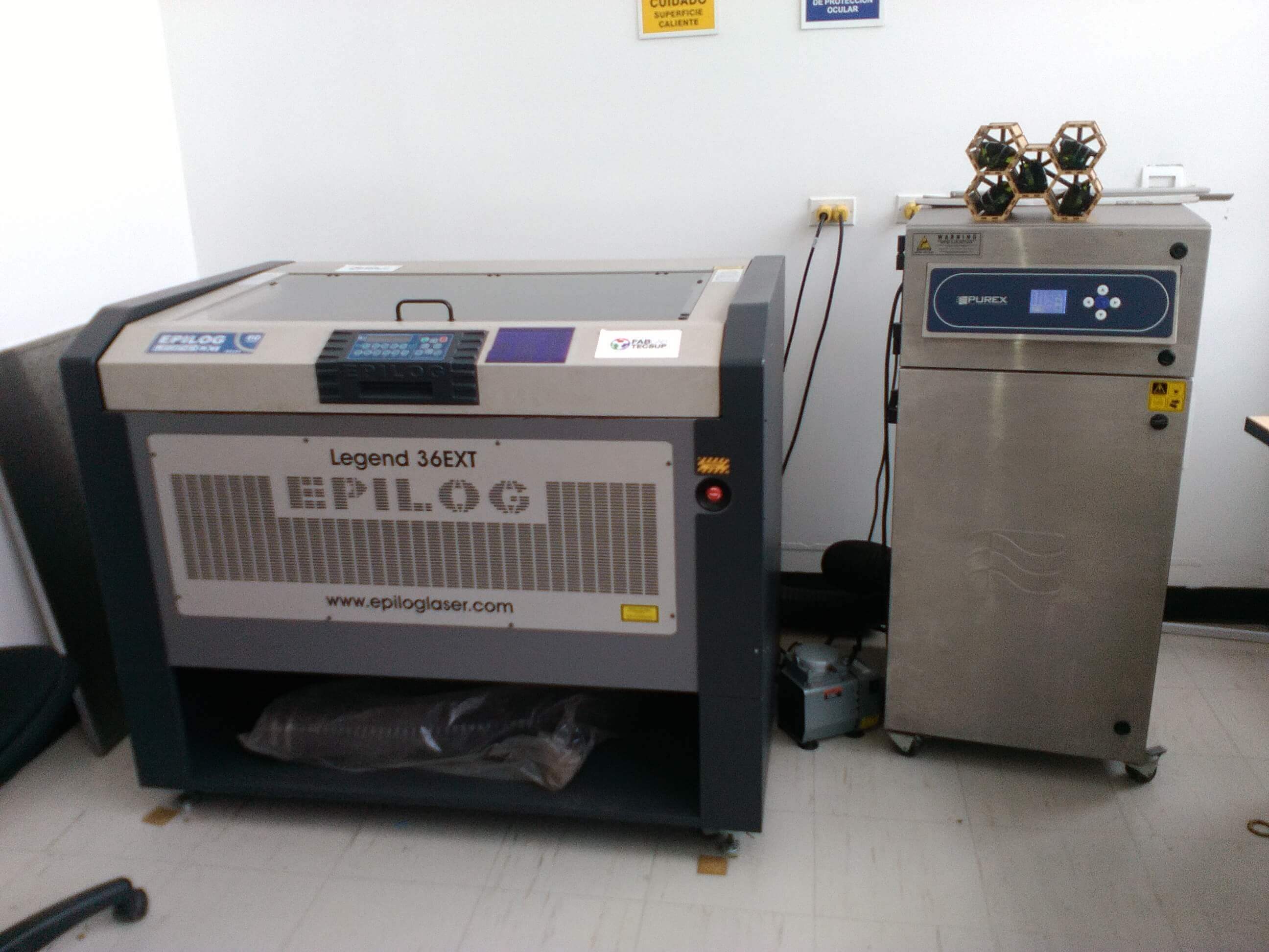
- Demonstrate and describe the procedures used in laser cut.
We decided to do the calliper hand as a groupal work. You can see the details on the board
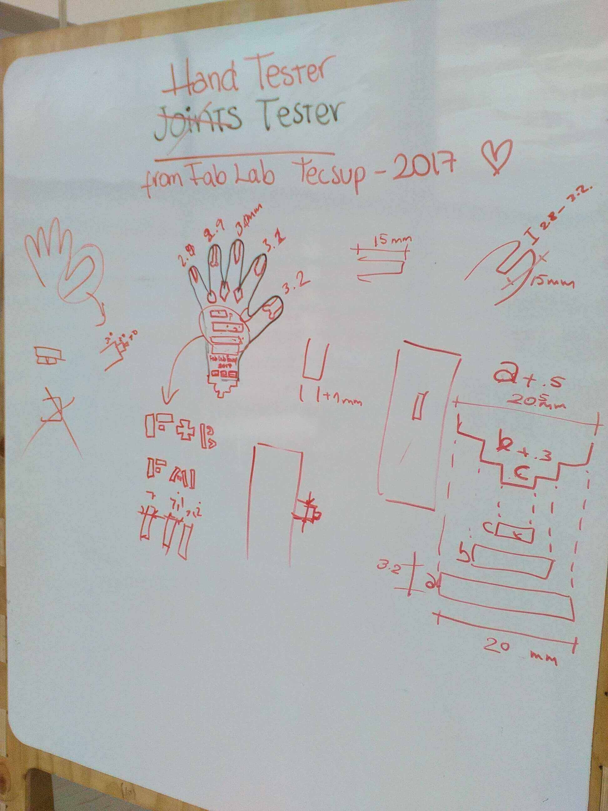
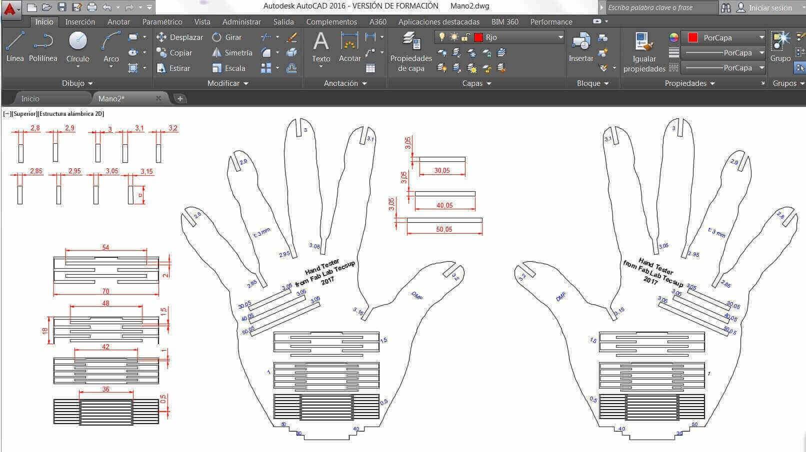
To do this design every team member used the software they know the most.
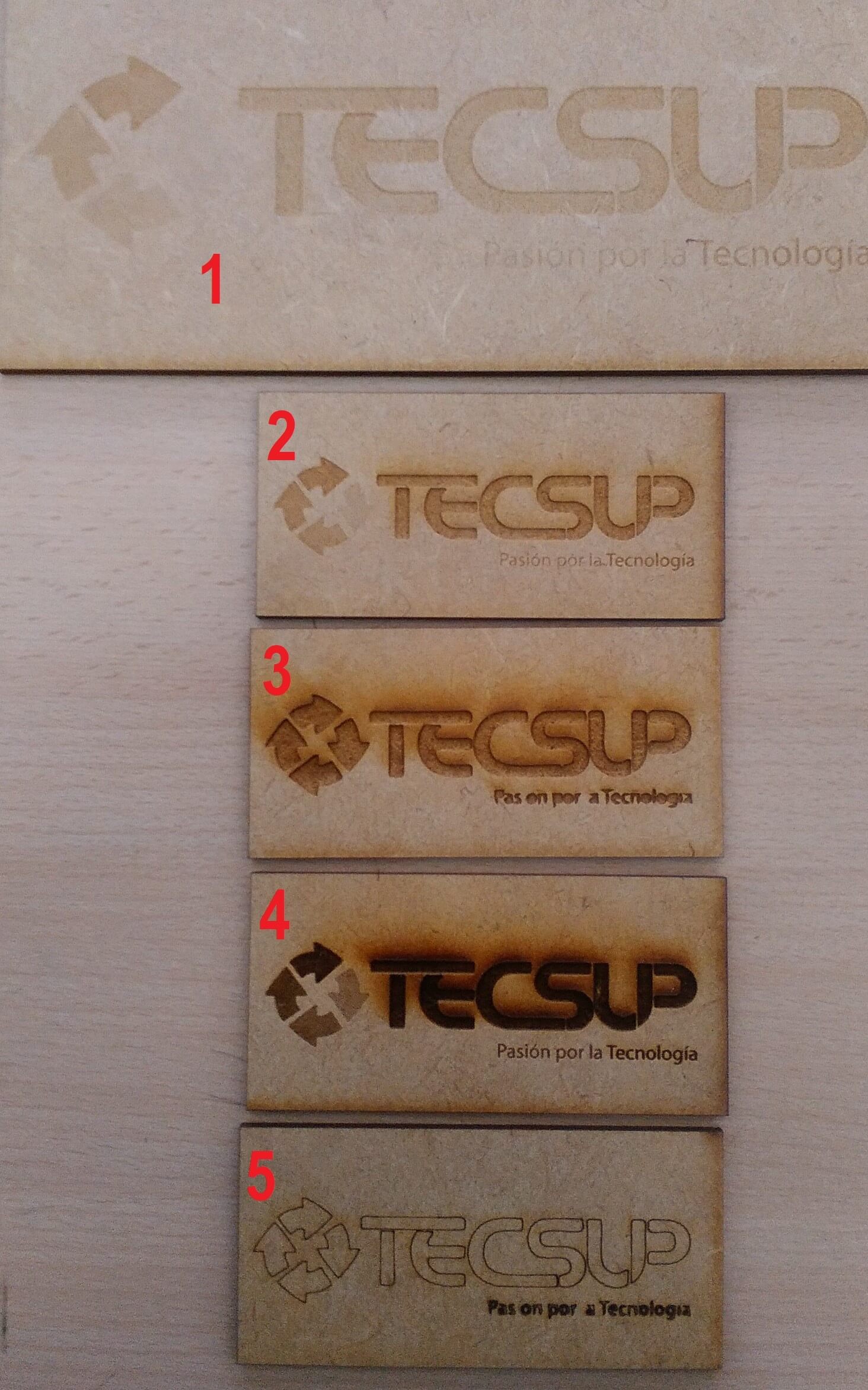
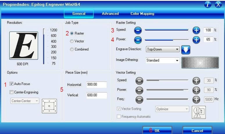
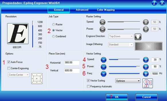
We did the raster Test using the following configurations:
1- Speed 100% power 75%
2- Speed 70% power 100%
3- Speed 50% power 100%
4- Speed 20% power 100%
5- Speed 100% power 75%
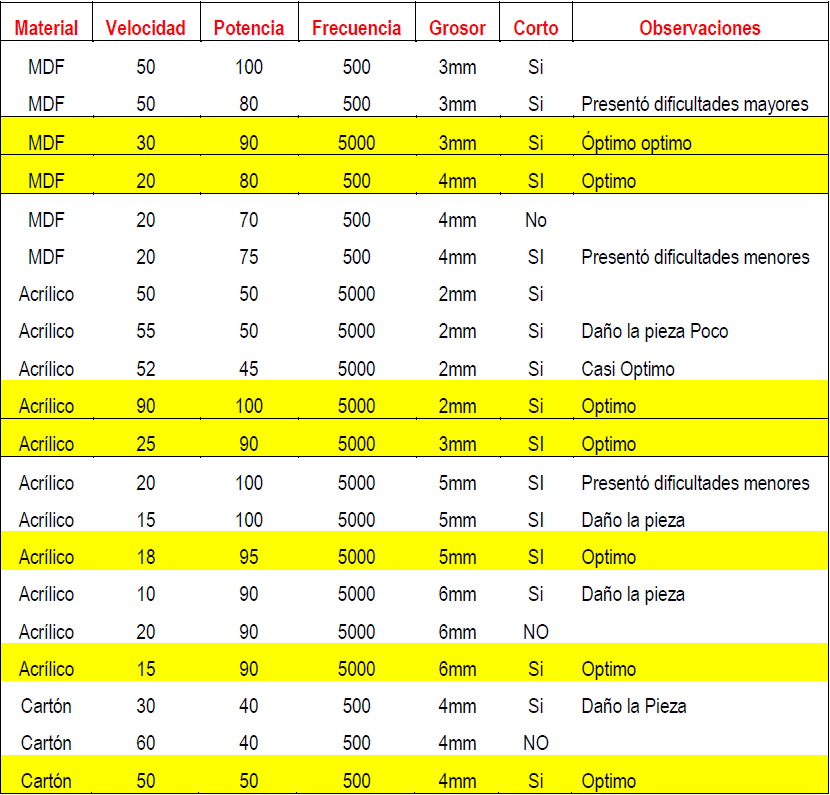
Then we did the cutting test using Fablab Materials
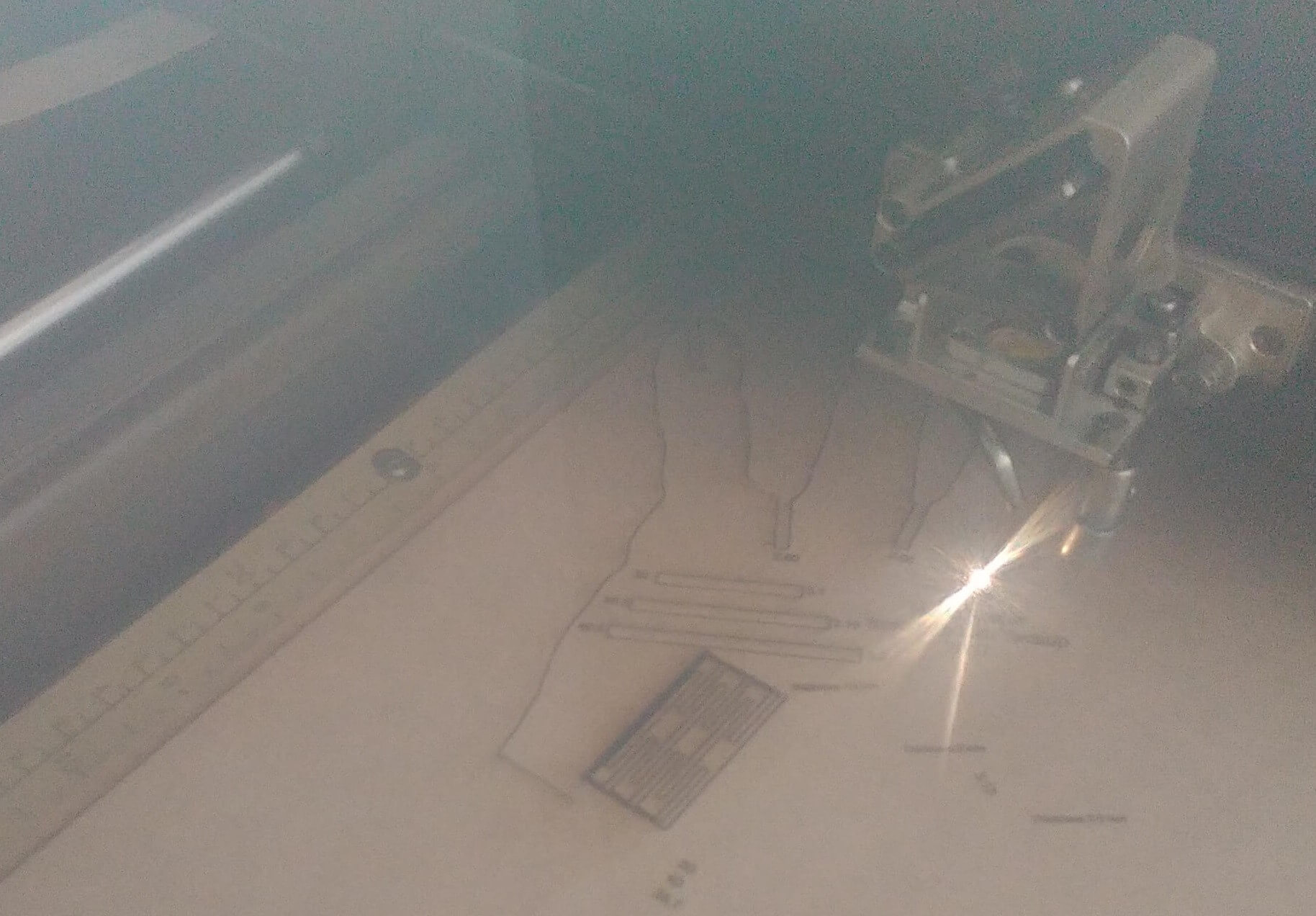
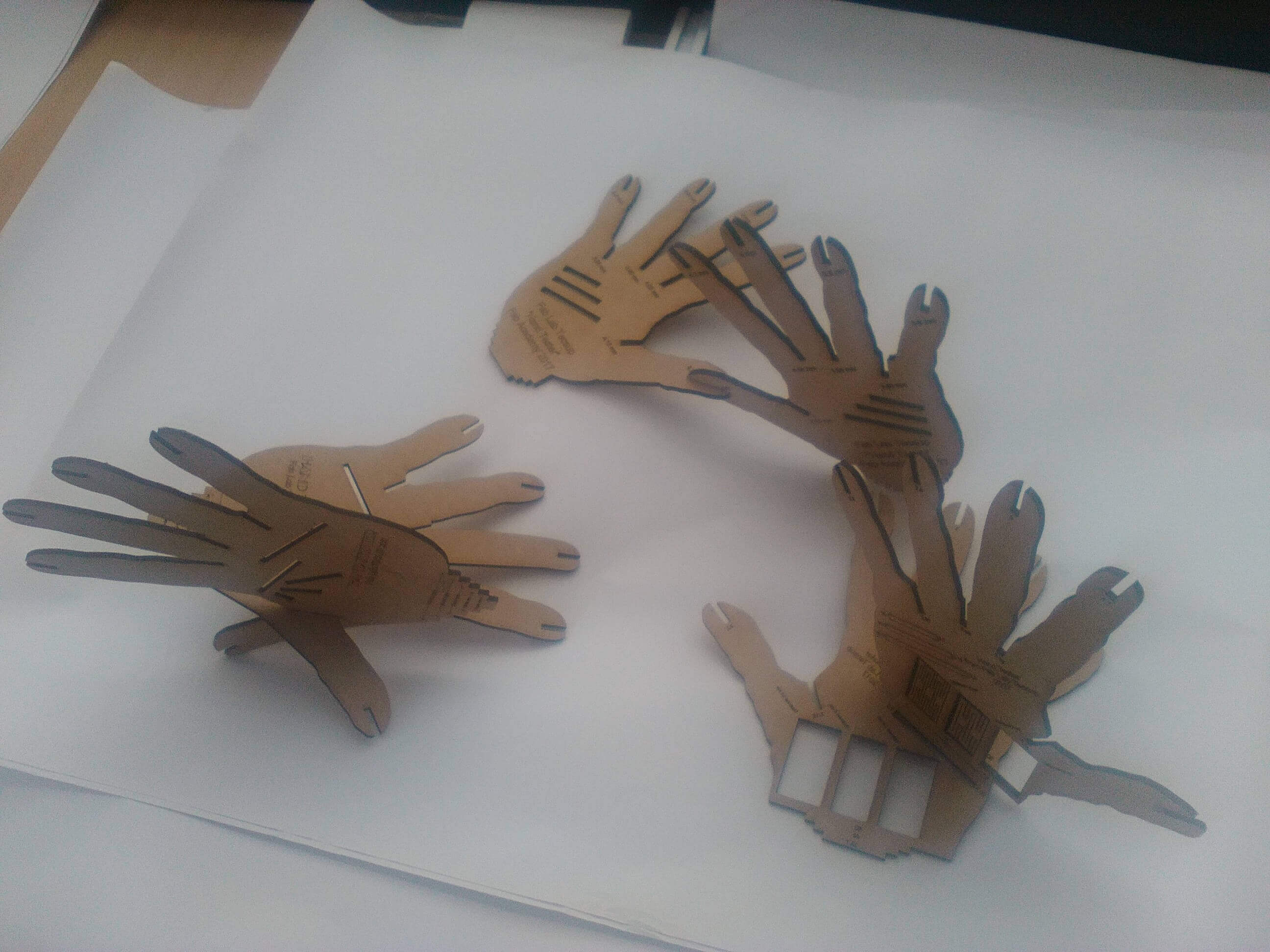
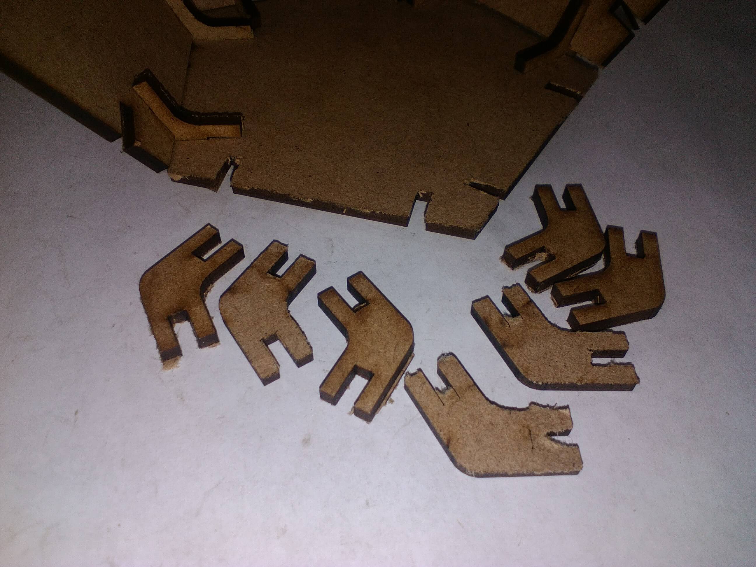
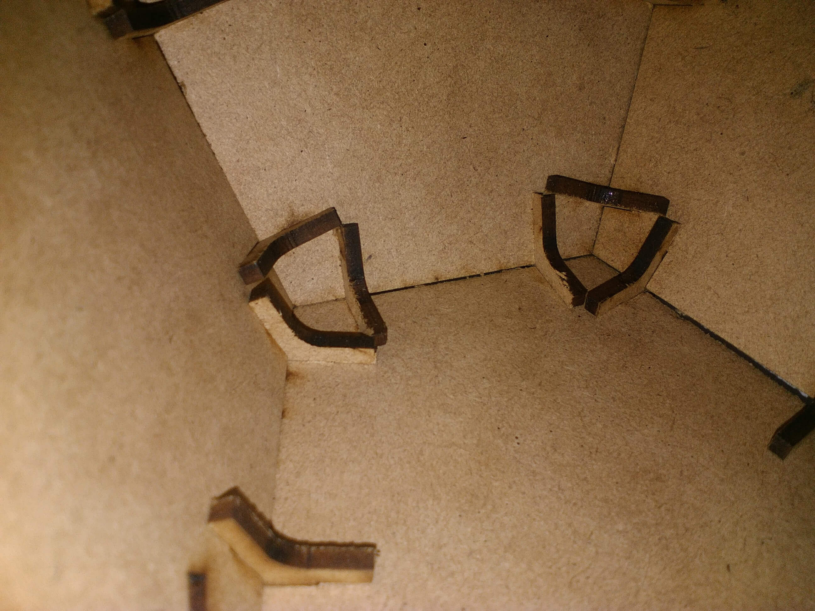
After the raster test on the hand, we did the cut. Once we got the pieces, we tested the hands on each slot
Results:
- Slot 3 with 3 mm fits a little loosey.
- Slot 2.95 with 3 mm also fits a little bit loosey
- Slot 2.95 with 2.95 fits a little loosey
- Slot 2.90 with 2.90 fits realy good.
- Slot 2.95 with 3.5 fits a little bit loosey
- Demonstrate and describe the parametric modeling process
- Identify and explain the lasercut process
- Develop, evaluate and fabricate a final prototype
- Design, fabricate and document the vinyl cutter process
The parametric drawing is a technology used to design using constrains. Those are restrictions aplied to 2D geometry. There are 2 types of constrains: Geometric constrains control the relationships between components, and the dimention constrain uses values like distance, length and angle of the objects.
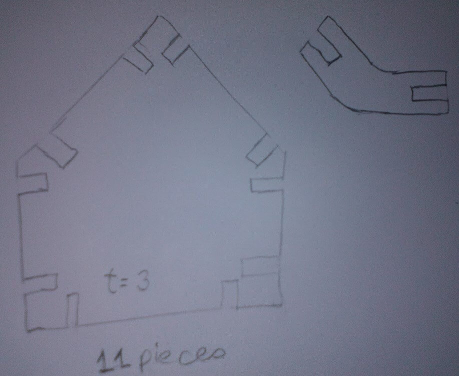
I found a joint on internet
I made the sketh by hand, trying to keep the ratios (A4 sheet, 3H pencil)
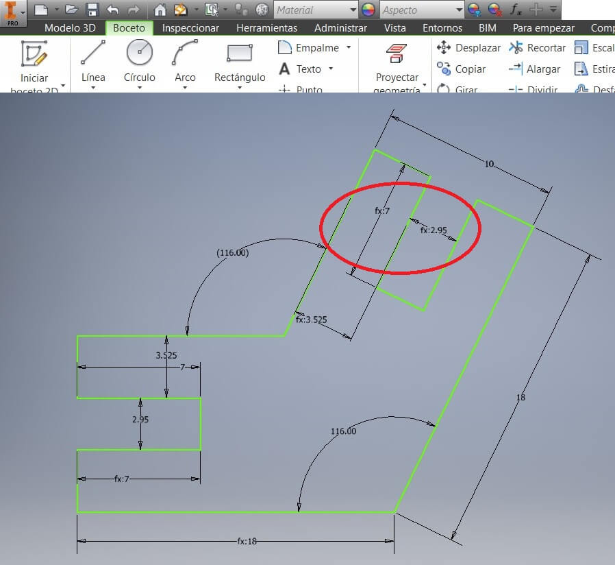
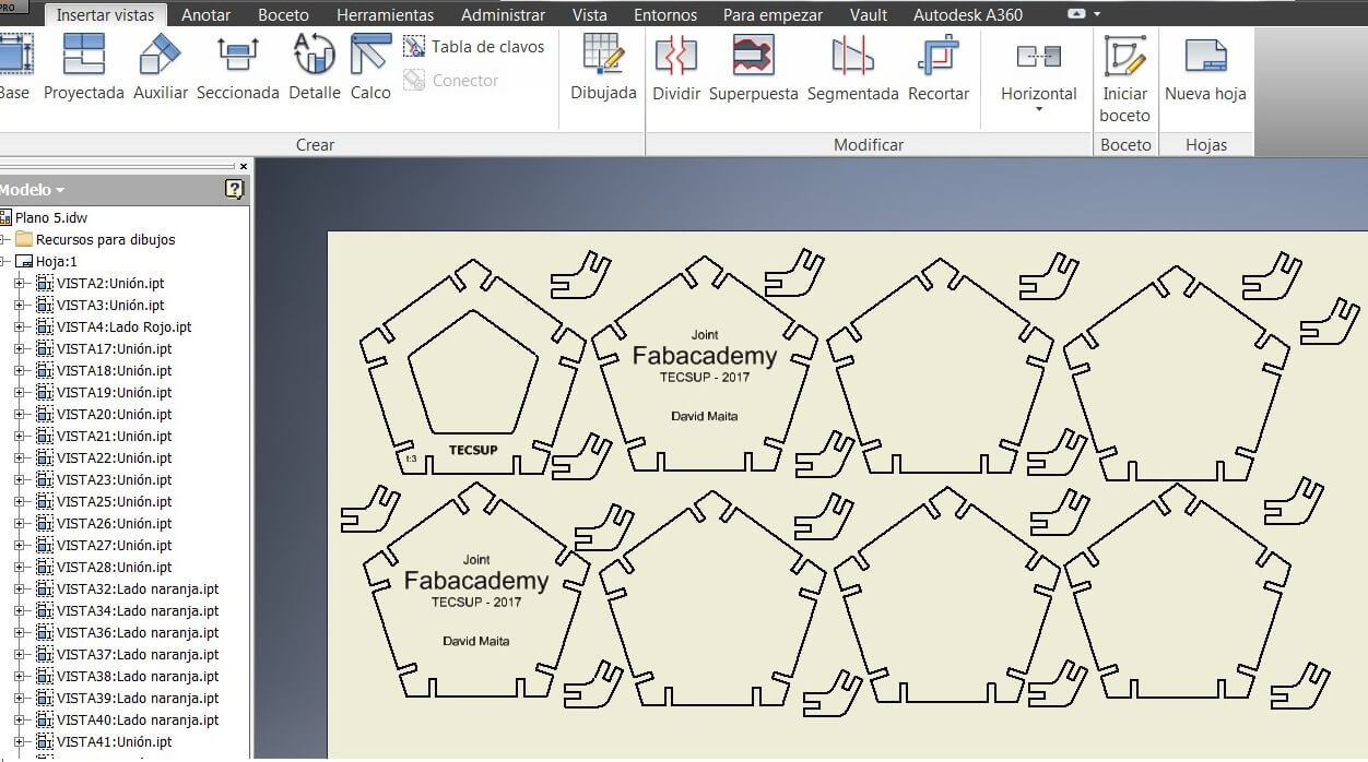
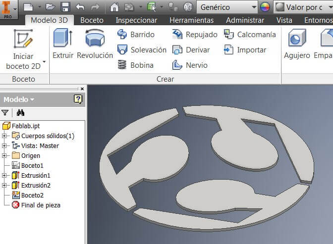
I drew the sketch using Inventor this time, and following the 2nd week procedure to model the following objects
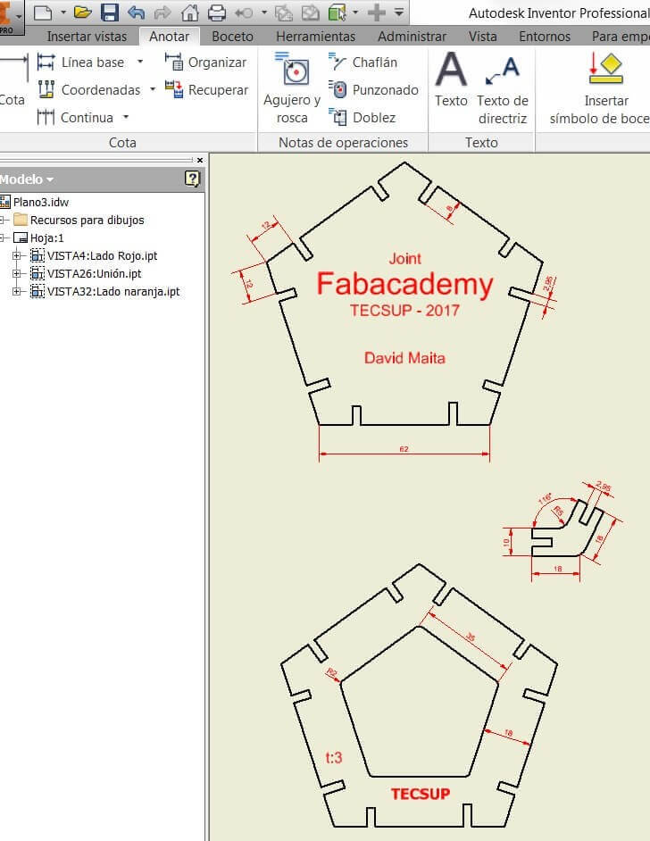
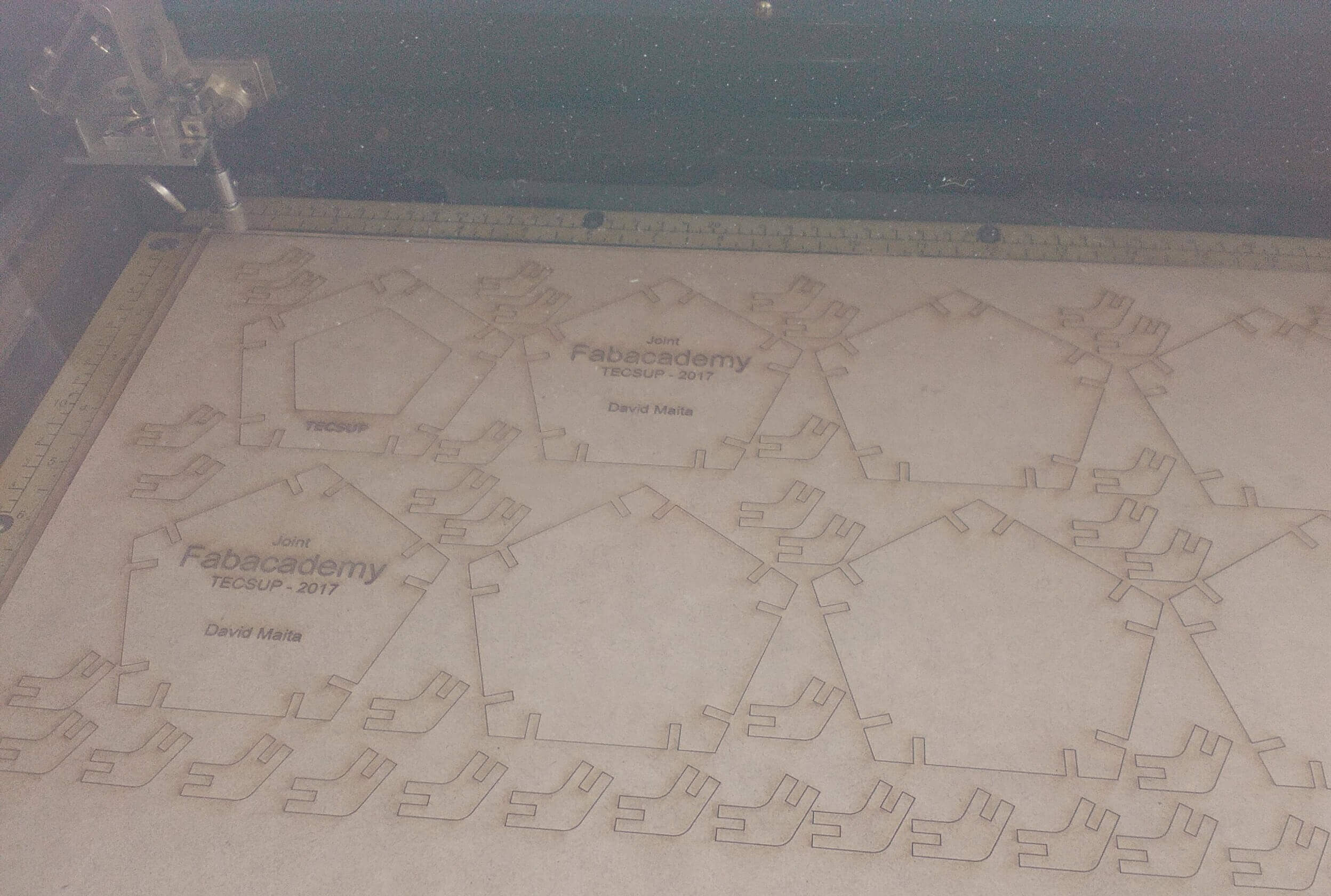
I generated the fabrication plans (.idw) on other sheet and optimized the material by placing the pieces close to each other on the 900 x 600 mm space
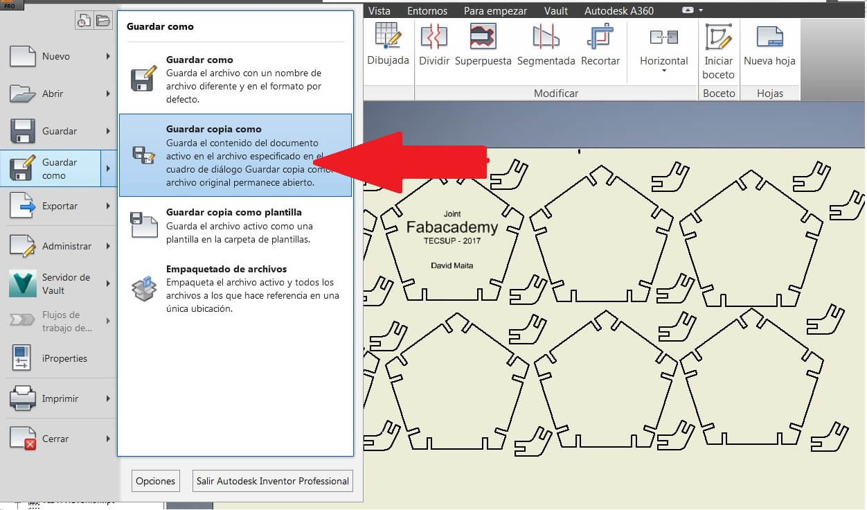
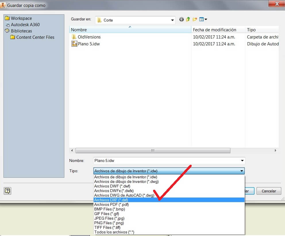
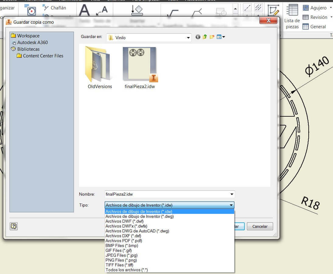
After that you should Save copy as, and choose .dxf (2004 or previous). Then import this file from CorelDraw to do the tests
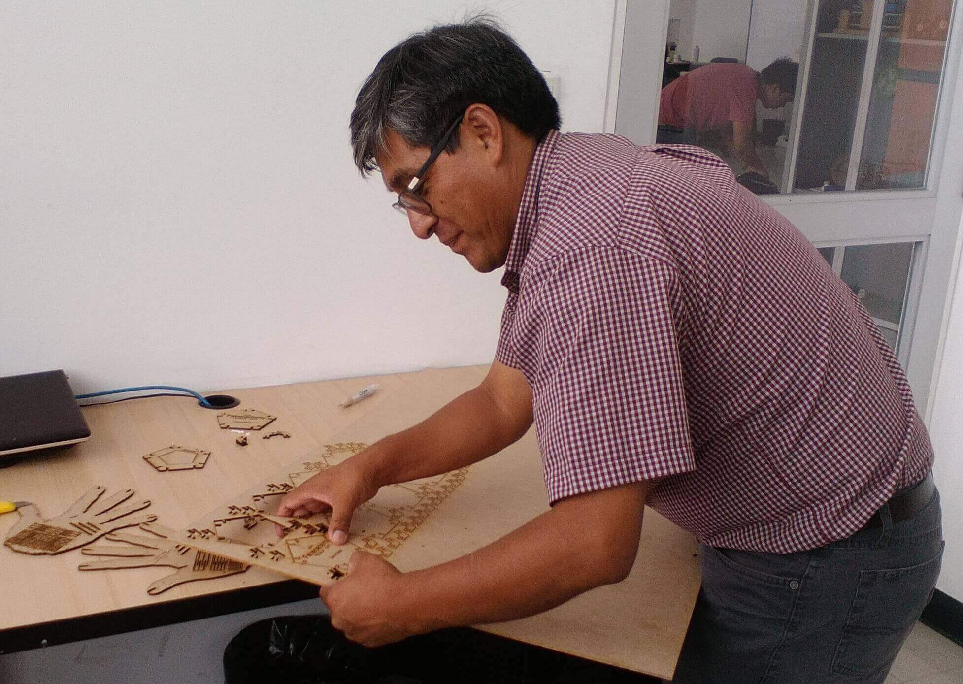
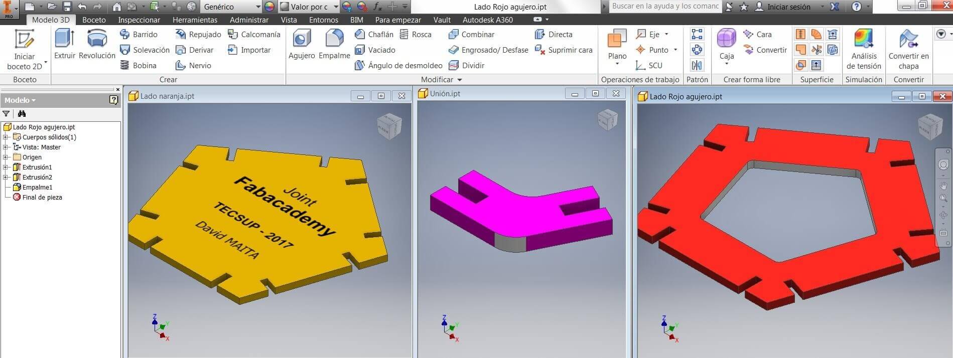
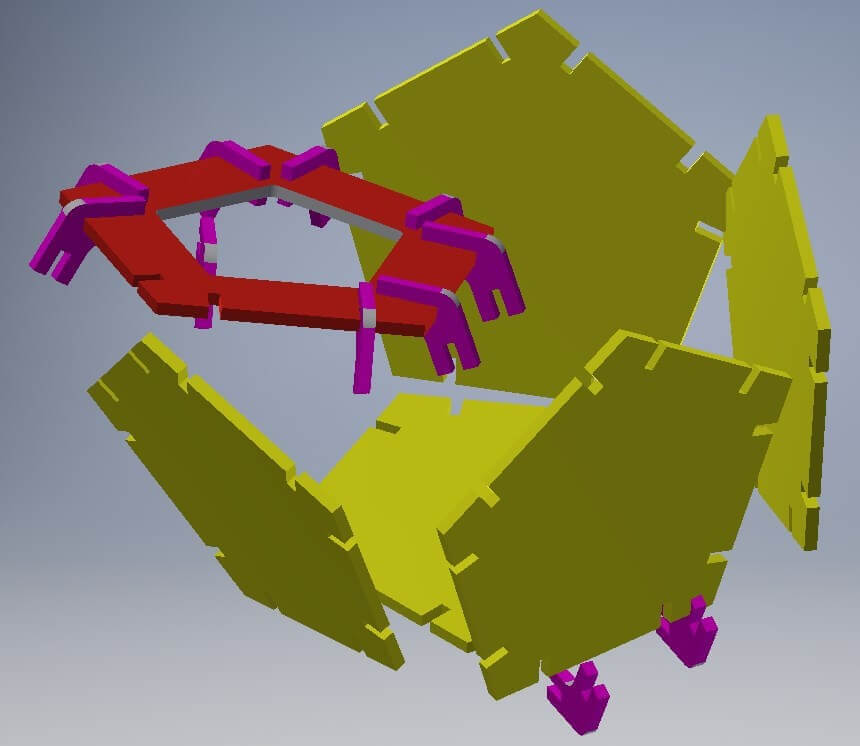
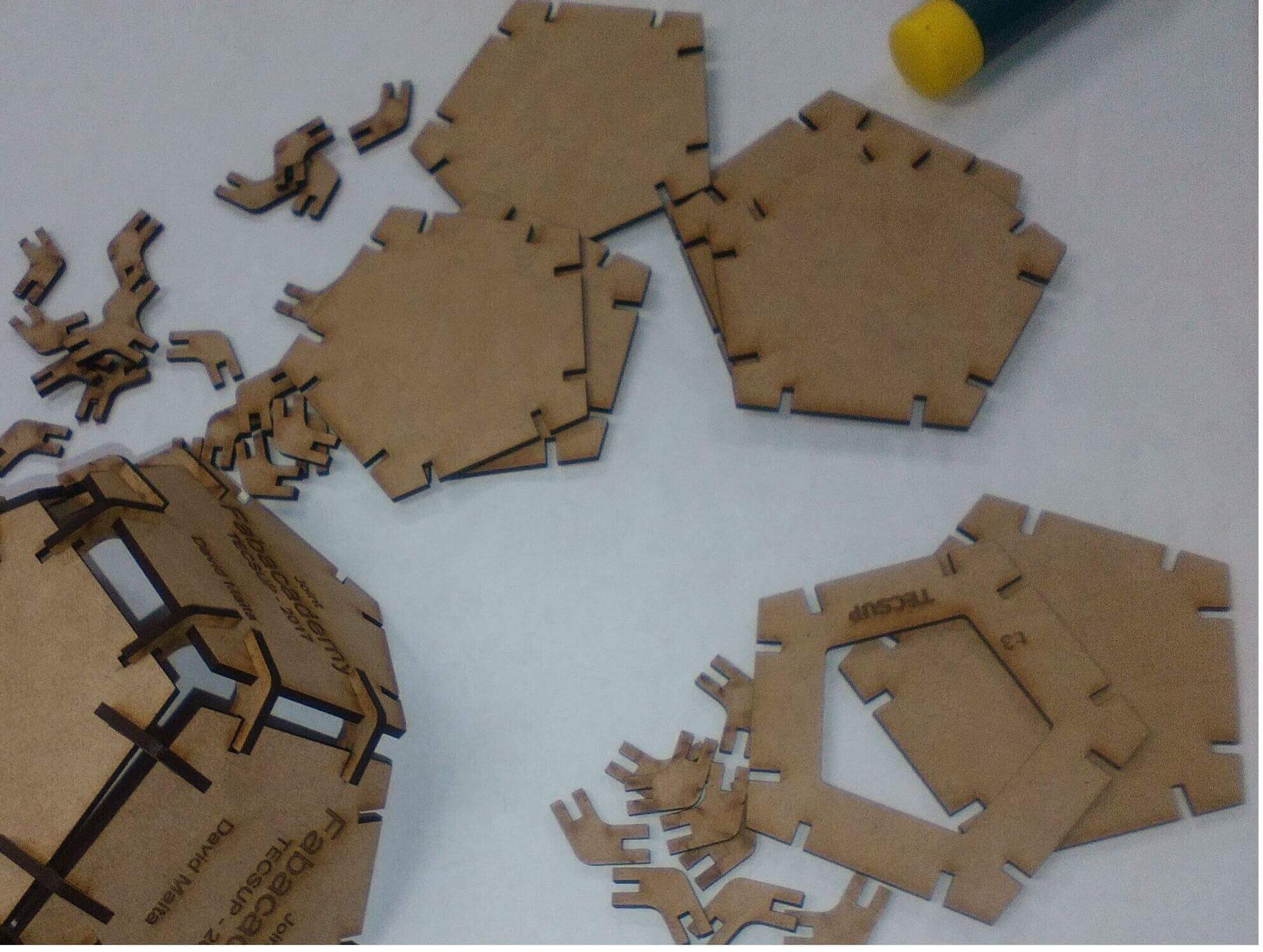
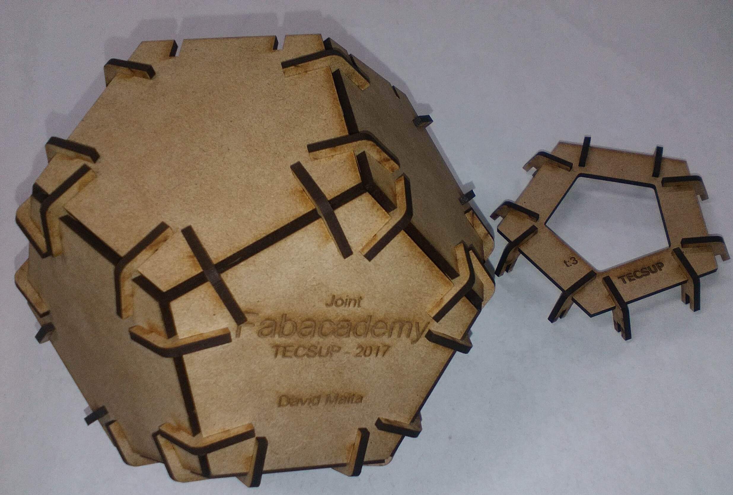
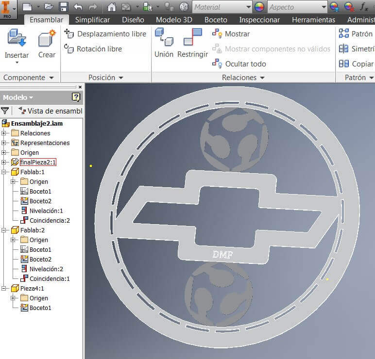
Do the assembly
Verify the file is in .dxf format, and impor it from Corel.
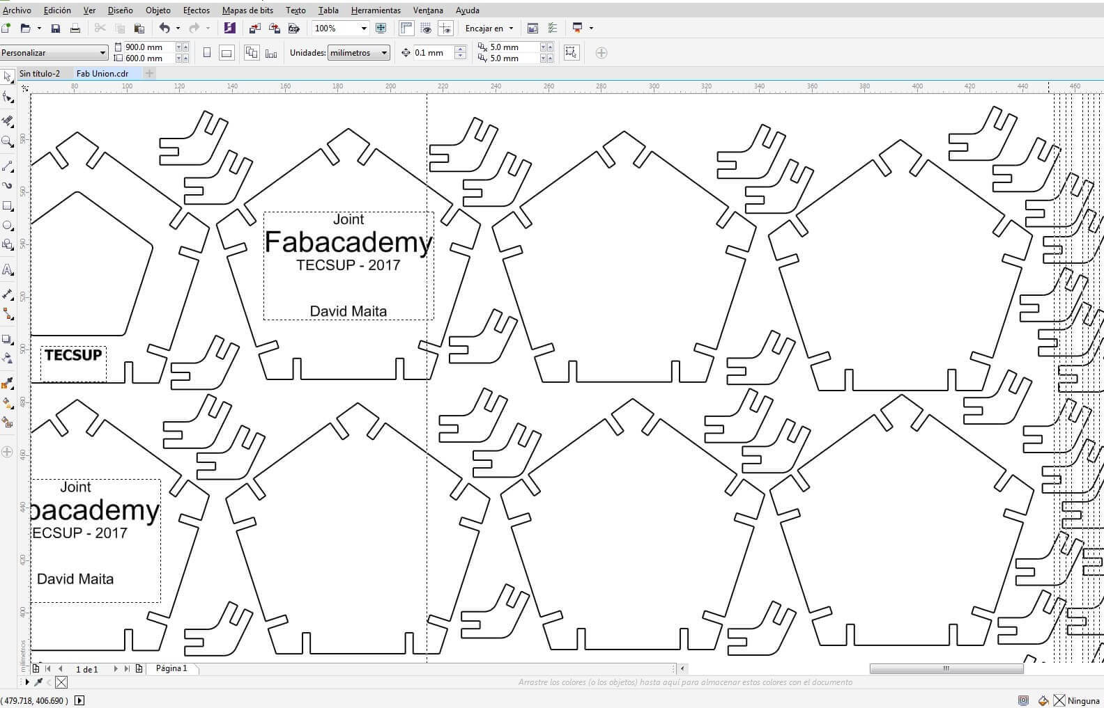
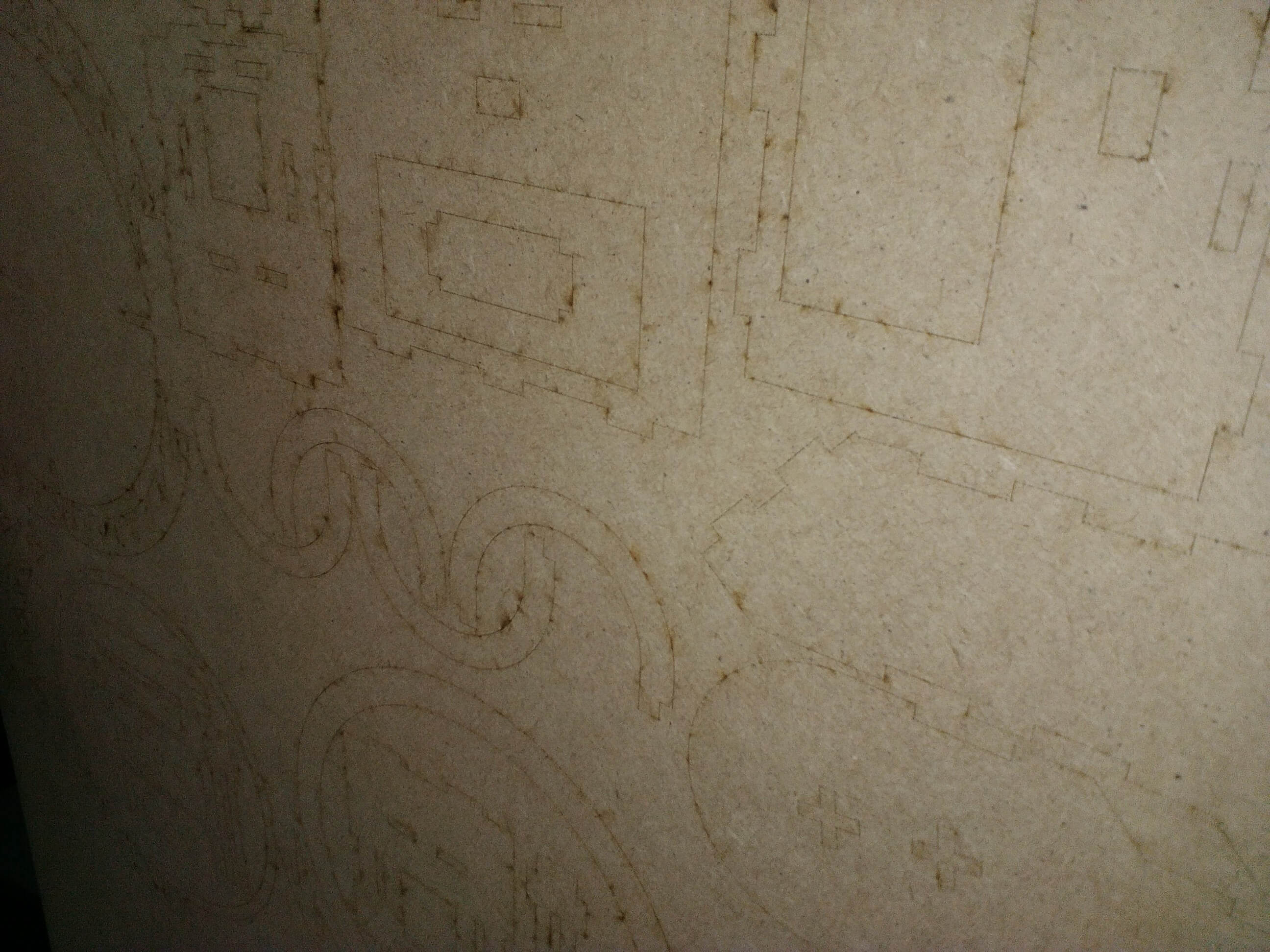
Note: First group the text and figures for raster and vector. Configure the raster on the software. Follow the numbers sequence.
Then configure the cut (contours are cut) and do the cut
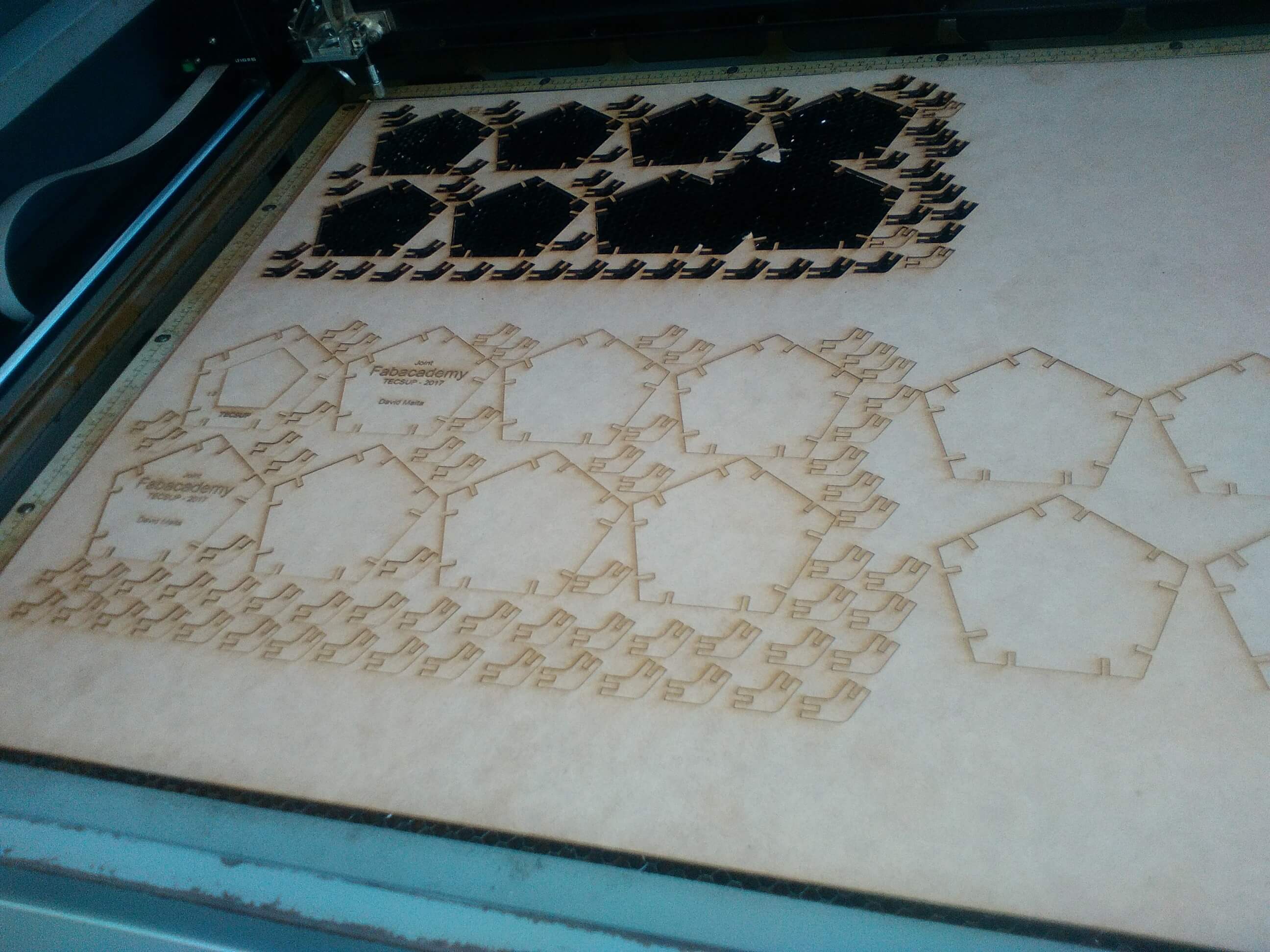
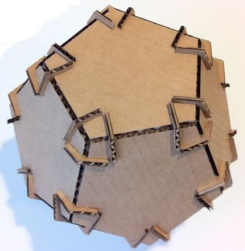
Once its finished pick the pieces and do the assembly
The cut was not complete since the MDF boards were not well stocked
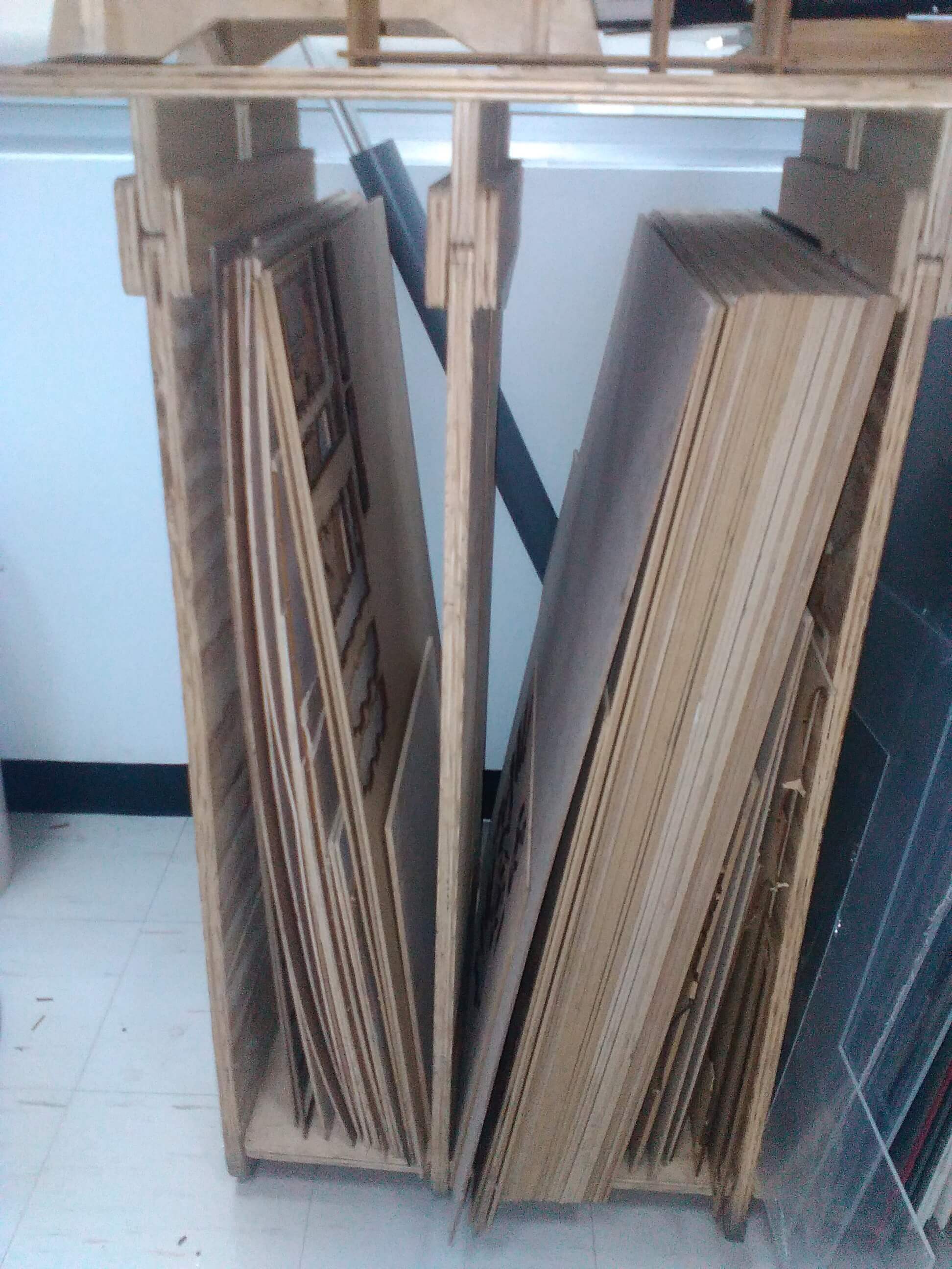
We did the cut too fast
Configure the MDF cut with the following parameters: speed 30%, power 90% Freq 500 Hz. It is suggested to stock the MDF boards on horizontal position

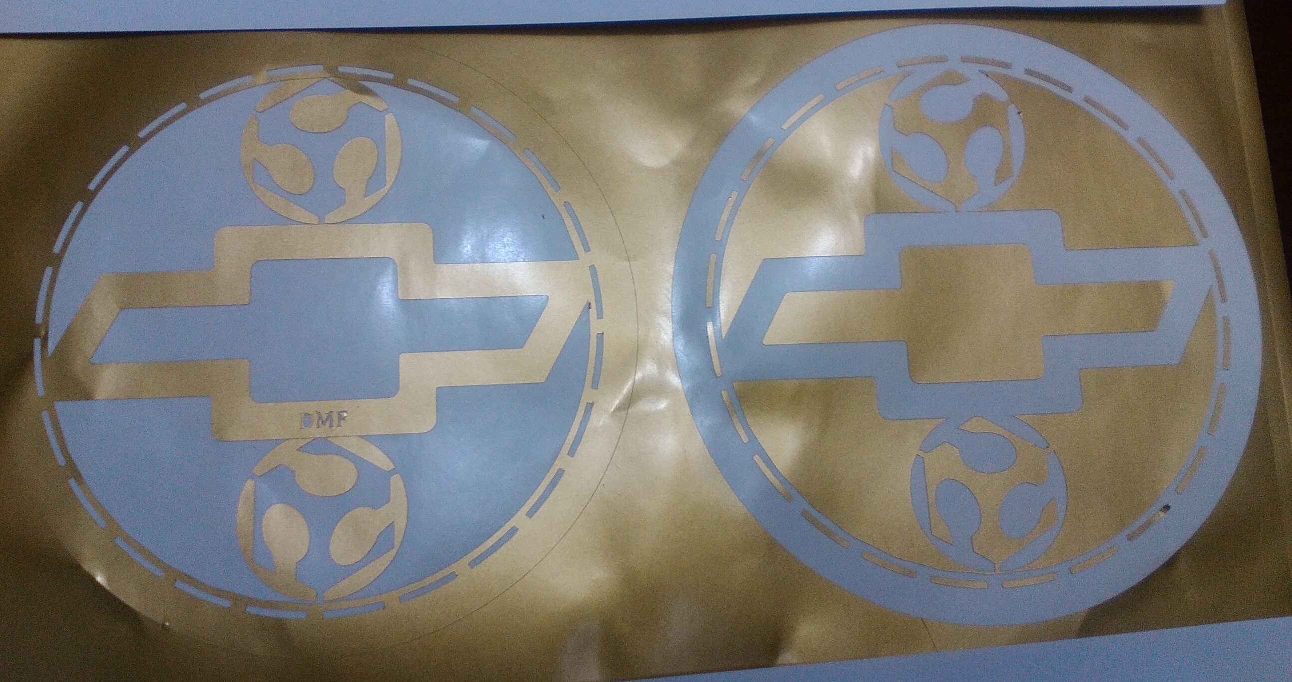
- Design and make a vinyl logo
- Demonstrate the vinyl uses
Select the figures to design


On inventor, design a sketch with its respective measures, following the 2nd week procedure.
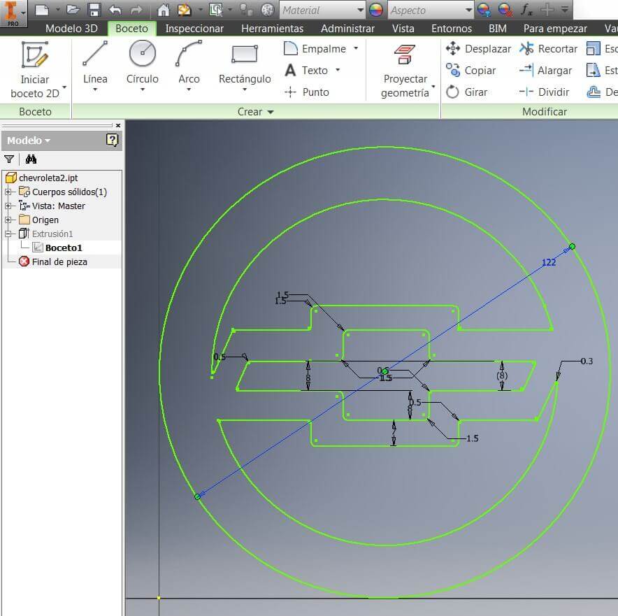
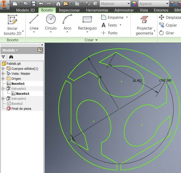
Then generate the extrude and the model
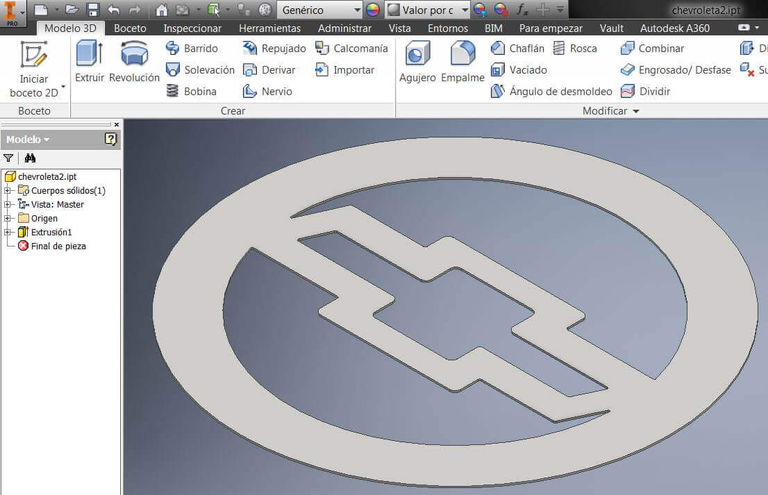
Then on inventor generate the working sheet to assembly according to the design. I made the plan and every object placement.
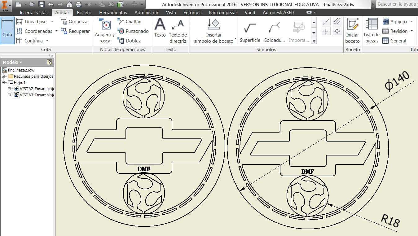
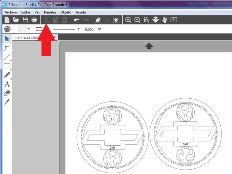
After the plan I removed the dimensions and saved the file in .dxf format so we can use the vinyl cutter.
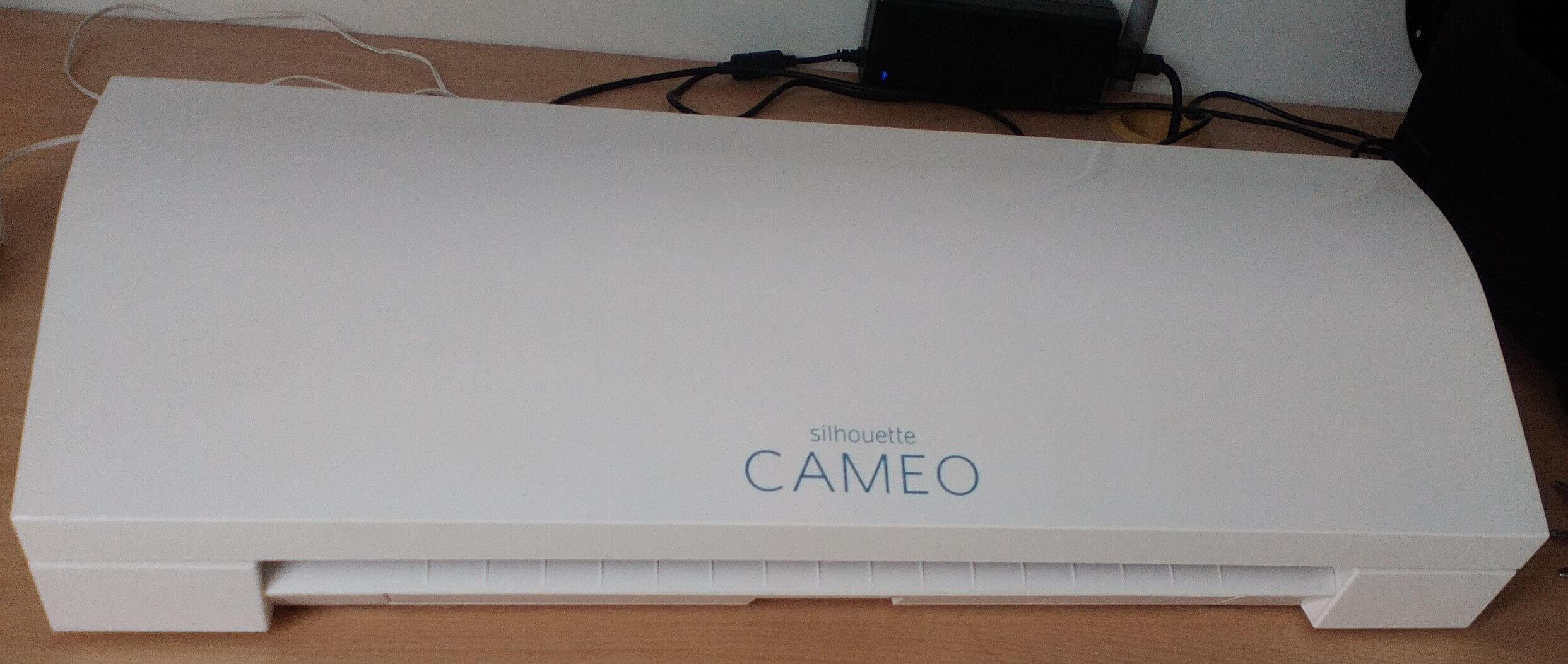
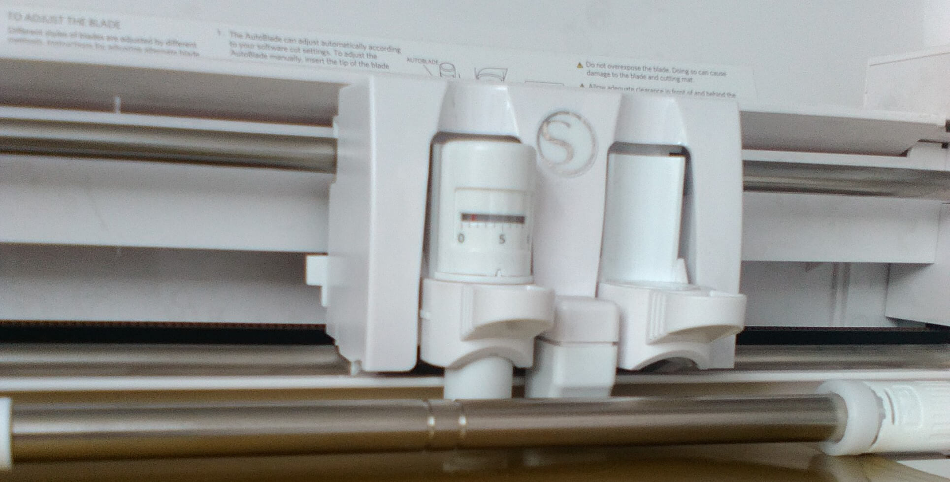
I am using a Silhouette vinyl cutter. Do the connections and check the dxf files. Check if the header has its cutting tool.
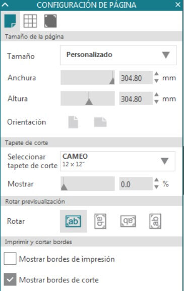
Open the vinyl cutter software and create a new workspace
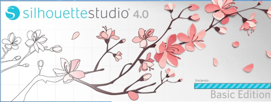
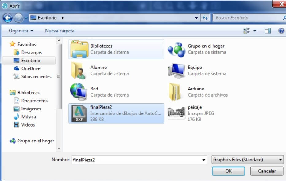
Import the file to cut and send it
Place the vinyl on the machin and press Start. Wait for the cut to finish.
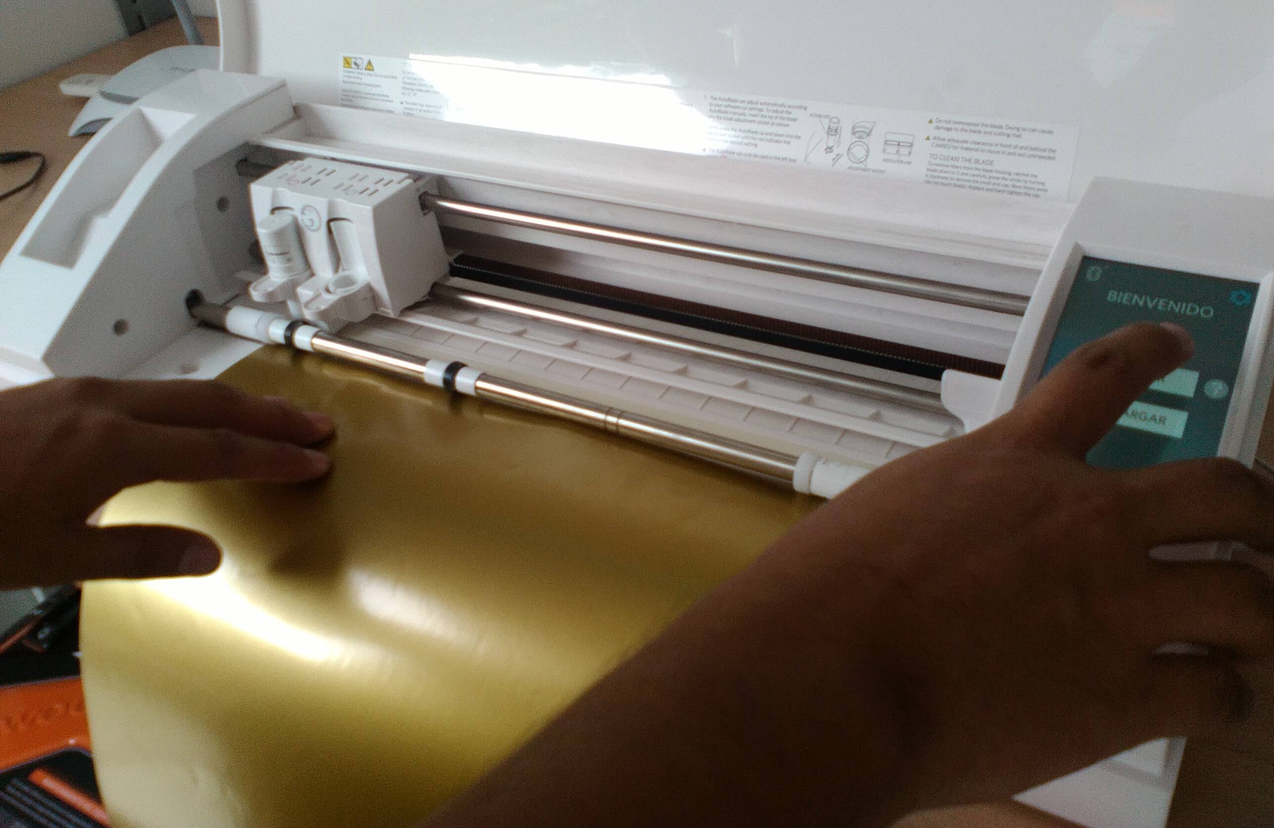
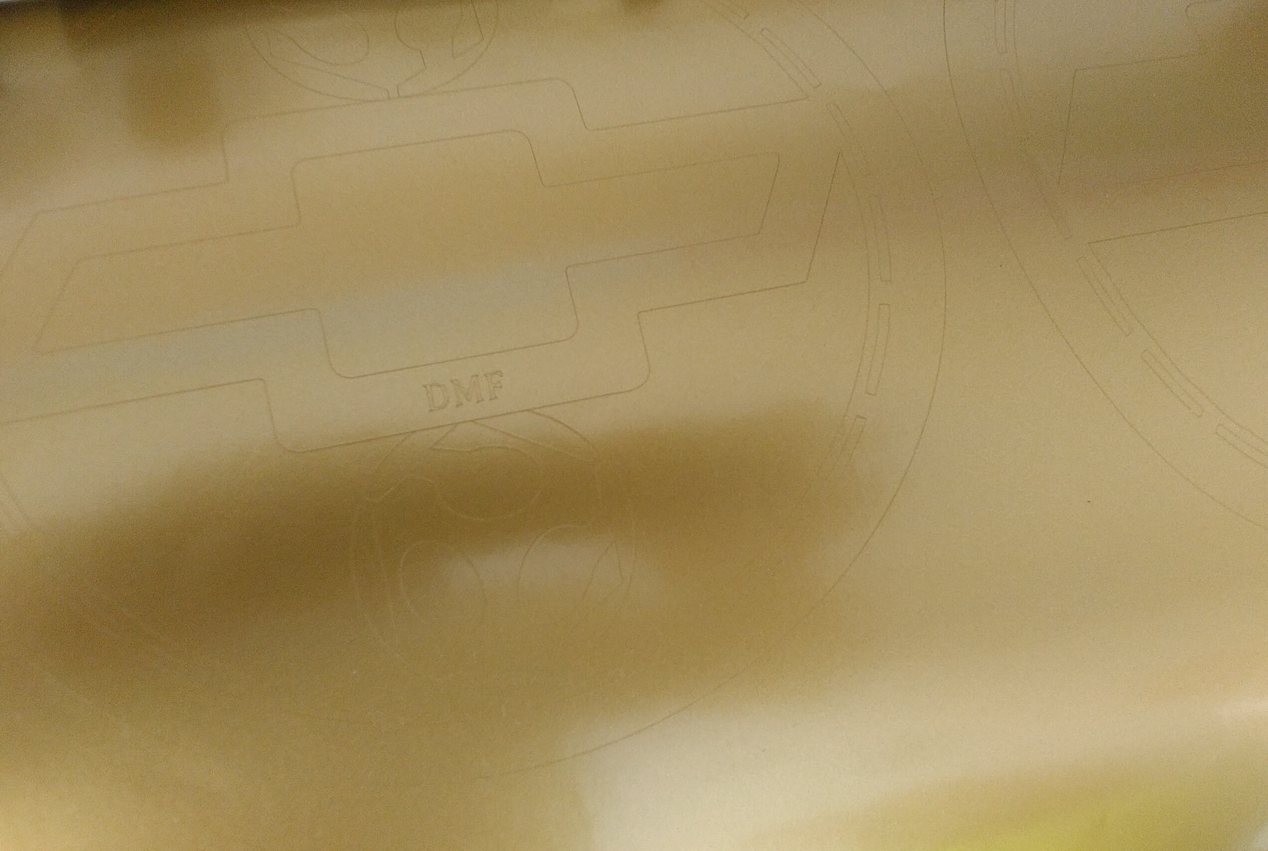
Wait for about 3 mins and pick the material
Now I have the final presentation
Check the video.
Here you can find the files