

- Evaluate and choose 2D and 3D design software.
- Demonstrate and show the process used on the 2D and 3D modeling.
- Evaluate raster and vector on different softwares
Gimp has tools that are often used to edit images, free form shapes, change size, cut, photomontage, convert to different image formats, and more speciffic jobs.
It is based on pixels, (little color squares) and its more like painting than drawing.
You can also create animated images on GIF and MPEG format using an animation plugin.
On most of raster images you can combine colors to do a transition between the different colors.
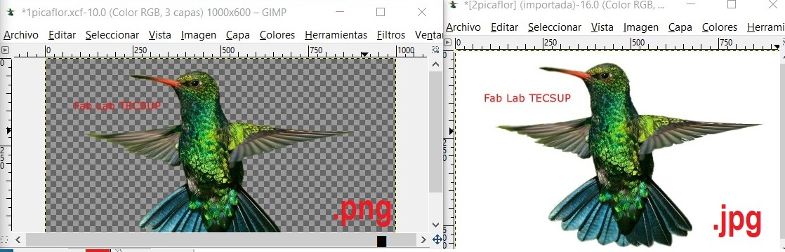
Raster images, also known as bitmaps images, are very common on the jpg and png formats, and they are used commonly for web.
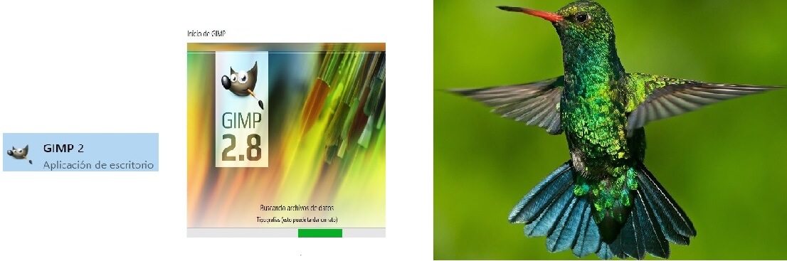
1. Open Gimp 2.8, freeware. Wait for a moment until it loads. I chose one of the peruvian central zone birds, from Huancayo - Peru.
Then you will see the working space of Gimp. If you see it on blank, go to the tools bar, Windows and activate the Tools bar and the Layers bar. Then you will see the tools bar on the left and the layers bar on the right.
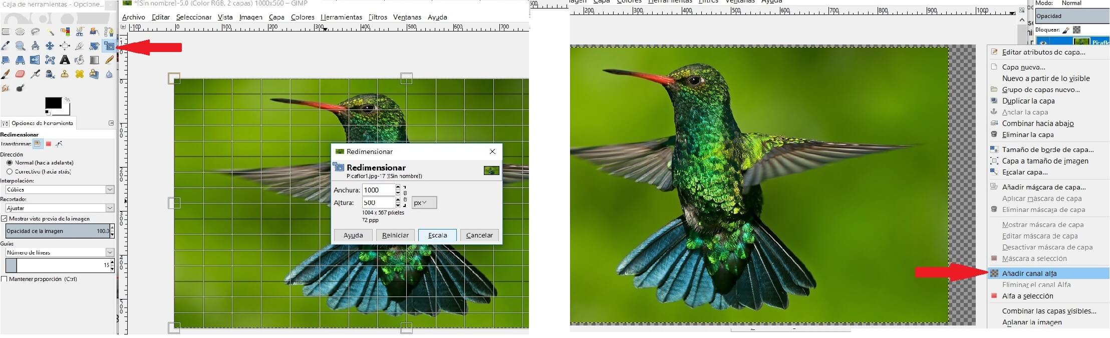
After that I opened a new work sheet using the dimensions. You can decide the position as horizontal or vertical on Transparency. Then drag the figure on the canvas, and scale it to the canvas.

Then I resized the bird on the canvas. Now on the layers right clic extend and fix using Add alpha channel
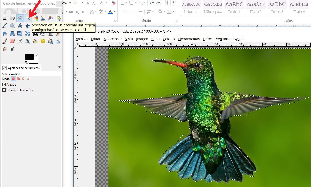
Now use the tool Difuse selection (U) and delimit the bird, then use de Delete tool to erase the bird's background.

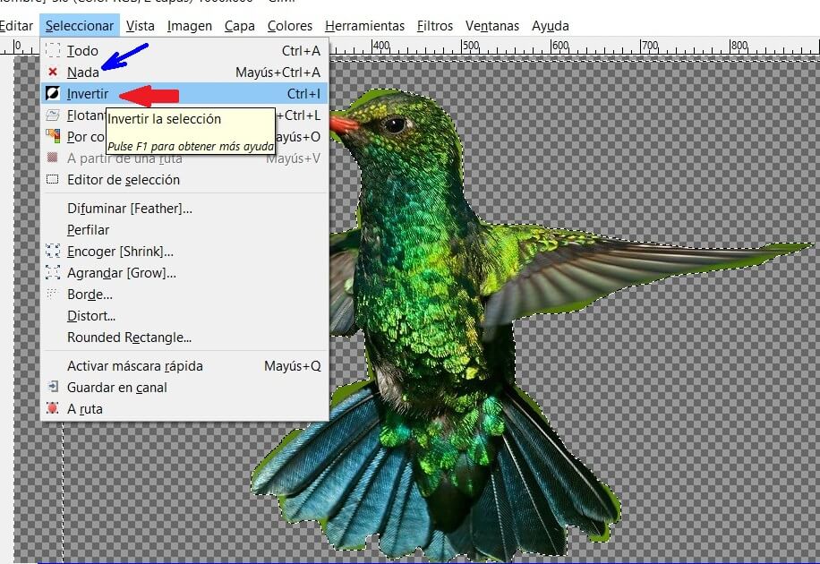
If you have deleted the background you can place the bird on another background. Now you can use the toolbar, tool select, and Nothing. And if you want to delete the external part use the select tool and the command Invert. Again use Delete key.
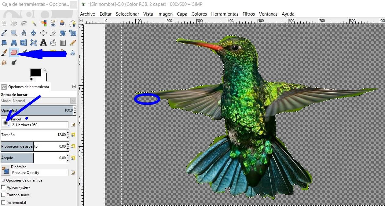
If you need to correct the borders, you can use the Eraser and select the shape and size of the brush.
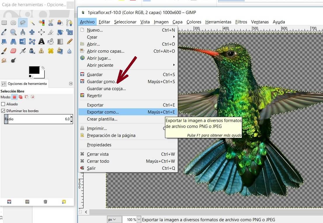
Now you are ready to take them to raster. First save the image as .xcf (GIMP). To upload the file to web you should save it as .jpg or .png, a little bit heavier formats. For this you need to use the option Export As
This format is different from the bit maps. In this case we use vectorial graphs, instead of pixels. So when you scale the image, you wont lose quality. It allows you to move, scale, and modify images in a simple way. It also is used to generate dinamic and static images.
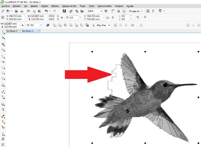
I used the work space configured to match the machine, an 600 x 900 mm area. I imported a bird's image on the workspace and you can modify the image as you want.
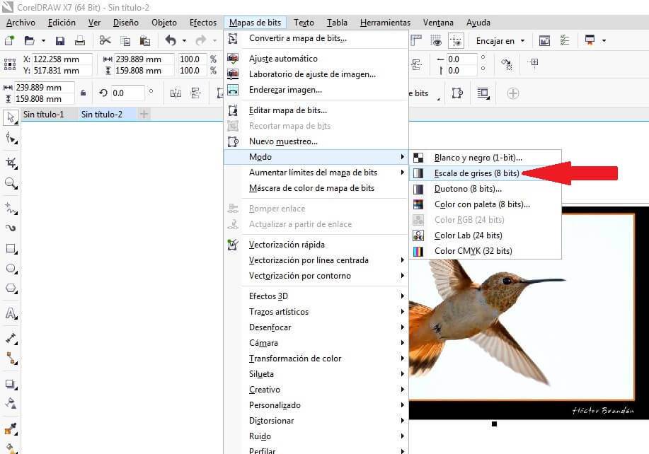
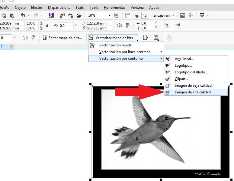
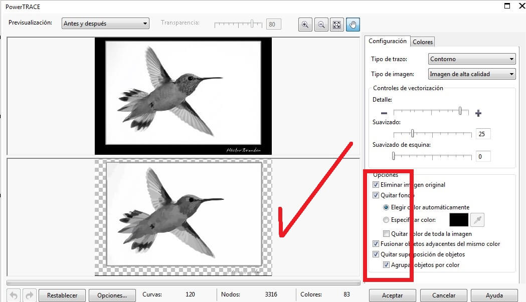
Open the toolbar Bitmap and choose the Mode command and pick grayscales (8 bits). Then use the command contour vectorization and chose High quality image. Verify the configuration and remove the background from the bird's picture, as I show below
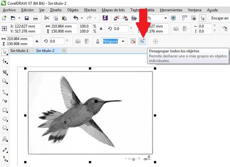
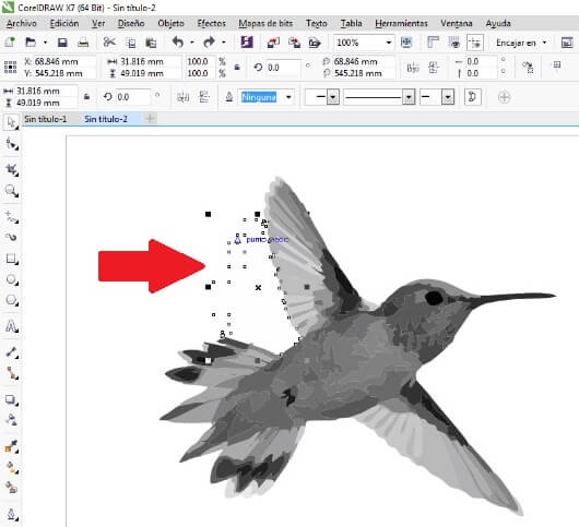
Then I use the Ungroup command to delet the background from the picture.
Cofigure the bird's raster
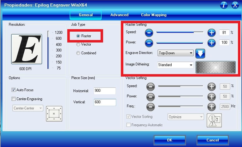
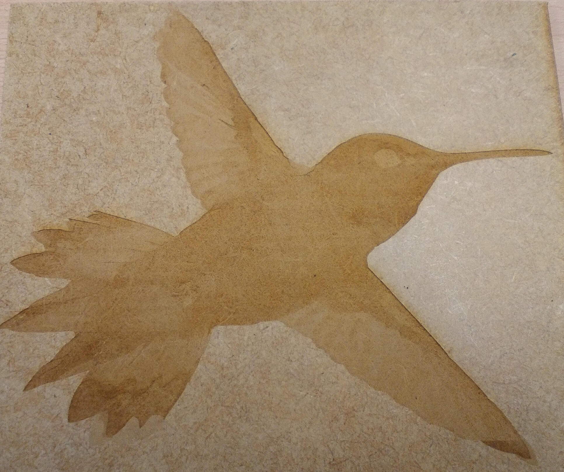
I made the raster on 3mm MDF
Copy the bird, but this time show the borders using the tool Color palette.
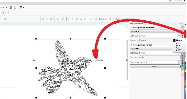
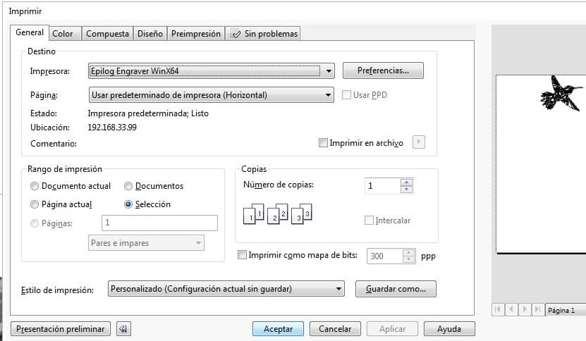
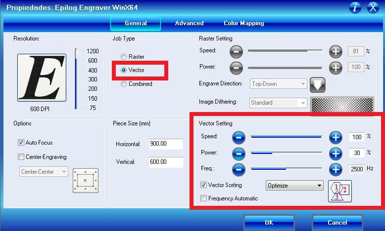
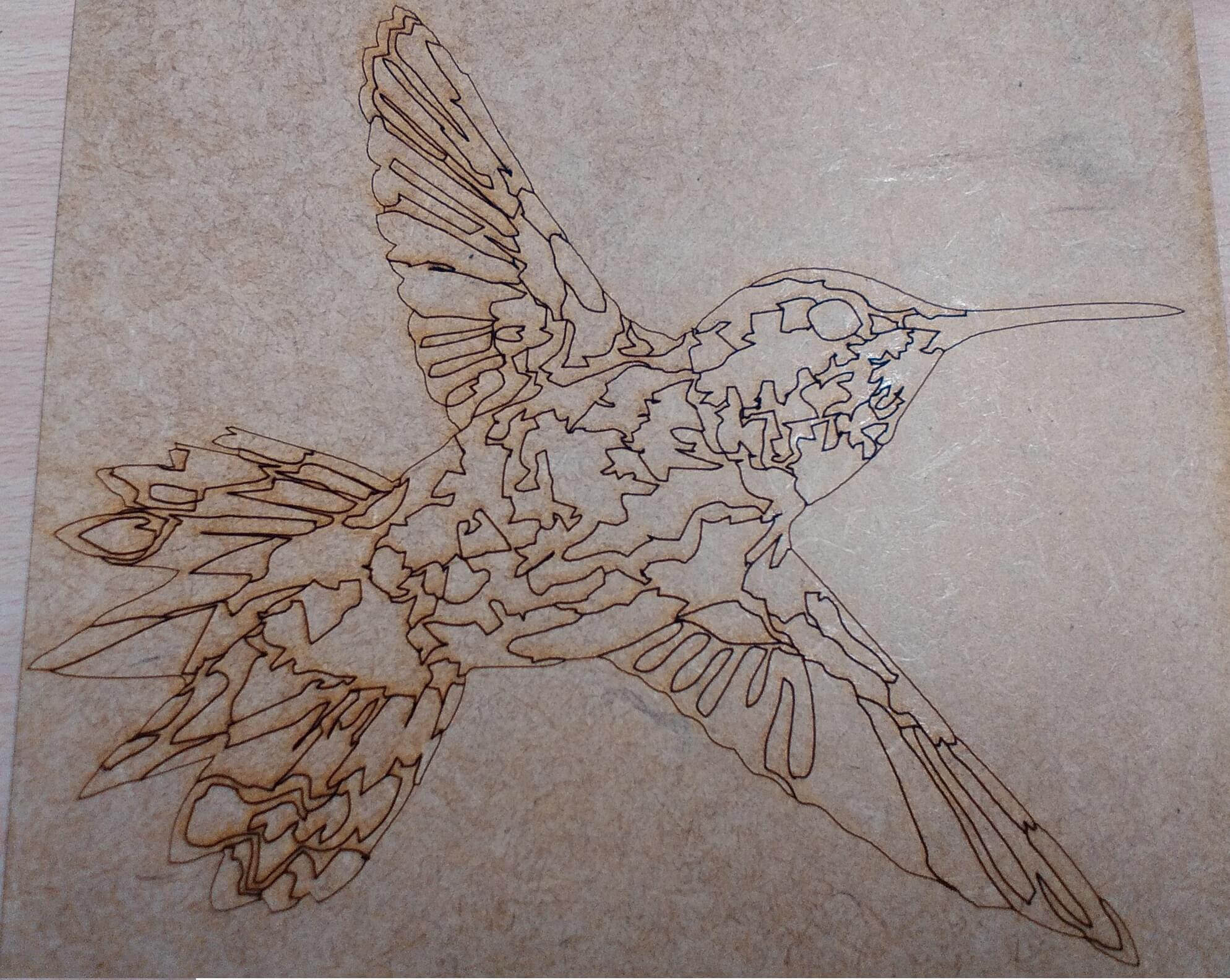
Configure the vectorization parameters: speed 100%, power 30% and frequency 2500 hz. I made the vector on 3mm MDF.
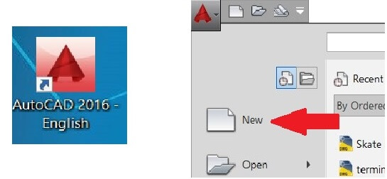
For my 2D drawings I used Autocad, first I generated a new sheet.
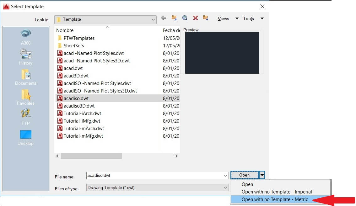
Then I selected the sheet without frames (acadiso), and the metric units. After that I configured the layers for drawing.
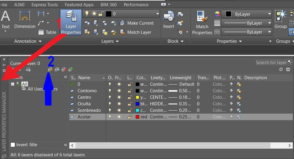
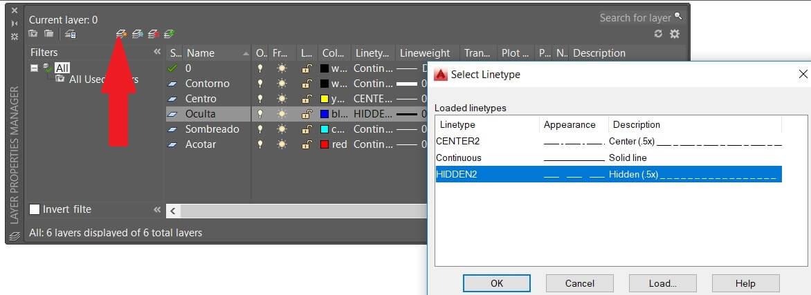
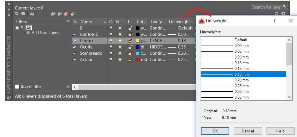
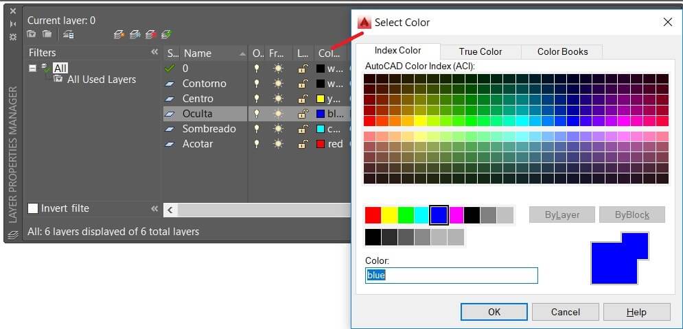
Here I generated the line types, thicknes and color according to the international standar. Now we are ready to draw.
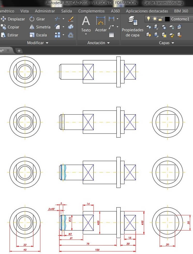
Do the drawing using commands like Line and activating the Orto mode (F8), and follow the rules to generate the views of the element you are drawing. This software allows us to generate 2D fabrication plans.
Note: This software is very difficult to use in its 3D version. For 3D design I use Inventor.
Once you draw an element you cant modify the measures, and you have to redraw
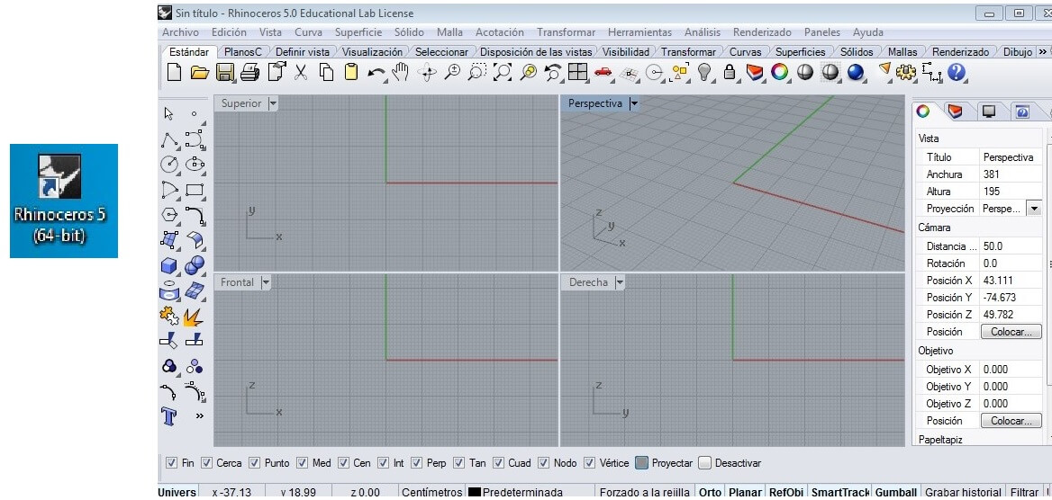
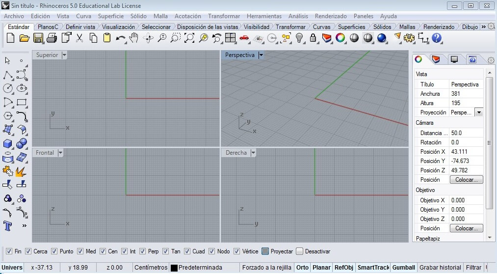
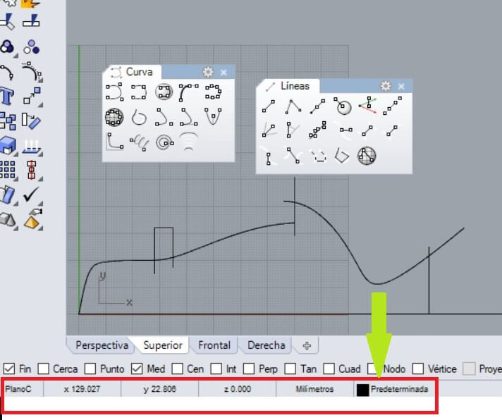
Open the rhinoceros and observe the workspace
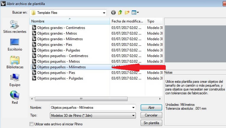
Create a workspace and choose Small objects in milimeters.
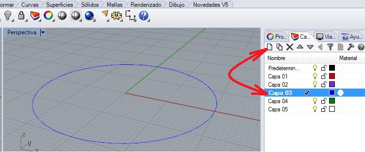
Then I generated the layers to recognize the different type of lines to draw. I started drawing considering the measures showed on the workspace.
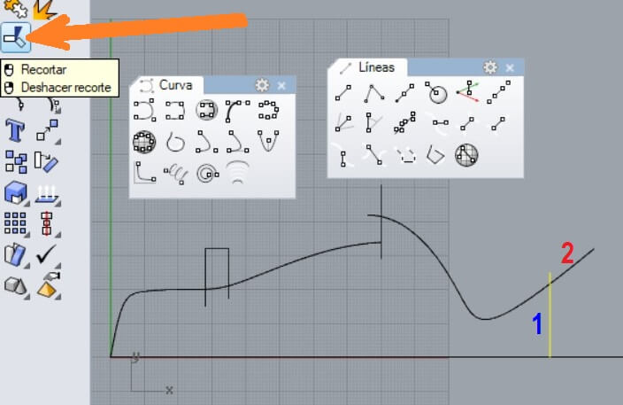
After that I trimmed the excess of lines and arcs as I show on the next figure. After trimming you have to group all the object.
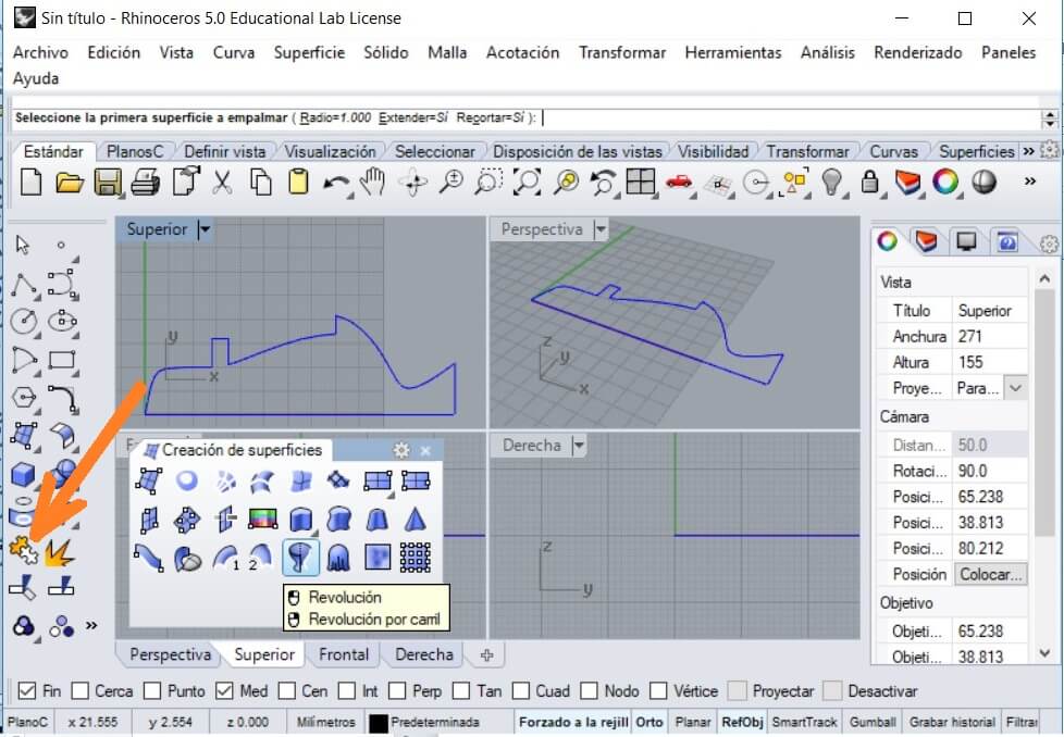
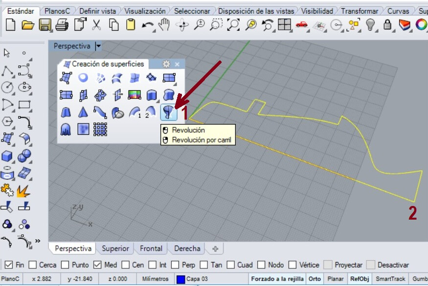
Select the Revolve command and use the mouse to clic on the left side as the command recommends. You have to select the object and press enter to select the simetry line. The initial angle is 0°, enter and add the revolution angle (360) and finish by pressing enter.
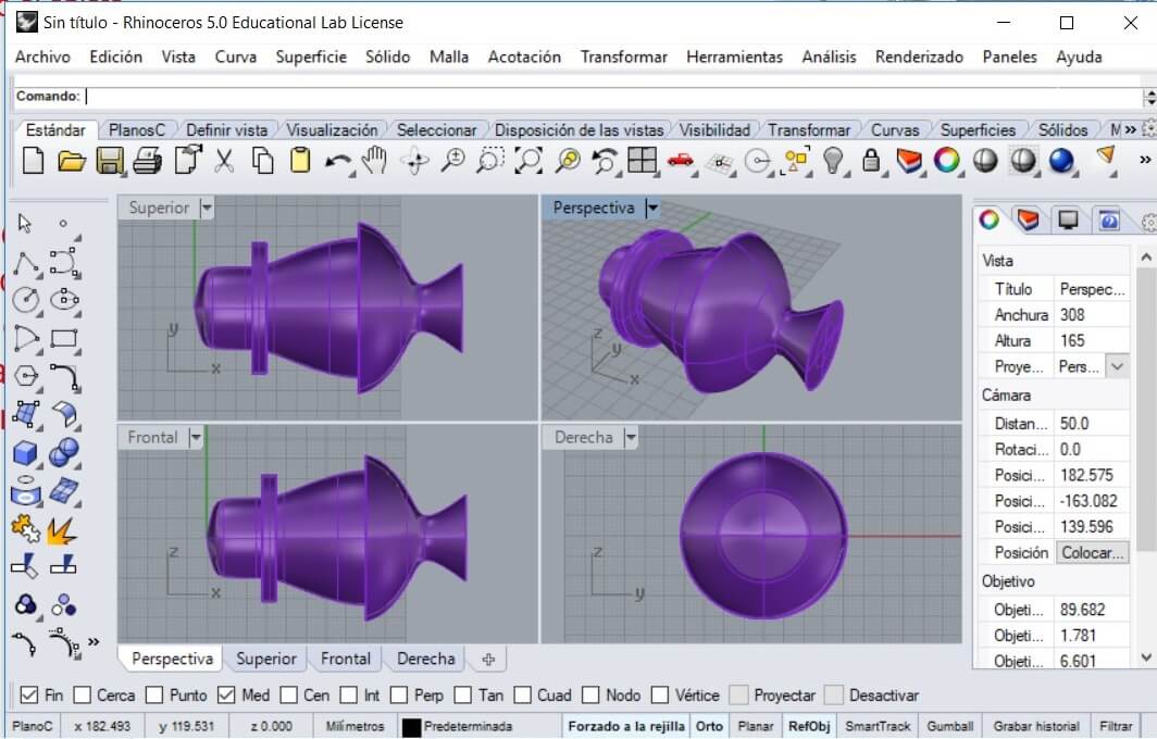
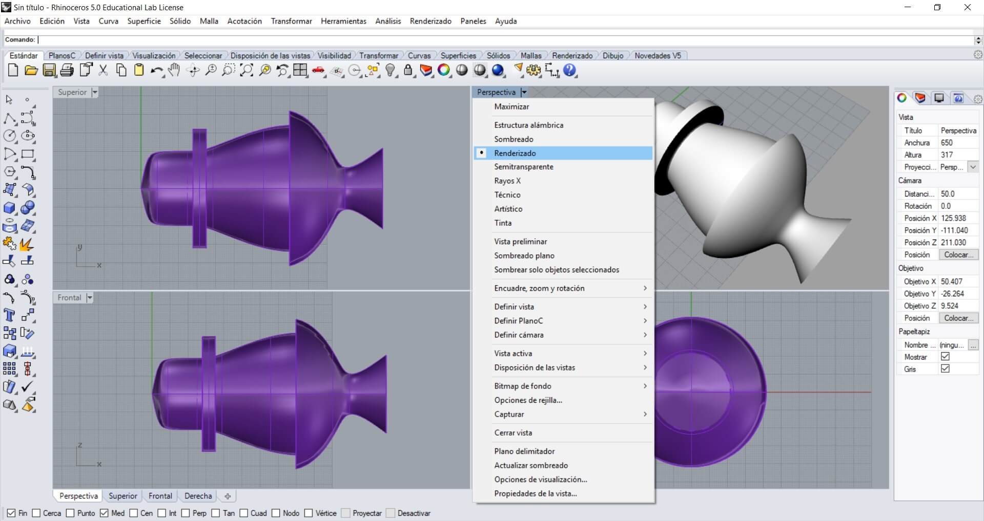
Apply render to the object to see its final form.
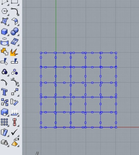
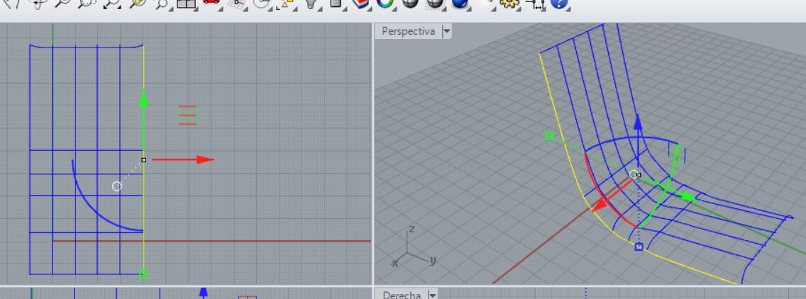
Draw lines and use the Reconstruct command. Then use the Activate points to move the points as I show
Then on the top view I was able to select the points. Also using the lateral and the perspective view I made the modifications until I got the shape I needed.
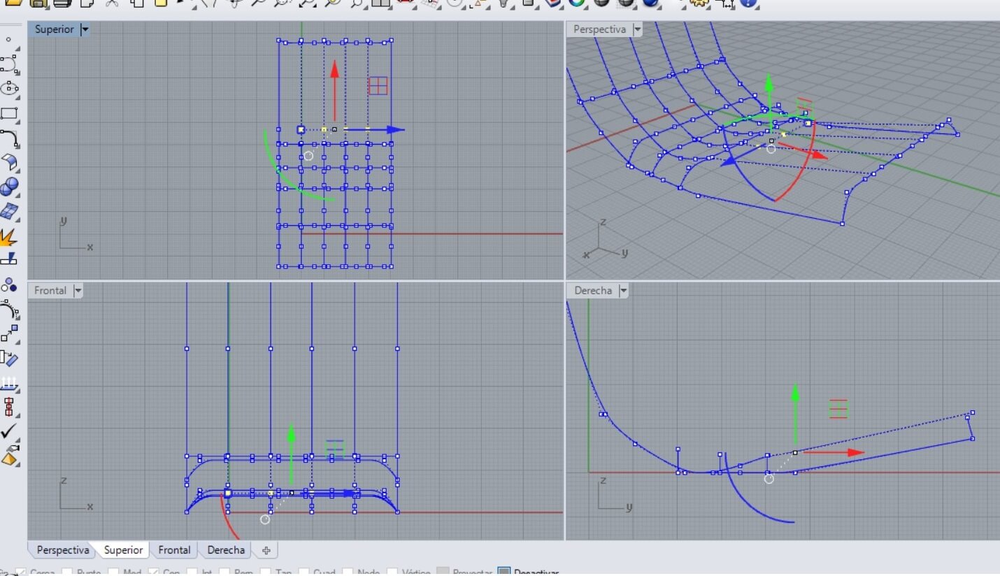
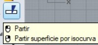
A mesh needs at least 3 or 4 free lines. In my case the lateral sides were larger, as I show. I used the Break command and after you select the line and press enter, you have to select the point option to place it on the intersection, to partially separate the line.
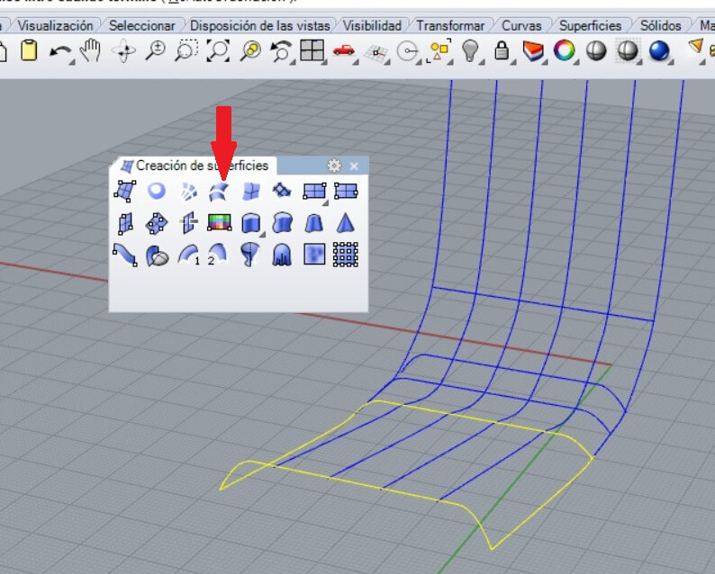
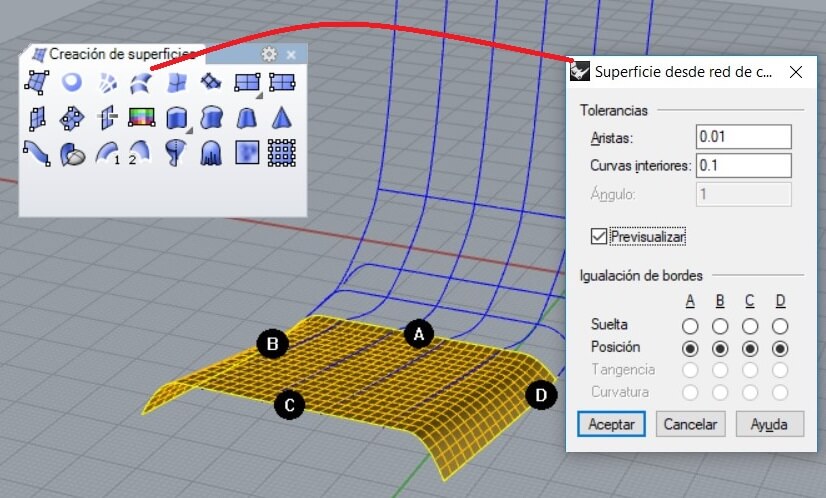
After that I selected the command Surface from 2, 3 or 4 edges and press enter. I chose previous as the mesh shows.
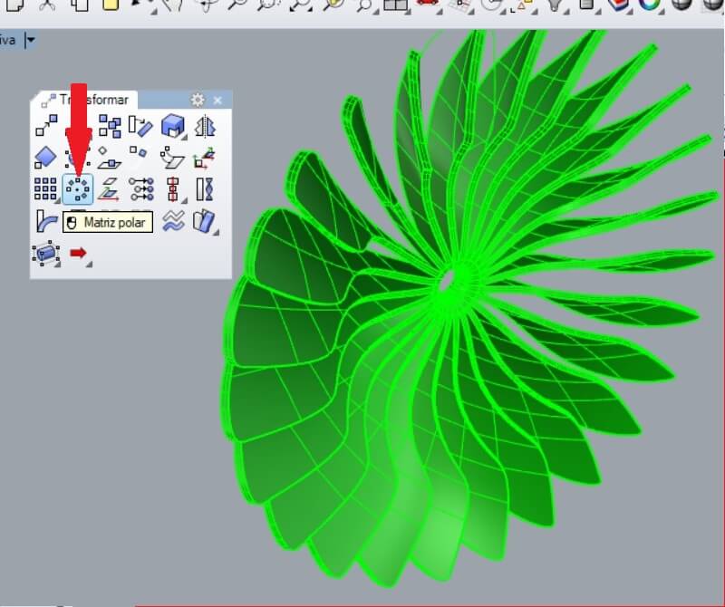
For example for the fan after drawing a propeller I used a polar matrix and then grouped and join the parts
Then I made the assembly and the perspective render.
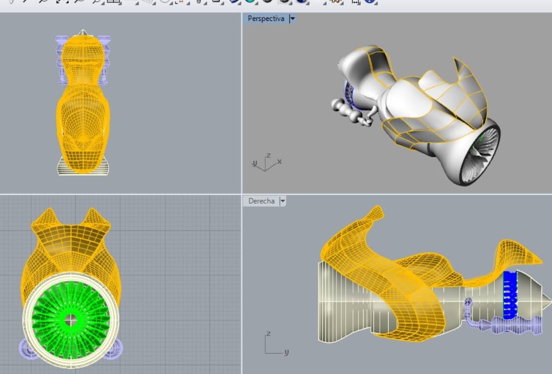
It's too laborious working with mesh and solids.
This is a mechanic design software.
- Allows free shape modeling, in a parametric way. It also has tools for views and simulation.
- Generates a view using the comercial material, and shows it as a simulation.
- It simulates rotative and linear movements.
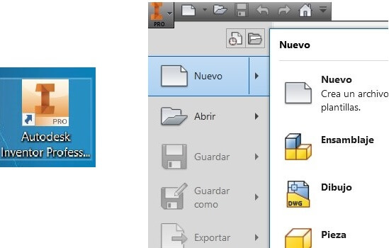
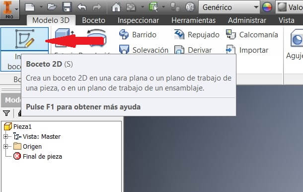
Open the software and create a new file.
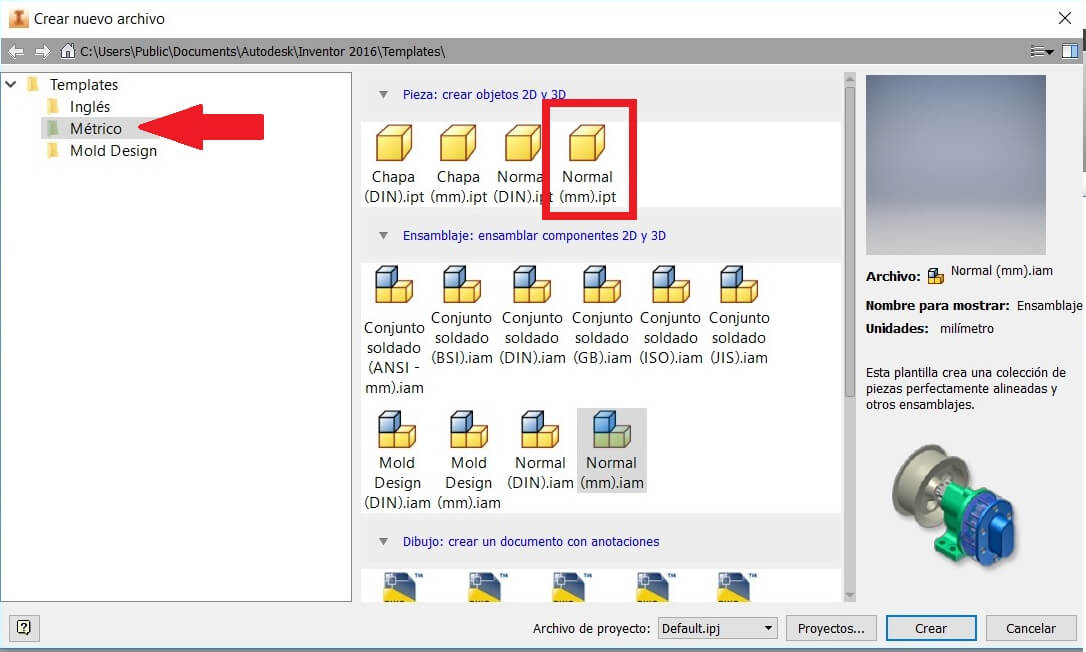
Select the units to work, and the file on format .ipt. Also clic on New sketch
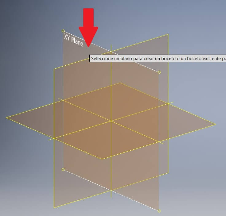
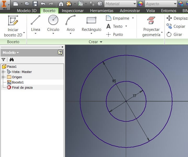
Pick a plane on the software. Then draw the sketch, in this case made of 2 circles, of 37 and 85 mm
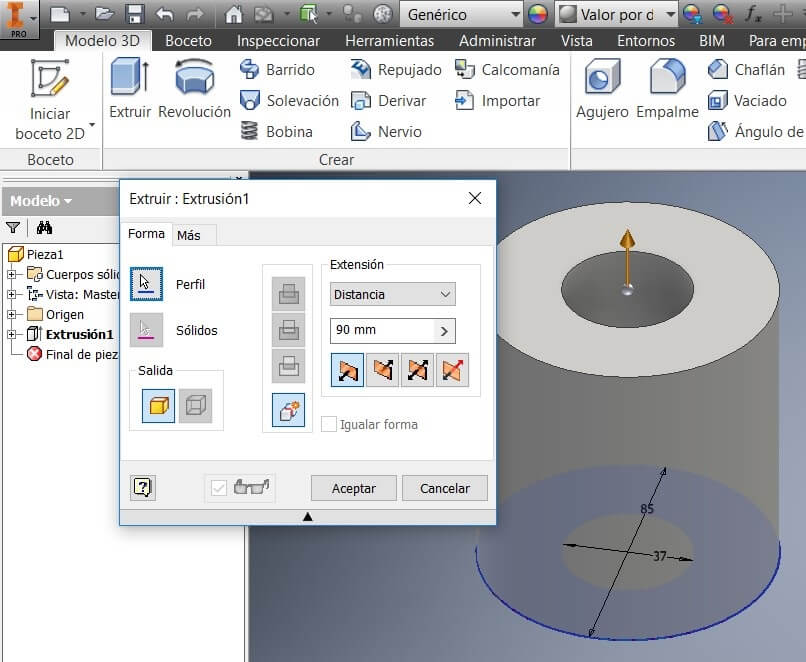
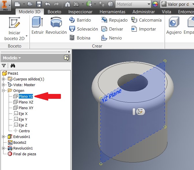
Then I extruded a cylinder generated by the 2 diameters. Then I chose the YZ plan and made another 2D sketch
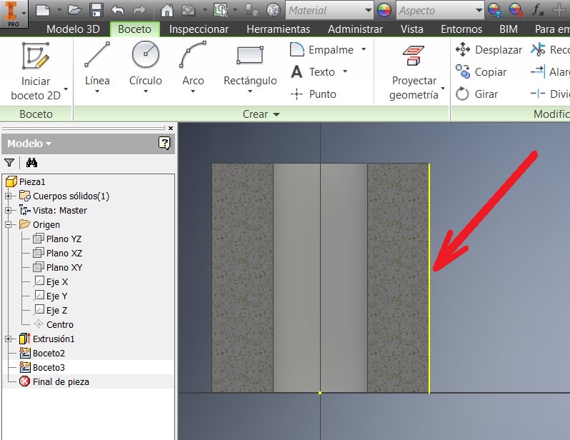
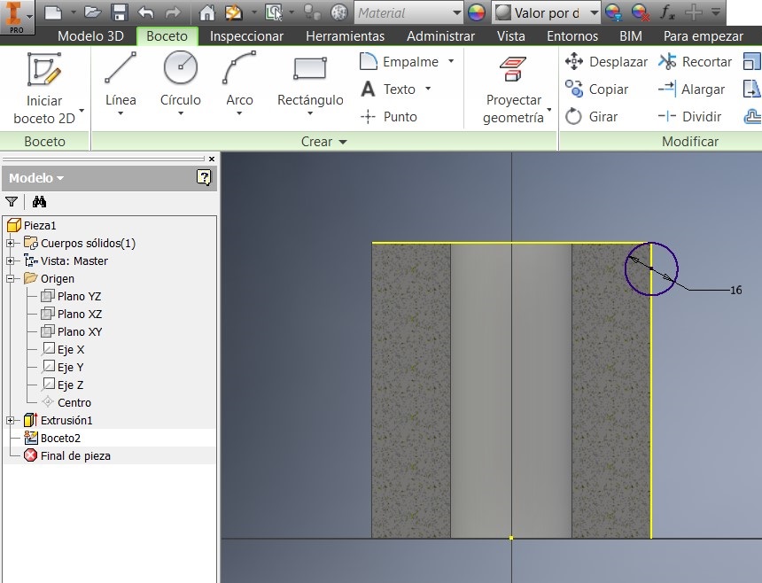
After that I pressed F7 to see the imaginary cut. I made a Geometric projection on the line and draw a 16 mm circumference
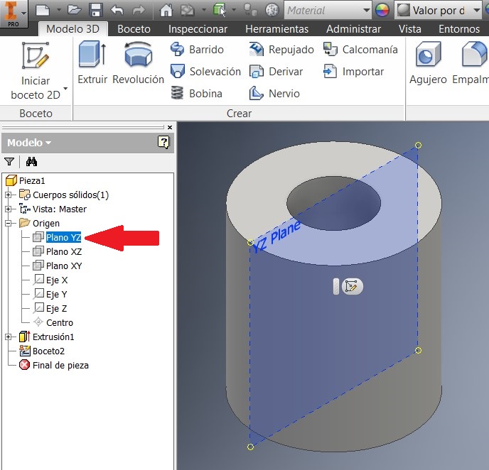
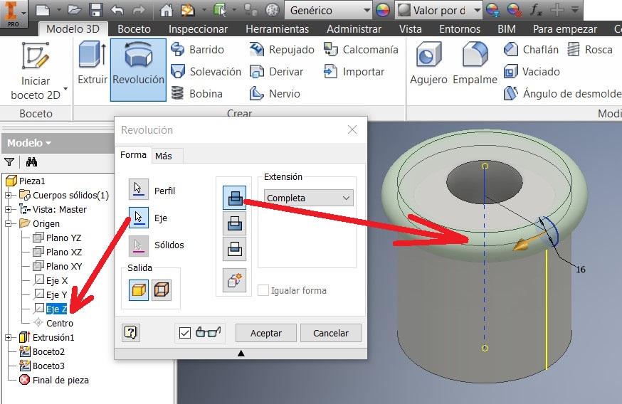
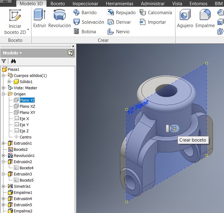
I used the revolution command and I chose the Z axis on the Browser. Then I chose the YZ plan to made another sketch
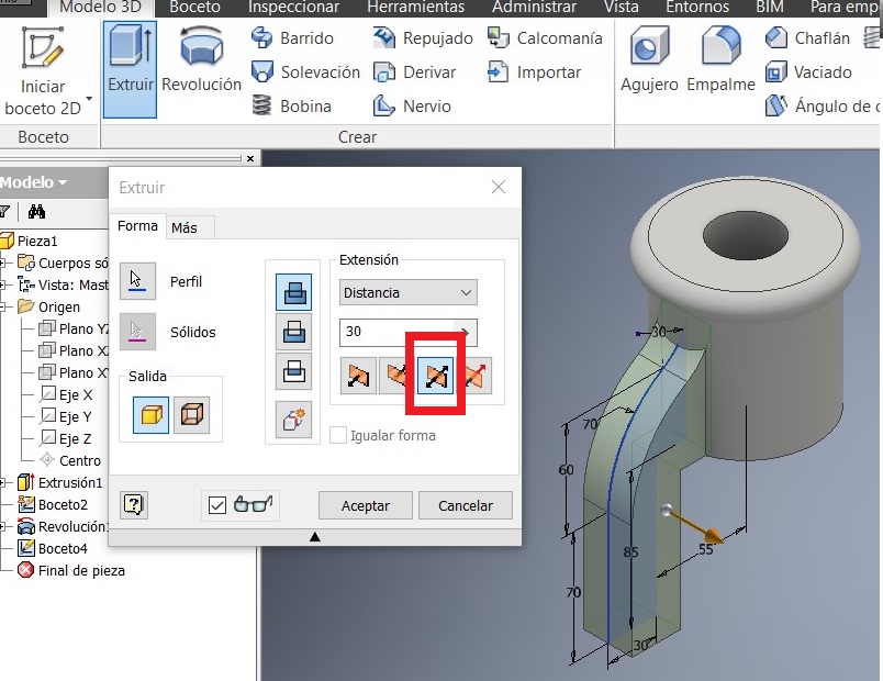
I pressed F7 to see the imaginary cut. Then I extruded both sides about 30mm.
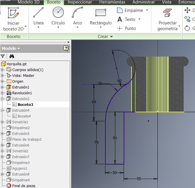
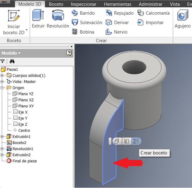
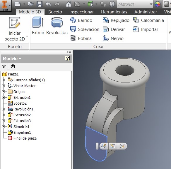
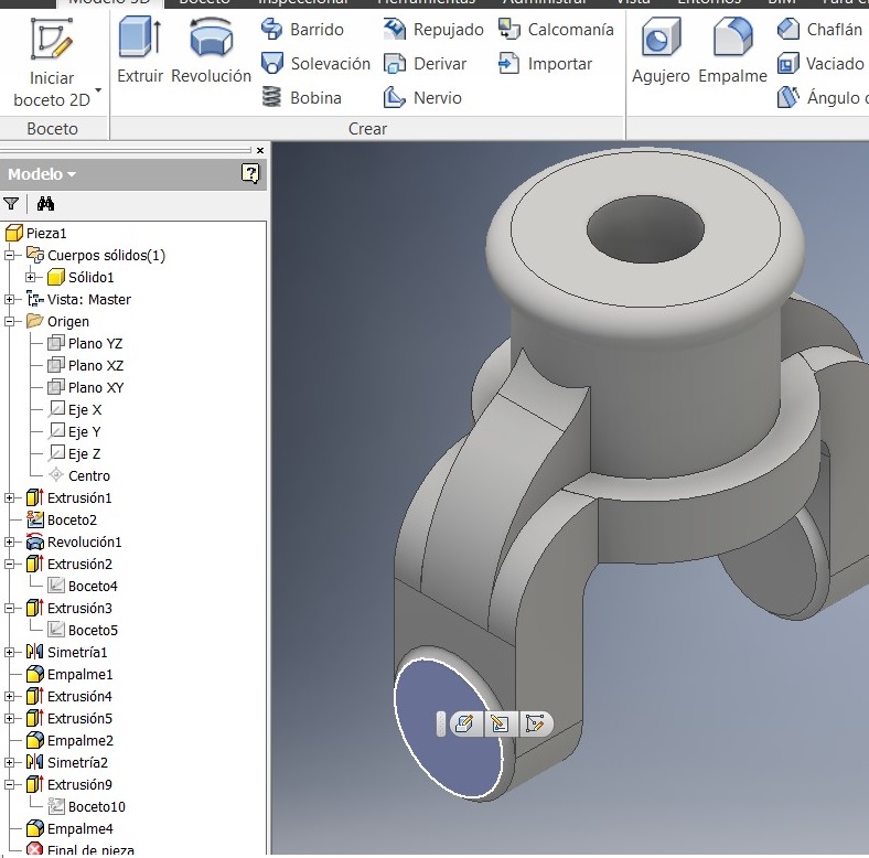
After that I picked this side to generate another 2D sketch. I made here something to strengthen the piece.
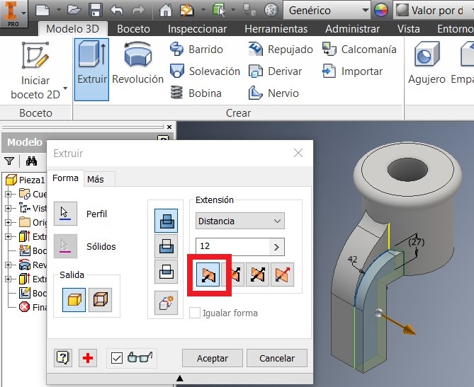
Also I extruded a 12 mm distance this sketch. Then I used the simetry command to strengthen also the other side.
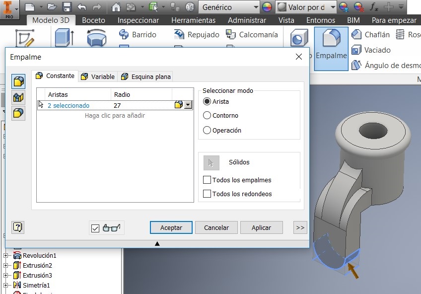
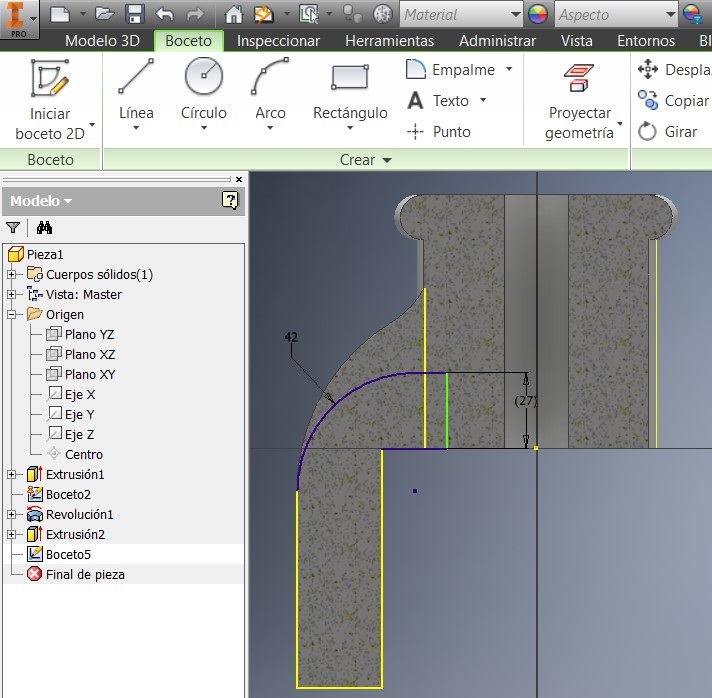
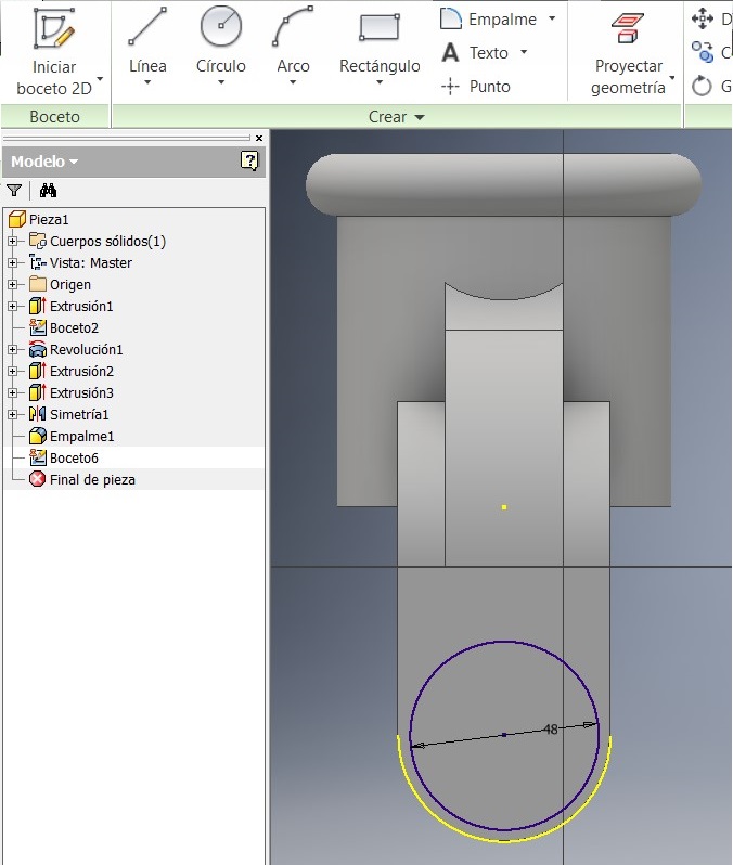
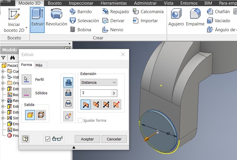
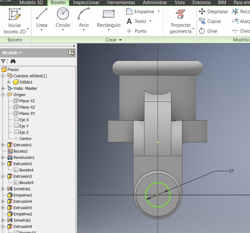
After that I used a command to generate the 27mm radius, and to make a circle Draw a 48mm diameter and verify that both circumferences are concentric, and extrude them 3 mm
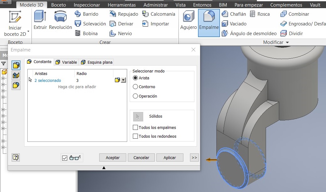
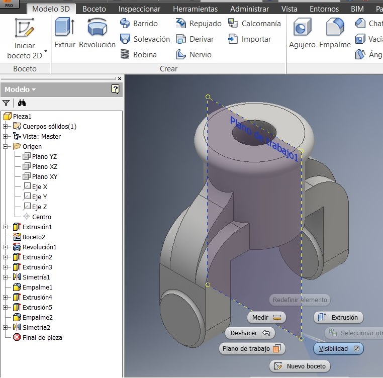
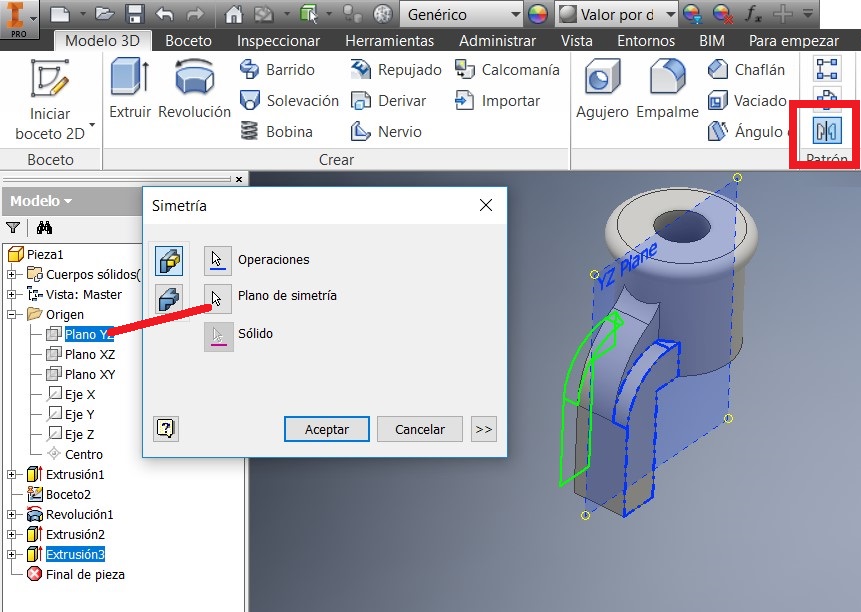
Also added the 3mm radius. Identified the simetry plan and activated another plane click on XZ plan.
Then I used the Simetry command where I selected the objects and made a new sketch.
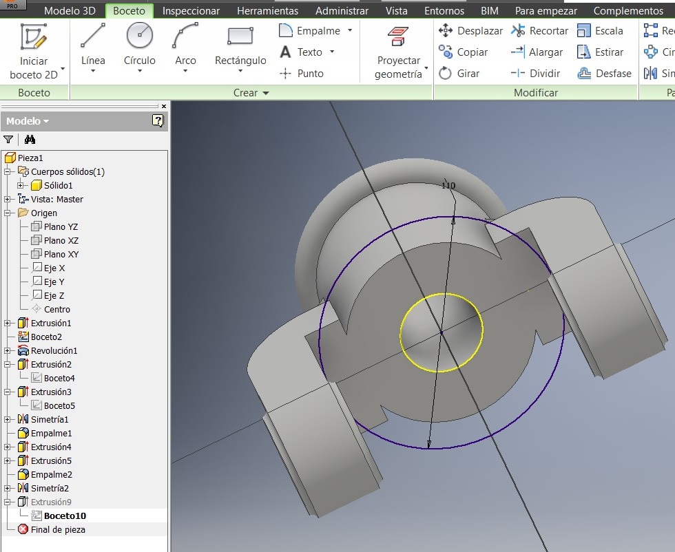
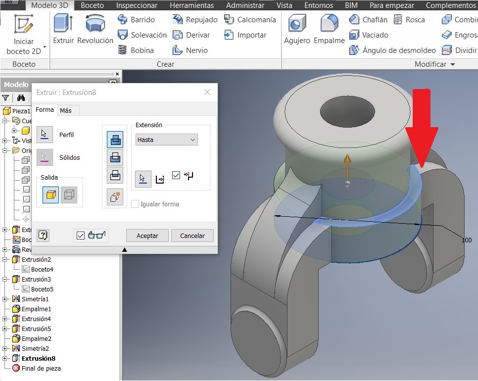
After that I drew another 110 mm circumference to strengthen the piece.
A new sketch on the lateral guide. A 27mm circumference
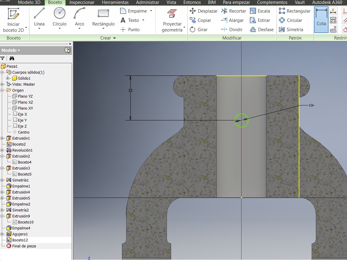
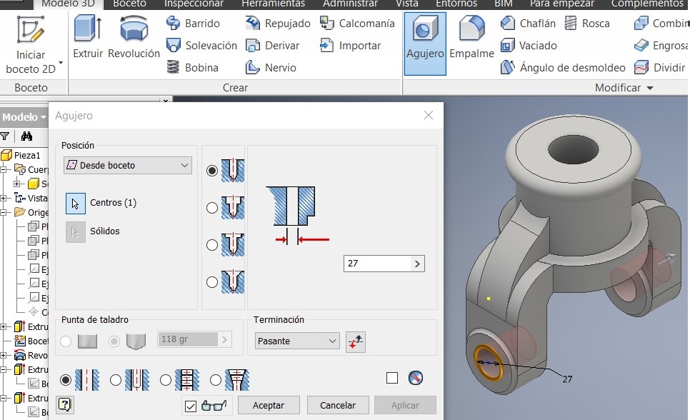
I used the Hole command to project a hole. Again I used the YZ plan
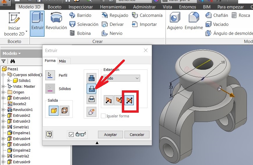
Press F7 to see the imaginary cut and draw a 10 mm circumference. Extrude it using the cut option.
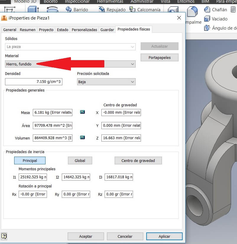
To apply the material features, go to Properties, physical properties, and use the iron. Remember that the software uses a color for every materia.
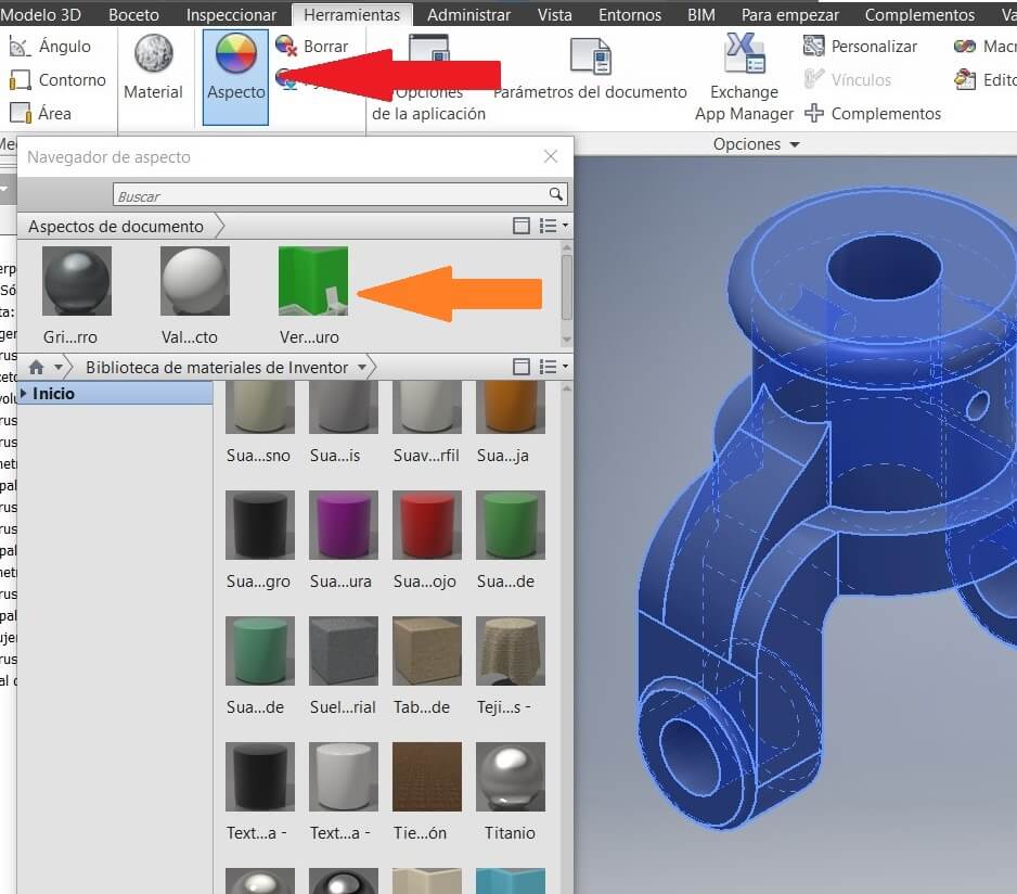
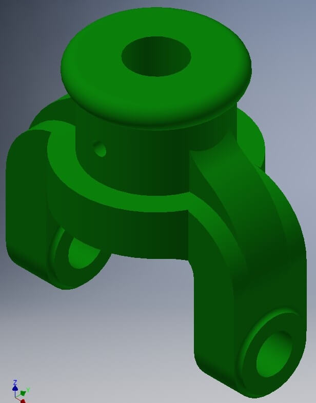
To see the assembly you have to add a color to each solid, to improove the assembly.
Go to Toolbar, clic on Aspect and see the color palette. Choose one and drag to the solid.
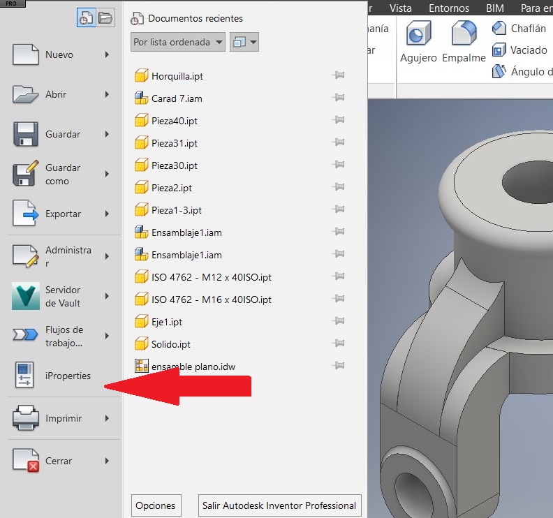
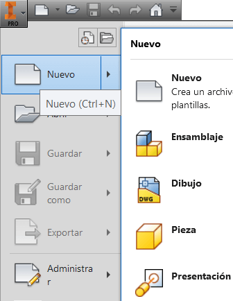
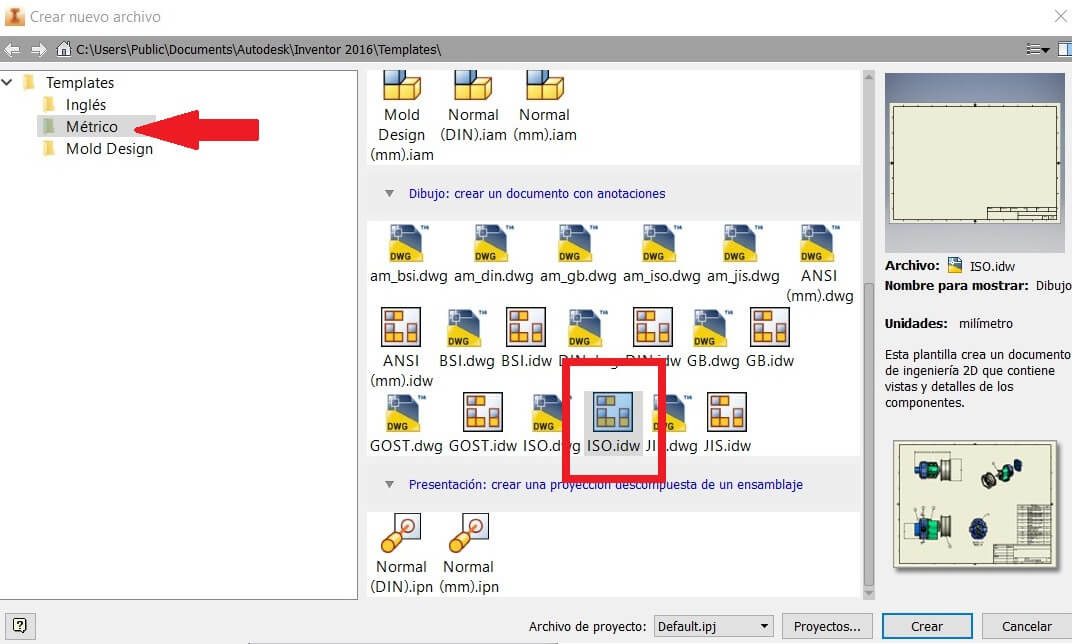
After saving the job, I created a sheet for plans. I used a mm ISO.idw
You can use the Base command to get the saved solid.
Note: Save all the components in a same folder.
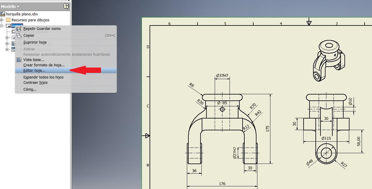
On the browser right clic the Sheet, and then click on Edit.
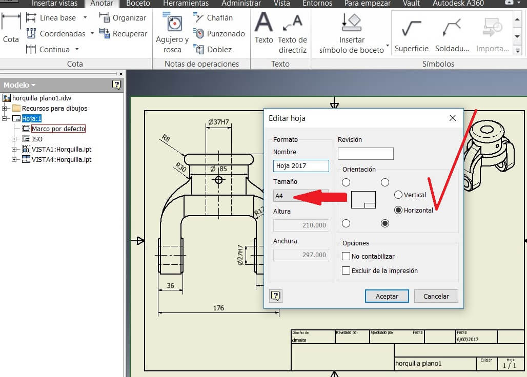
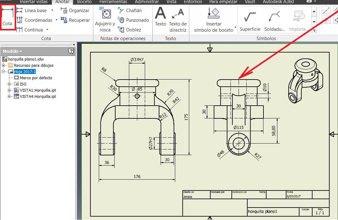
I chose the A4 and a horizontal position to add the views I needed. Then using the toolbar Limits I showed the measures.
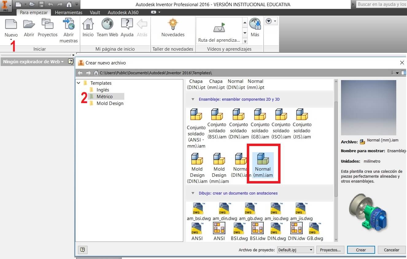
Create a new file called Normal (mm).iam
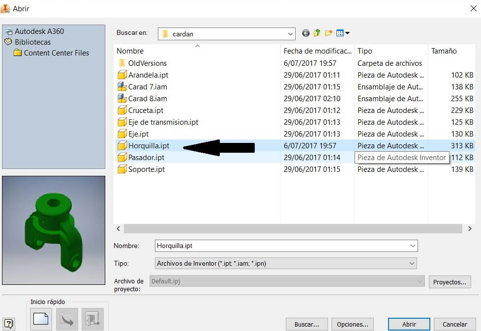
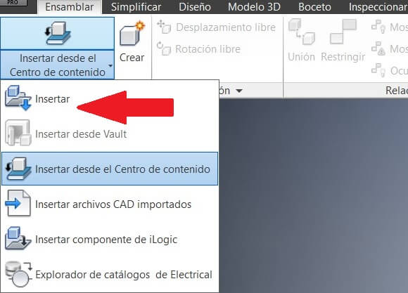
Click on Insert objects
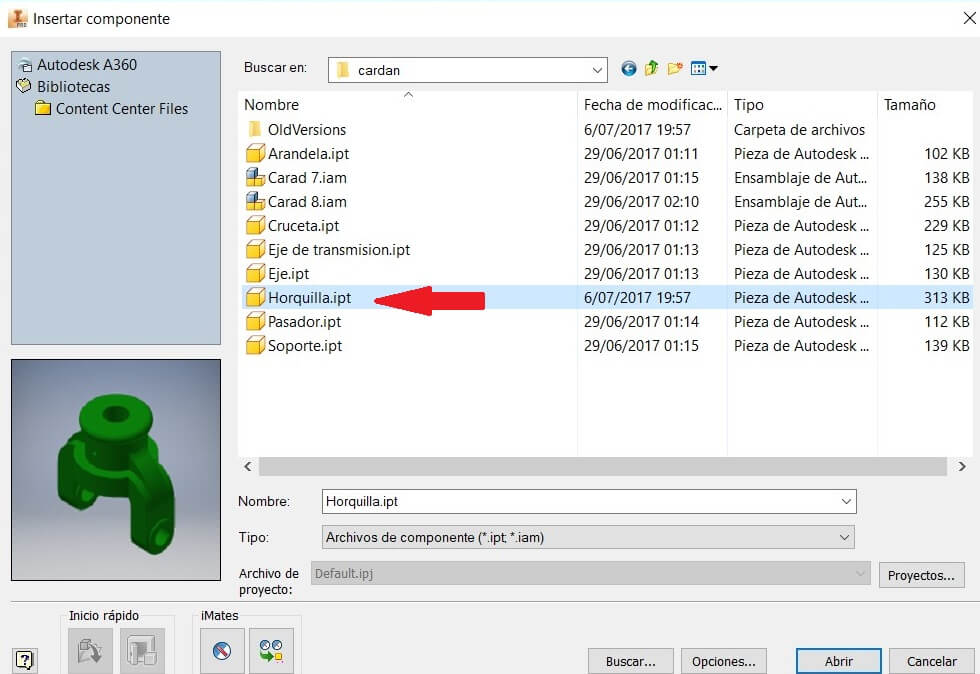
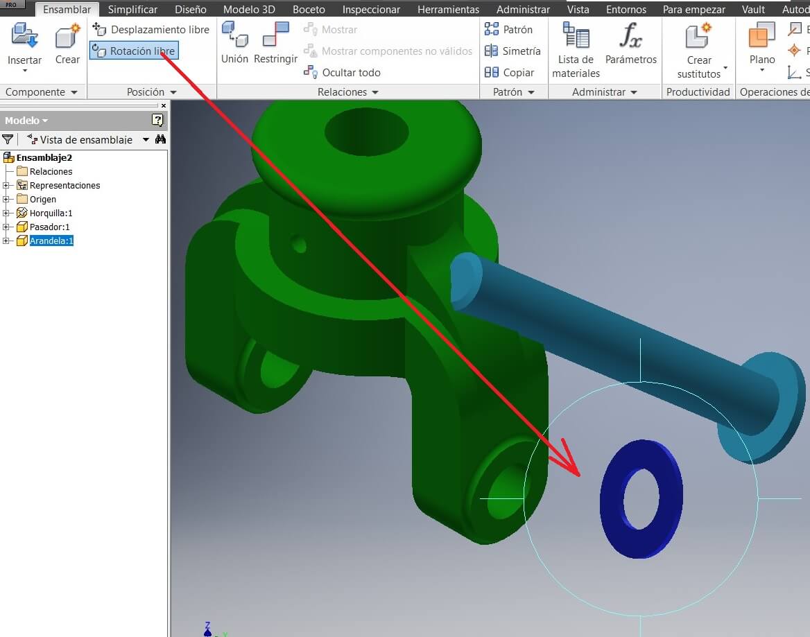
Select the folder and the components for the assembly. Place into the workspace the pieces and using the command Free rotation, assembly
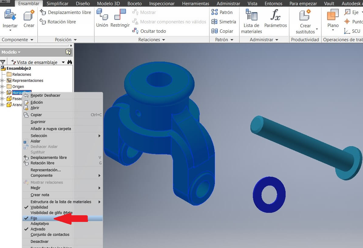
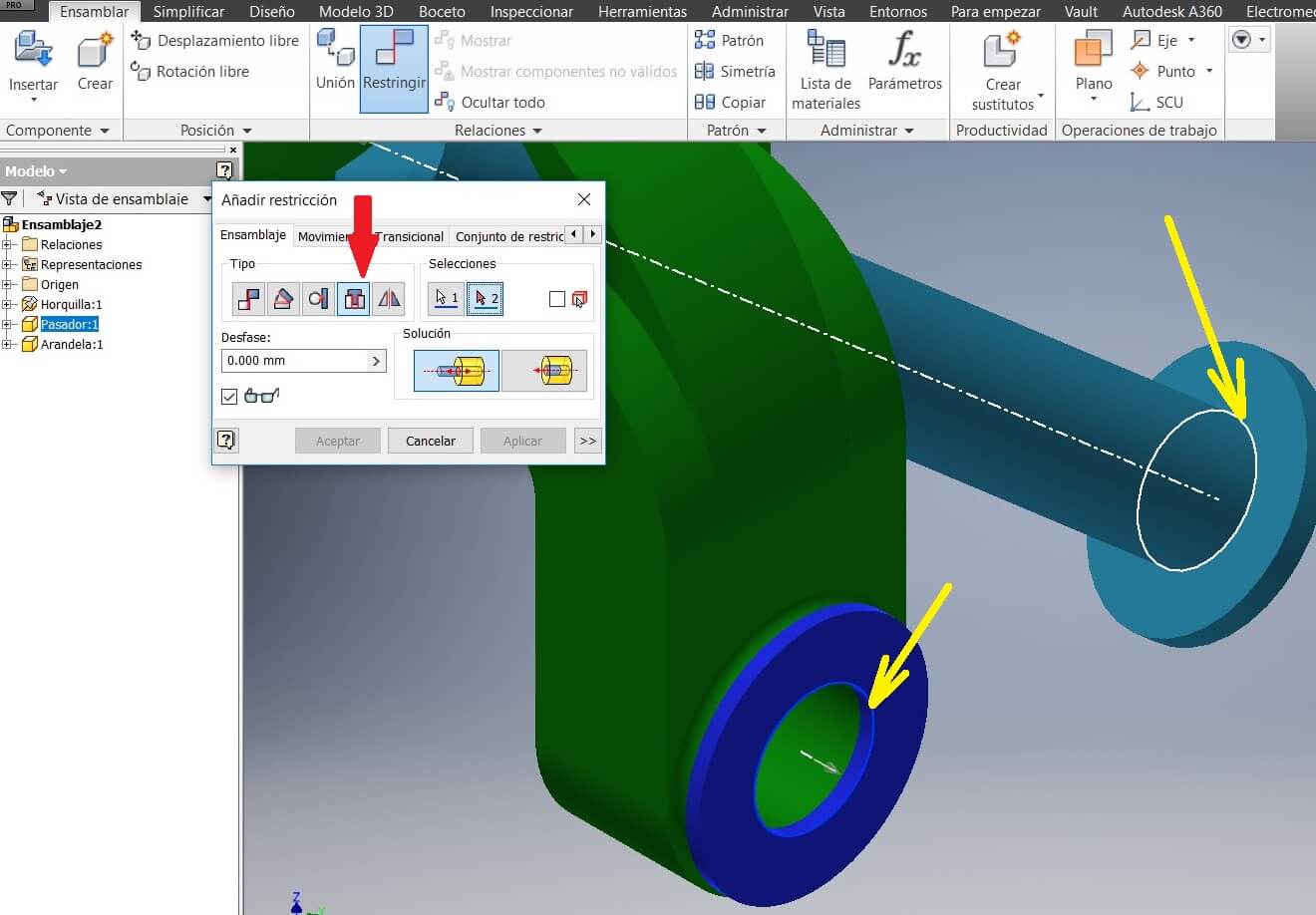
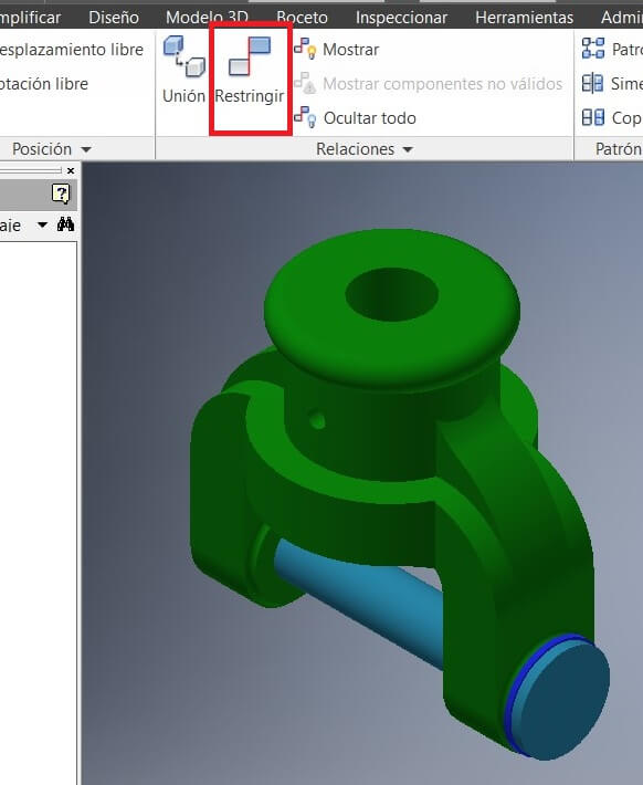
Fix a piece to avoid its movement and using the command Constrains start assembying
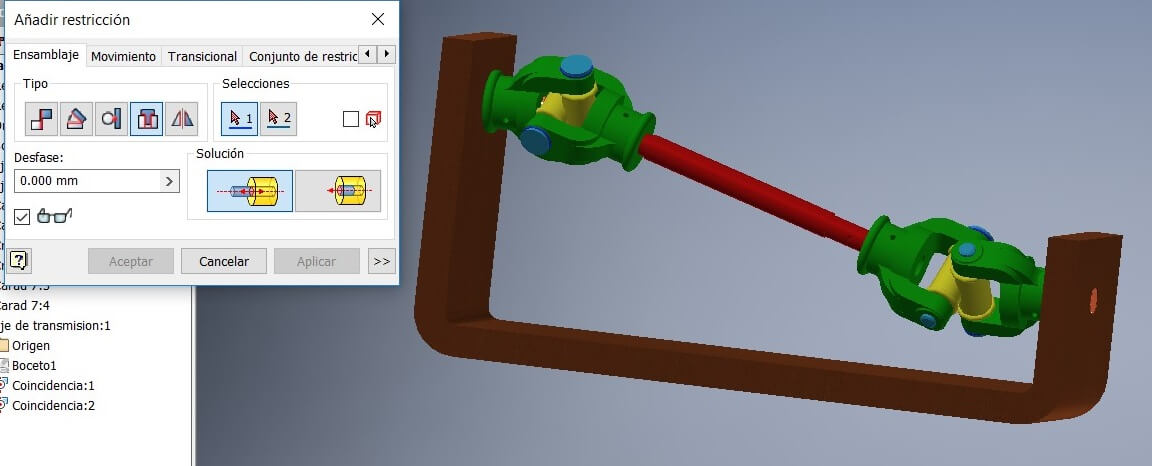
Then we have the partial assembly. Save and repeat to assembly the other pieces.
It wont let you open files made on previous versions.
Here you can find the files