


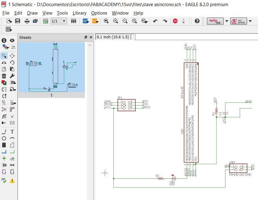
Design and milling of the electronic boards
Program more than 2 components
Show the programming of the serial communication
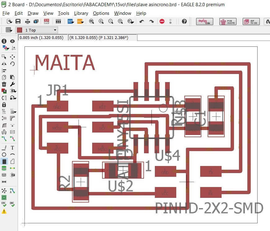 Routing for machining with the milling machine
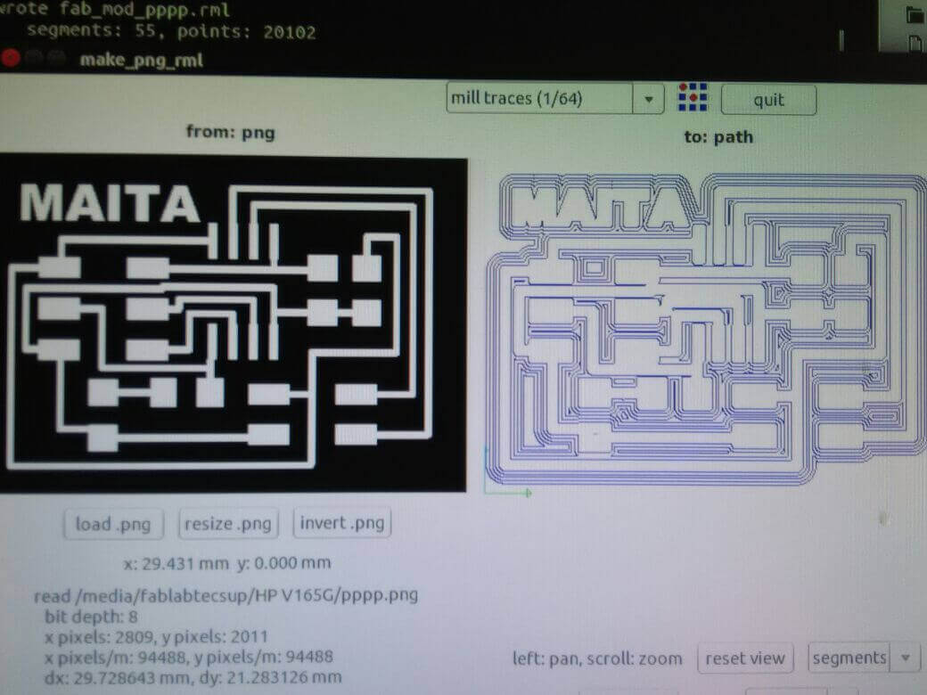
 Procedure for machining the electronic board with the roland milling machine
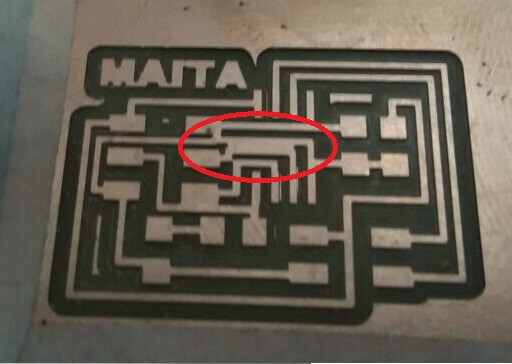
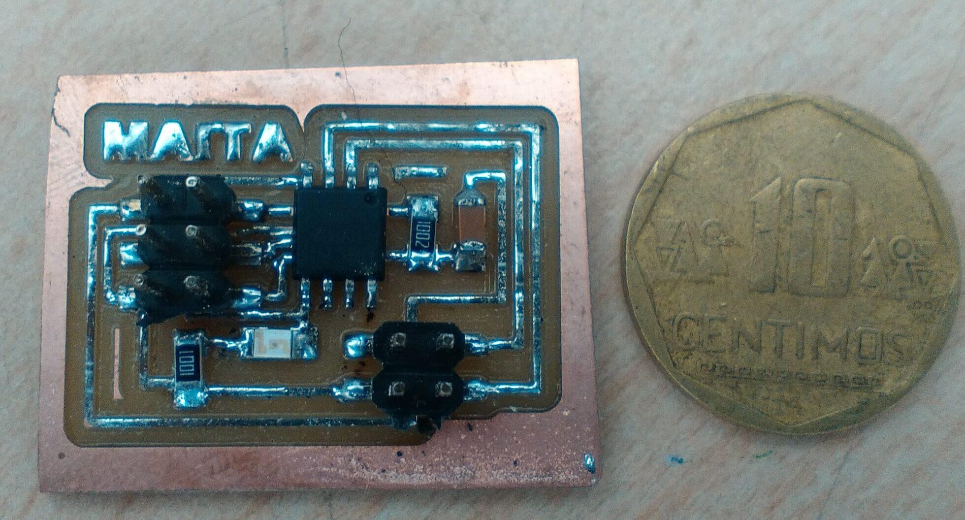
Presentation of the board after the milling
Procedure for machining the electronic board with the roland milling machine
Presentation of the board after the milling
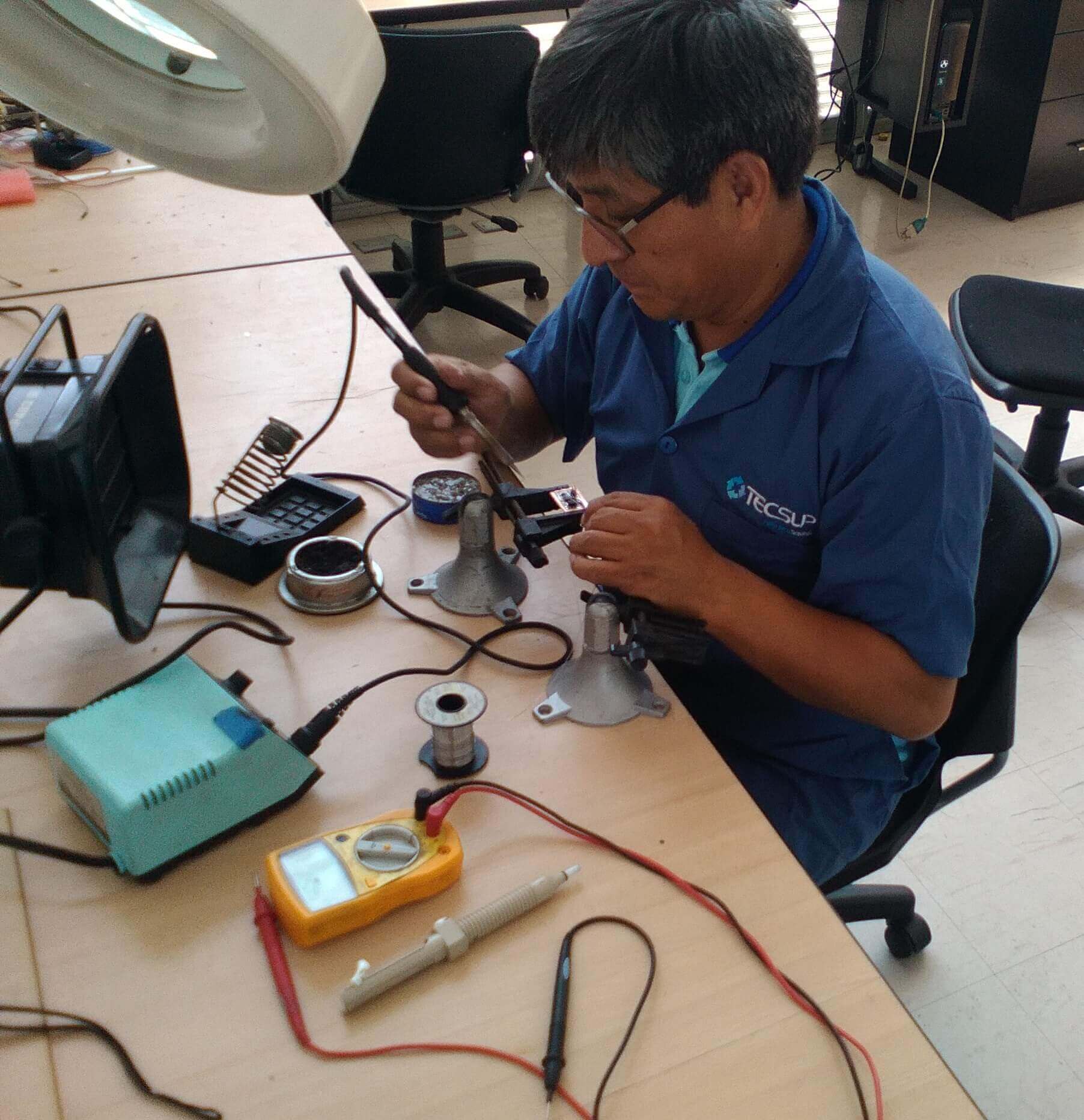
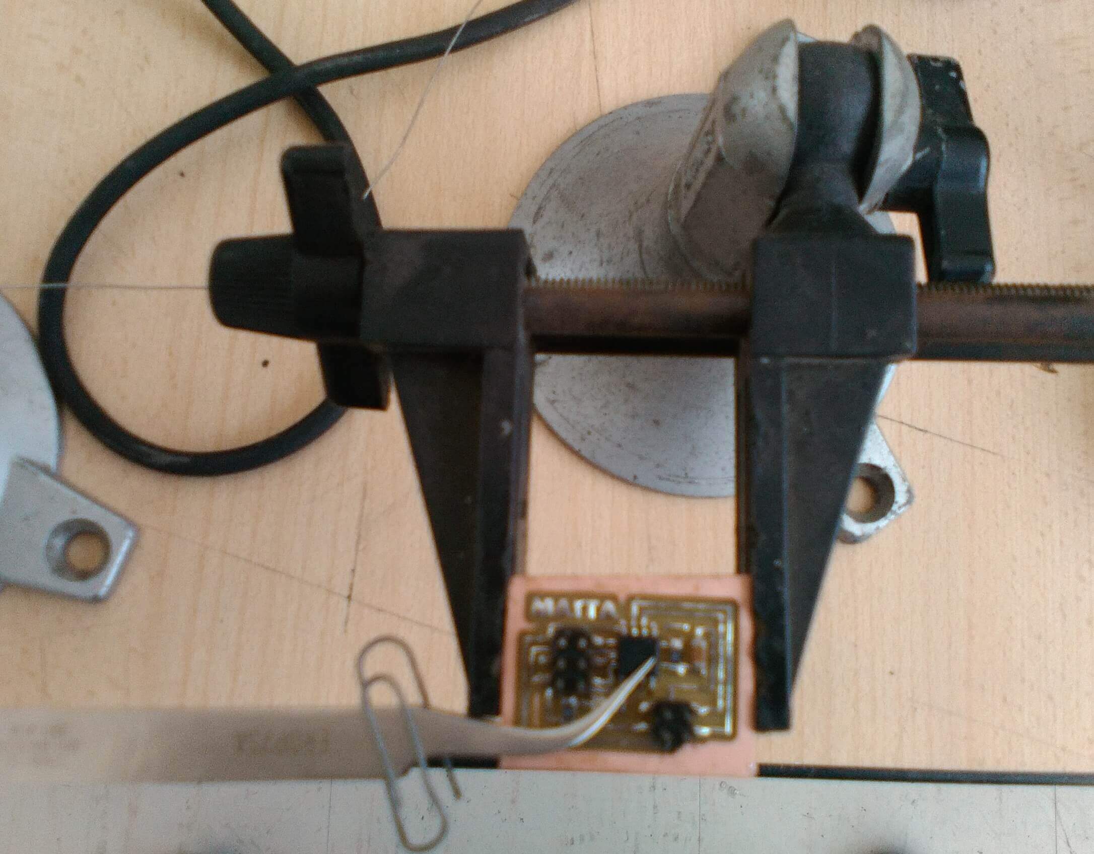
 Welding the components of the electronic board
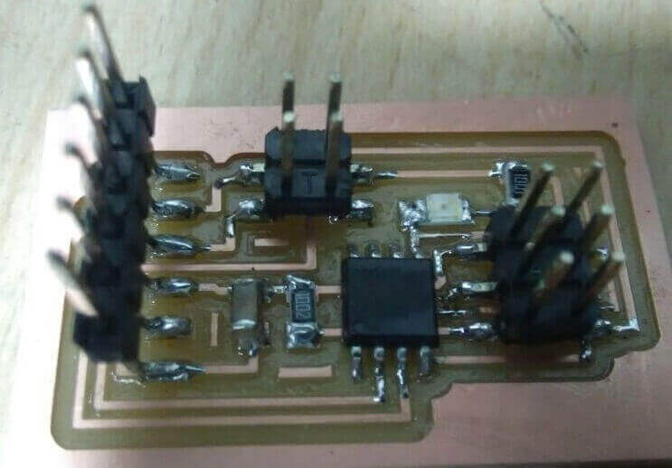
 Slave: Final presentation of the communication card
 Master Presentation of the communication card
 Final test of operation
 Program
        #include
        #include
        #include
        #include
        #define output(directions,pin) (directions |= pin) // set port direction for output
        #define input(directions,pin) (directions &= (~pin)) // set port direction for input
        #define set(port,pin) (port |= pin) // set port pin
        #define clear(port,pin) (port &= (~pin)) // clear port pin
        #define pin_test(pins,pin) (pins & pin) // test for port pin
        #define bit_test(byte,bit) (byte & (1 << bit)) // test for bit set
        #define bit_delay_time 100 // bit delay for 9600 with overhead
        #define bit_delay() _delay_us(bit_delay_time) // RS232 bit delay
        #define half_bit_delay() _delay_us(bit_delay_time/2) // RS232 half bit delay
        #define led_delay() _delay_ms(100) // LED flash delay

        #define led_port PORTB
        #define led_direction DDRB
        #define led_pin (1 << PB0)

        #define serial_port PORTB
        #define serial_direction DDRB
        #define serial_pins PINB
        #define serial_pin_in (1 << PB3)
        #define serial_pin_out (1 << PB4)

        #define node_id '0' ( Importante el Cambo a 0, 1 o 2)

        void get_char(volatile unsigned char *pins, unsigned char pin, char *rxbyte) {
        //
        // read character into rxbyte on pins pin
        //    assumes line driver (inverts bits)
        //
        *rxbyte = 0;
        while (pin_test(*pins,pin))
        //
        // wait for start bit
        //
        ;
        //
        // delay to middle of first data bit
        //
        half_bit_delay();
        bit_delay();
        //
        // unrolled loop to read data bits
        //
        if pin_test(*pins,pin)
        *rxbyte |= (1 << 0);
        else
        *rxbyte |= (0 << 0);
        bit_delay();
        if pin_test(*pins,pin)
        *rxbyte |= (1 << 1);
        else
        *rxbyte |= (0 << 1);
        bit_delay();
        if pin_test(*pins,pin)
        *rxbyte |= (1 << 2);
        else
        *rxbyte |= (0 << 2);
        bit_delay();
        if pin_test(*pins,pin)
        *rxbyte |= (1 << 3);
        else
        *rxbyte |= (0 << 3);
        bit_delay();
        if pin_test(*pins,pin)
        *rxbyte |= (1 << 4);
        else
        *rxbyte |= (0 << 4);
        bit_delay();
        if pin_test(*pins,pin)
        *rxbyte |= (1 << 5);
        else
        *rxbyte |= (0 << 5);
        bit_delay();
        if pin_test(*pins,pin)
        *rxbyte |= (1 << 6);
        else
        *rxbyte |= (0 << 6);
        bit_delay();
        if pin_test(*pins,pin)
        *rxbyte |= (1 << 7);
        else
        *rxbyte |= (0 << 7);
        //
        // wait for stop bit
        //
        bit_delay();
        half_bit_delay();
      }

      void put_char(volatile unsigned char *port, unsigned char pin, char txchar) {
      //
      // send character in txchar on port pin
      //    assumes line driver (inverts bits)
      //
      // start bit
      //
      clear(*port,pin);
      bit_delay();
      //
      // unrolled loop to write data bits
      //
      if bit_test(txchar,0)
      set(*port,pin);
      else
      clear(*port,pin);
      bit_delay();
      if bit_test(txchar,1)
      set(*port,pin);
      else
      clear(*port,pin);
      bit_delay();
      if bit_test(txchar,2)
      set(*port,pin);
      else
      clear(*port,pin);
      bit_delay();
      if bit_test(txchar,3)
      set(*port,pin);
      else
      clear(*port,pin);
      bit_delay();
      if bit_test(txchar,4)
      set(*port,pin);
      else
      clear(*port,pin);
      bit_delay();
      if bit_test(txchar,5)
      set(*port,pin);
      else
      clear(*port,pin);
      bit_delay();
      if bit_test(txchar,6)
      set(*port,pin);
      else
      clear(*port,pin);
      bit_delay();
      if bit_test(txchar,7)
      set(*port,pin);
      else
      clear(*port,pin);
      bit_delay();
      //
      // stop bit
      //
      set(*port,pin);
      bit_delay();
      //
      // char delay
      //
      bit_delay();
    }

    void put_string(volatile unsigned char *port, unsigned char pin, PGM_P str) {
    //
    // send character in txchar on port pin
    //    assumes line driver (inverts bits)
    //
    static char chr;
    static int index;
    index = 0;
    do {
    chr = pgm_read_byte(&(str[index]));
    put_char(&serial_port, serial_pin_out, chr);
    ++index;
  } while (chr != 0);
}

void flash() {
//
// LED flash delay
//
clear(led_port, led_pin);
led_delay();
set(led_port, led_pin);
}

int main(void) {
//
// main
//
static char chr;
//
// set clock divider to /1
//
CLKPR = (1 << CLKPCE);
CLKPR = (0 << CLKPS3) | (0 << CLKPS2) | (0 << CLKPS1) | (0 << CLKPS0);
//
// initialize output pins
//
set(serial_port, serial_pin_out);
input(serial_direction, serial_pin_out);
set(led_port, led_pin);
output(led_direction, led_pin);
//
// main loop
//
while (1) {
get_char(&serial_pins, serial_pin_in, &chr);
flash();
if (chr == node_id) {
output(serial_direction, serial_pin_out);
static const char message[] PROGMEM = "node ";
put_string(&serial_port, serial_pin_out, (PGM_P) message);
put_char(&serial_port, serial_pin_out, chr);
put_char(&serial_port, serial_pin_out, 10); // new line
led_delay();
flash();
input(serial_direction, serial_pin_out);
}
}
}
Programming Files Here
Why did I choose this type of protocol?
I decided to use the I2C communication protocol because I found more information about it and I found it very easy to understand.
The I2C communication only needs a master and I can have an infinity of slaves (in theory), just give them a name and program the order, also their connection is very simple are only two cables one where the data goes and the other the signal Clock, which facilitates communication.
In contrast, in a Bluetooth communication, two bluetooth modules had to be connected for the master and the other for the slave. Since the bluetooth communication is point to point.