


Add an output device to a microcontroller board you've designed and program it to do something
*Measure something: Add a sensor to a microcontroller board that you have designed and read
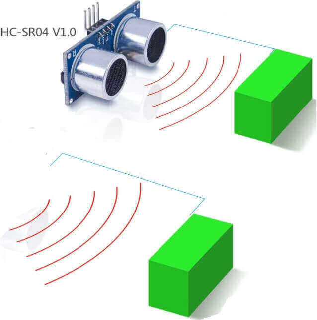
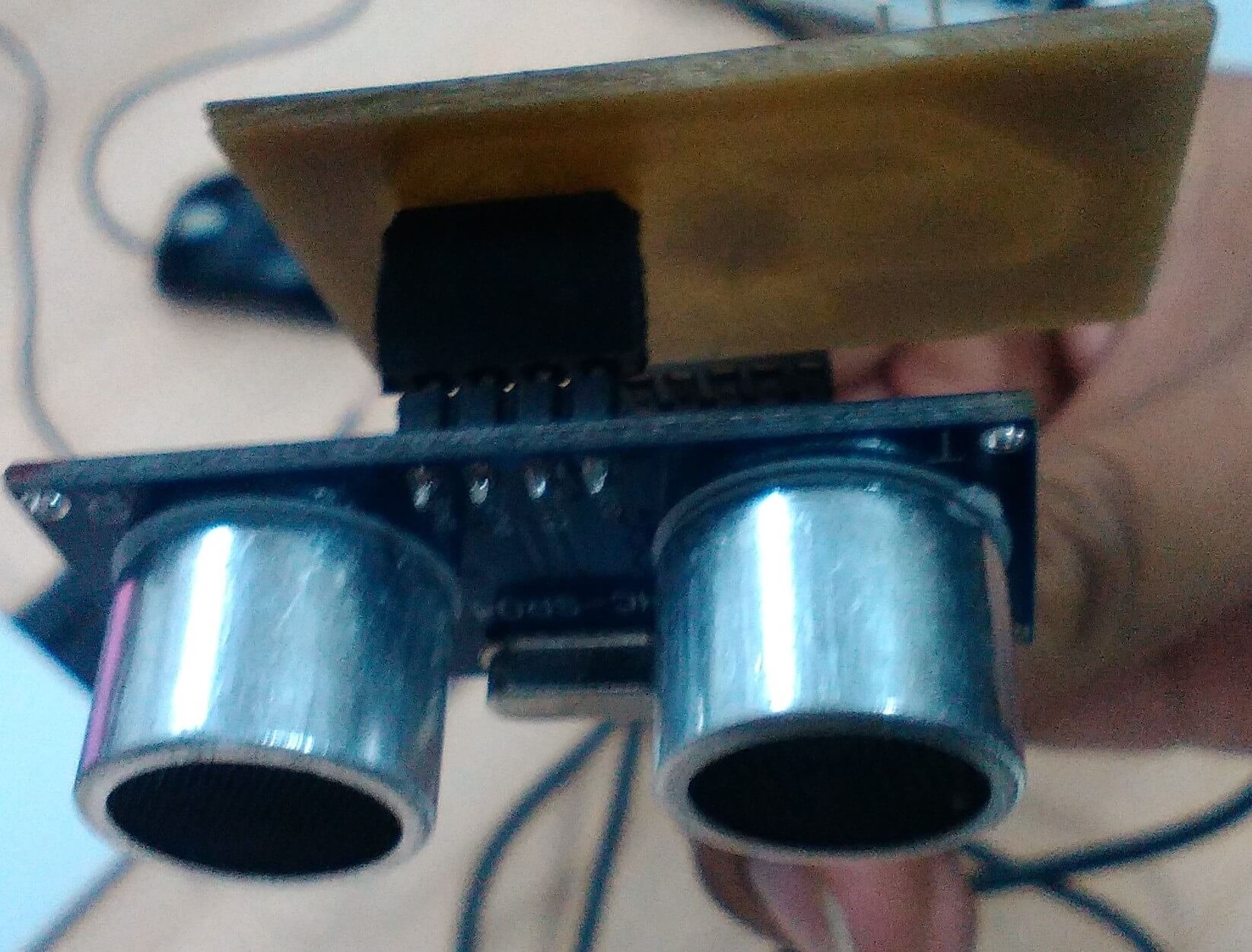
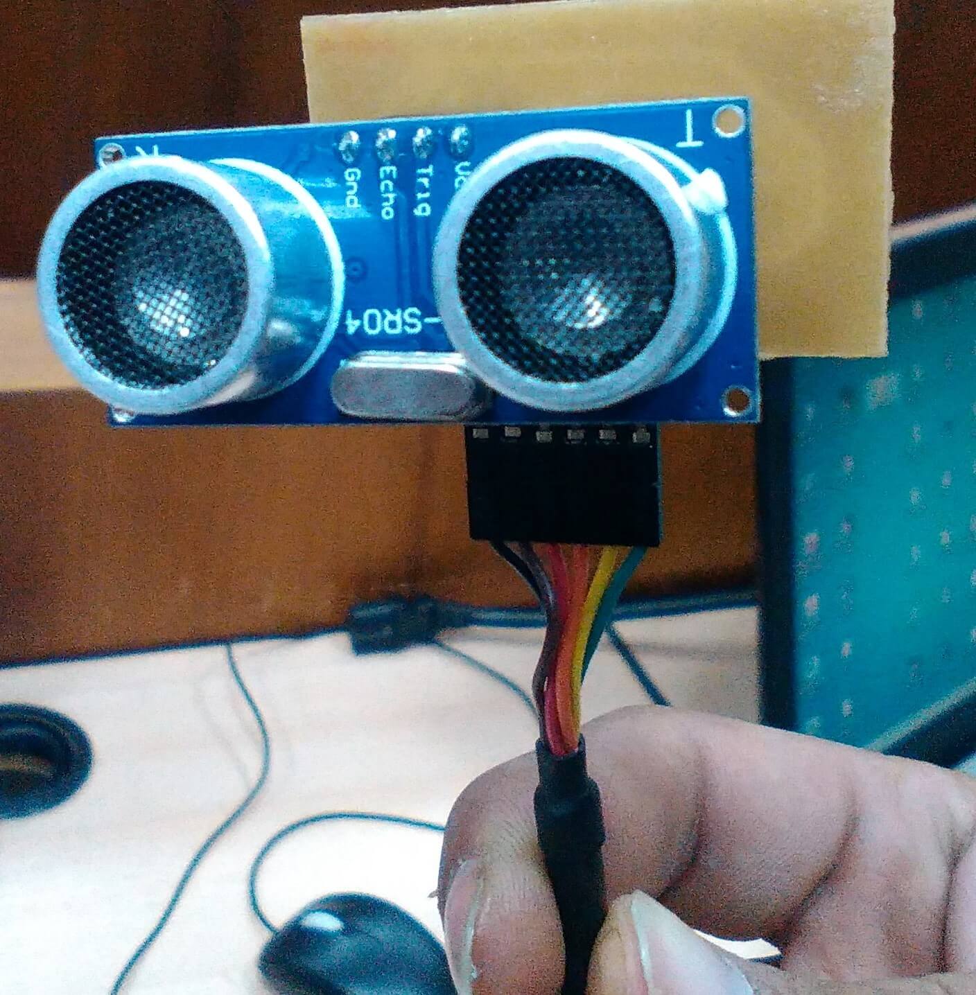
- Selected to make an ultrasonic sensor circuit board (HC-SR04) "Motion detector sensor" as input device
- A motion detector is a device that detects moving objects, especially people
- A motion detector is often integrated as a component of a system that automatically performs a task or alerts a user about movement in an area
There are 5 tecnologies to detect movement:
PIR (Infra red)
Microwaves
Ultrasonic *
Tomografic movement detector
Videocamera software
Here I use the ultrasonic sensor
The amount of acoustic energy reflected by the obstacle depends largely on the structure of its surface. To obtain a highly diffuse reflection of the obstacle, the size of the irregularities on the reflecting surface should be comparable to the wavelength of the incident ultrasound wave.
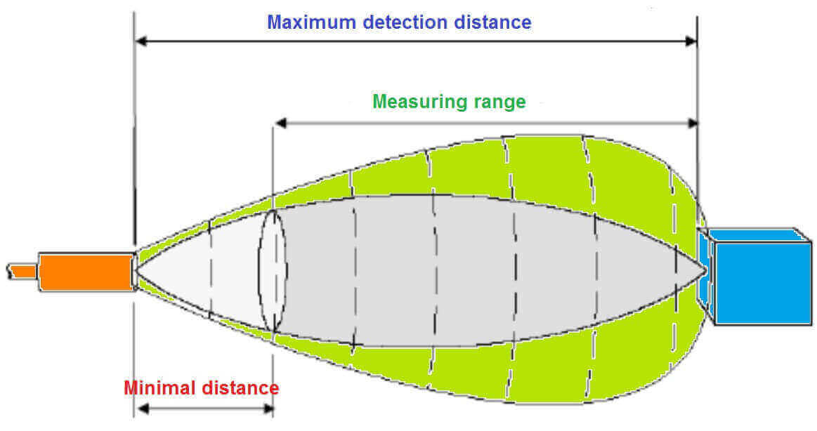
Environmental factors have a great impact on the measurements:
Ultrasound waves are moved by a material medium that is air. The density of the air depends on the temperature, influencing this factor on the speed of propagation of the wave
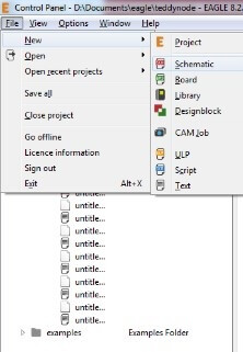
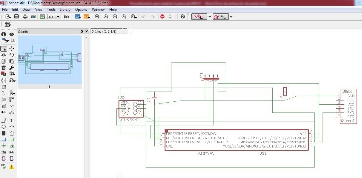
Active the program “Eagle” and design a Schematic. Then, Click on the "Add" option where you find the "fab" library
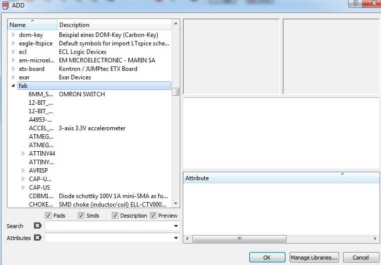
After, look for the components to make our plate
- AVRISPRSMD
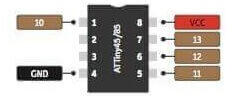
- ATinny45
- FTDI-SMD-HEADER
- R-EU_R3216 (R-EU_)
- CAP-UNPOLARIZED FAB (CAP-UNPOLARIZED)
- JP4E (for ultrasonic sensor pins)
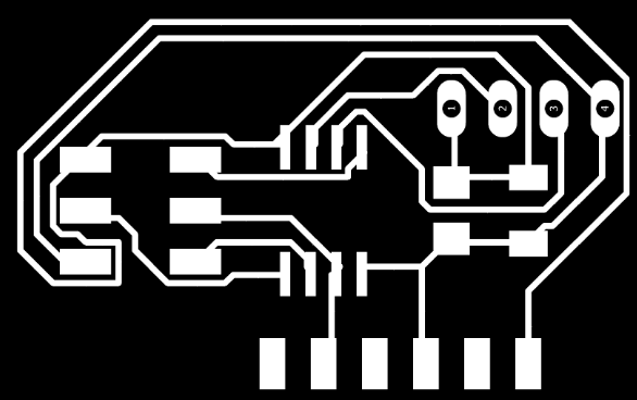
When I have all the components I I made necessary connections on the Schematic sheet. Then again click on the "generate board" option to make the design of my electronic board.

Use a route option that performs the tracks, but before I had to put some parameters like that is the layer (TOP), size (12) and Drill (13.779)
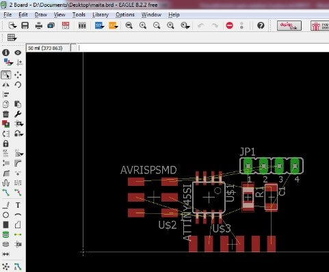
Then, connect the pins where appropriate to have my design, with its routing
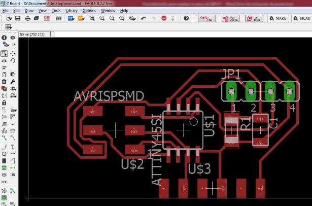
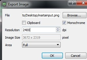
Then generate an image of my electronic design I had to select in "layer setting" and deselect everything I accept "TOP" and Pads, finally go to export as image.
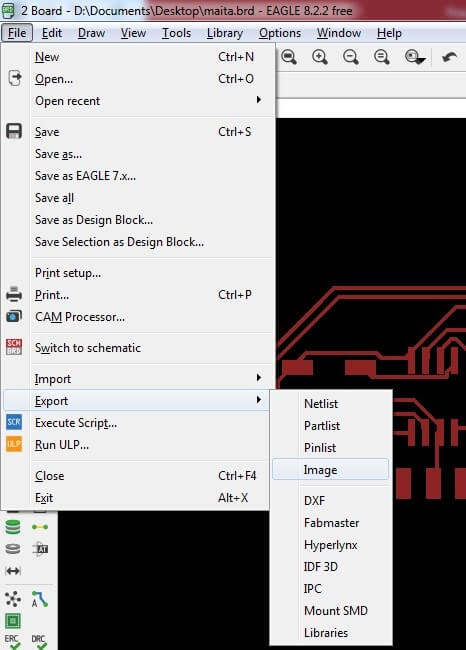
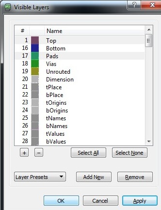
I gave him a name and address where we want to save it with the following parameters
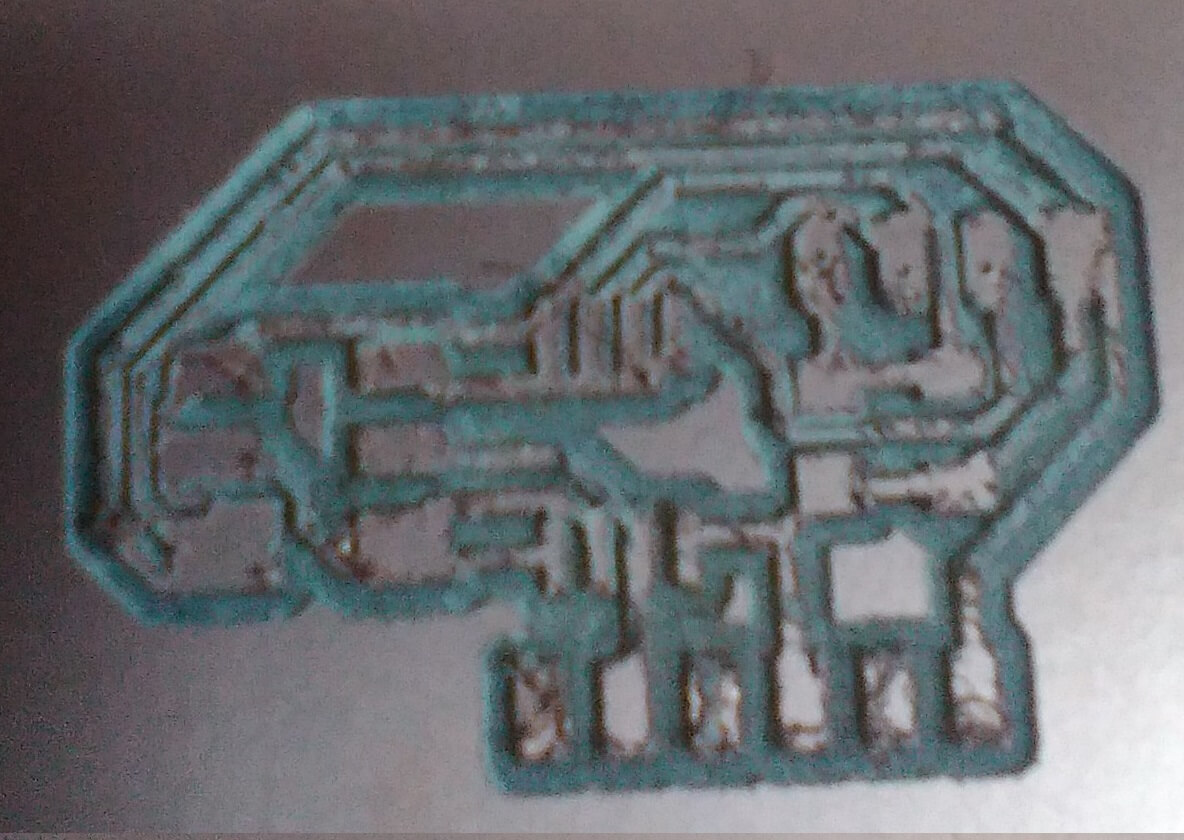
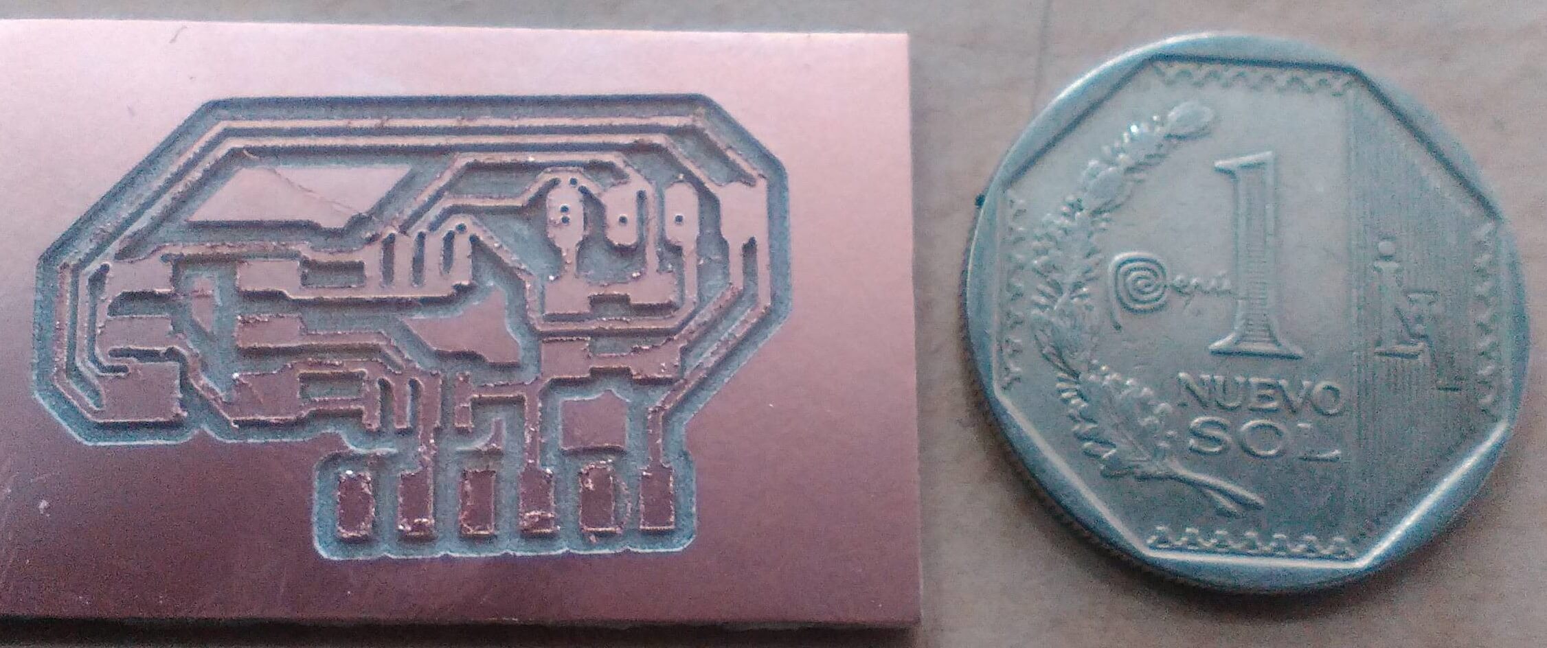
Make my own design of my electronic card Then performs the milling with a 1/64 "diameter cutter on the electronic card in the milling machine Roland" Model mMDX-20 "
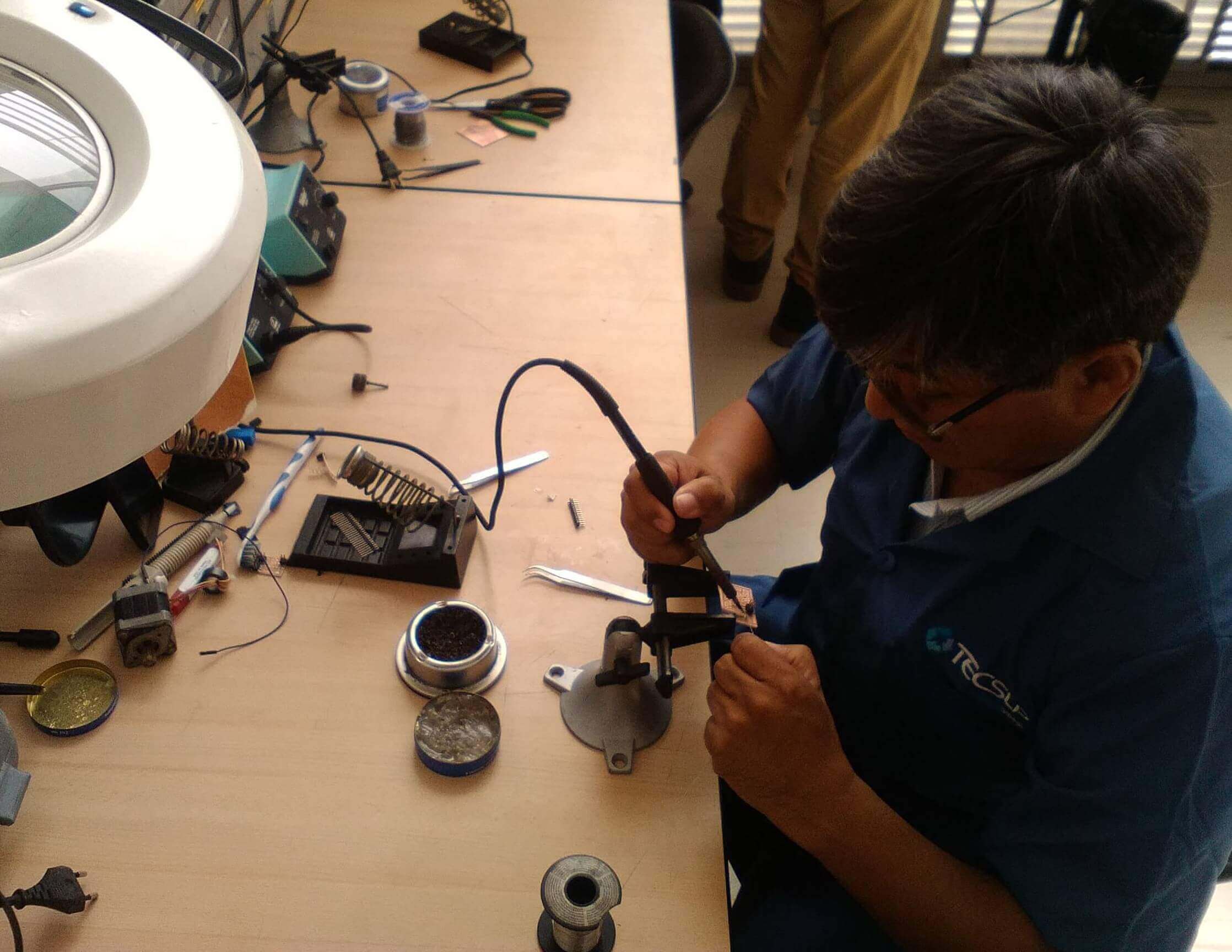
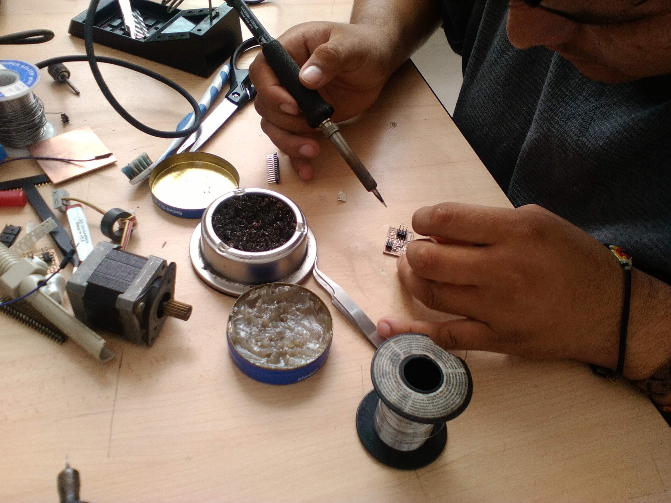
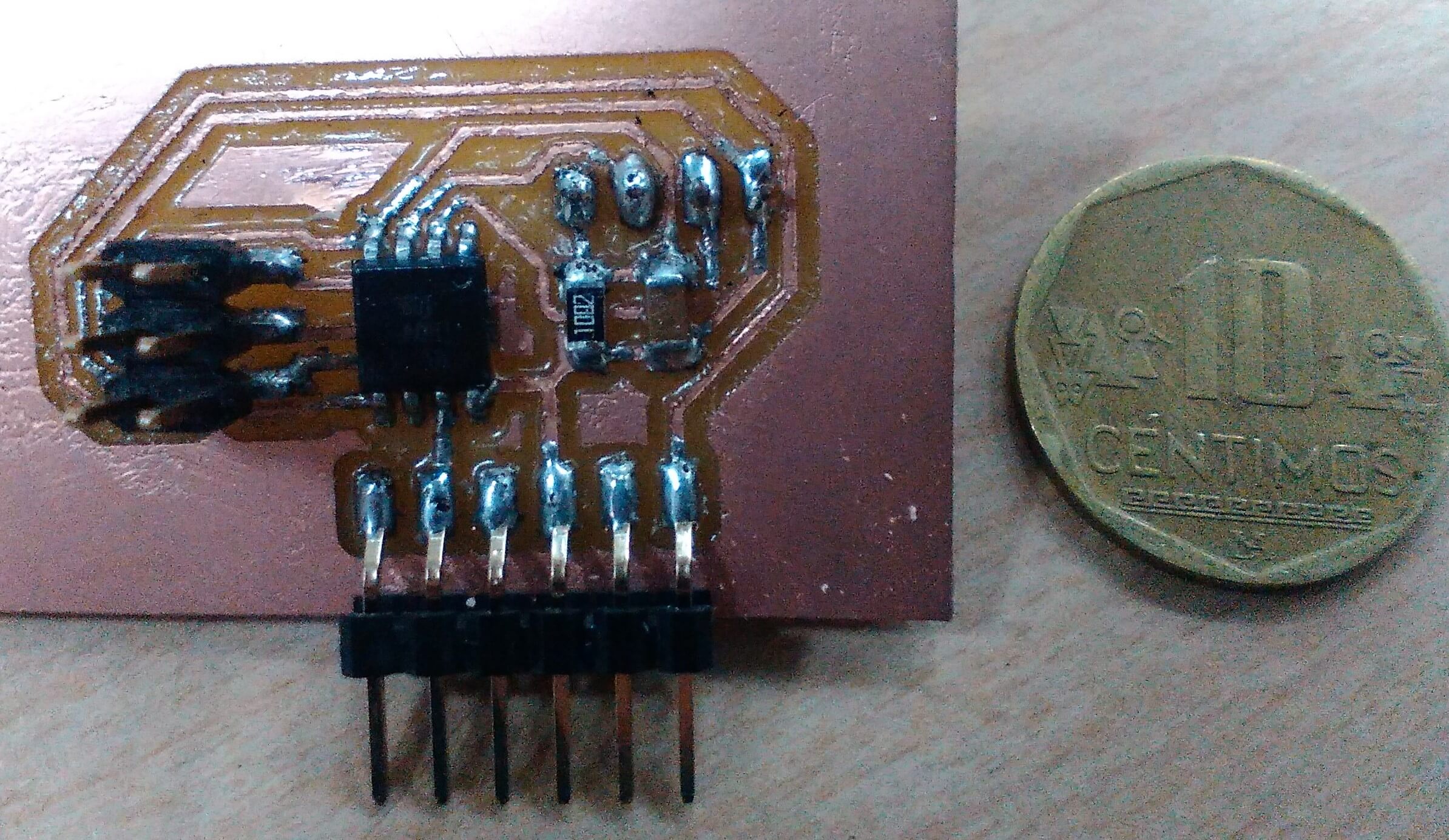
I soldered the components on the board
Make the AVR connection to check if there is a short on my electronic card.
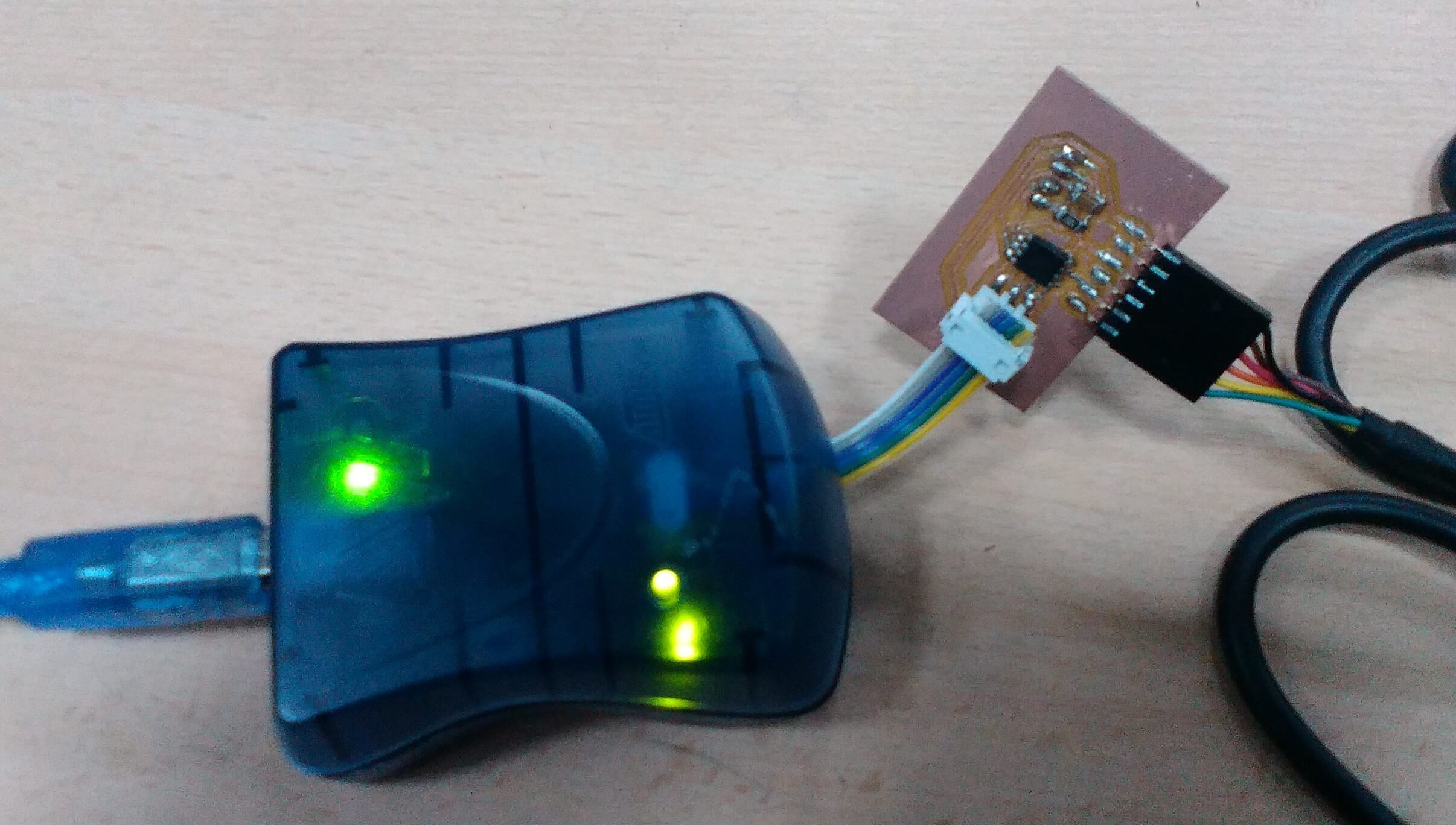
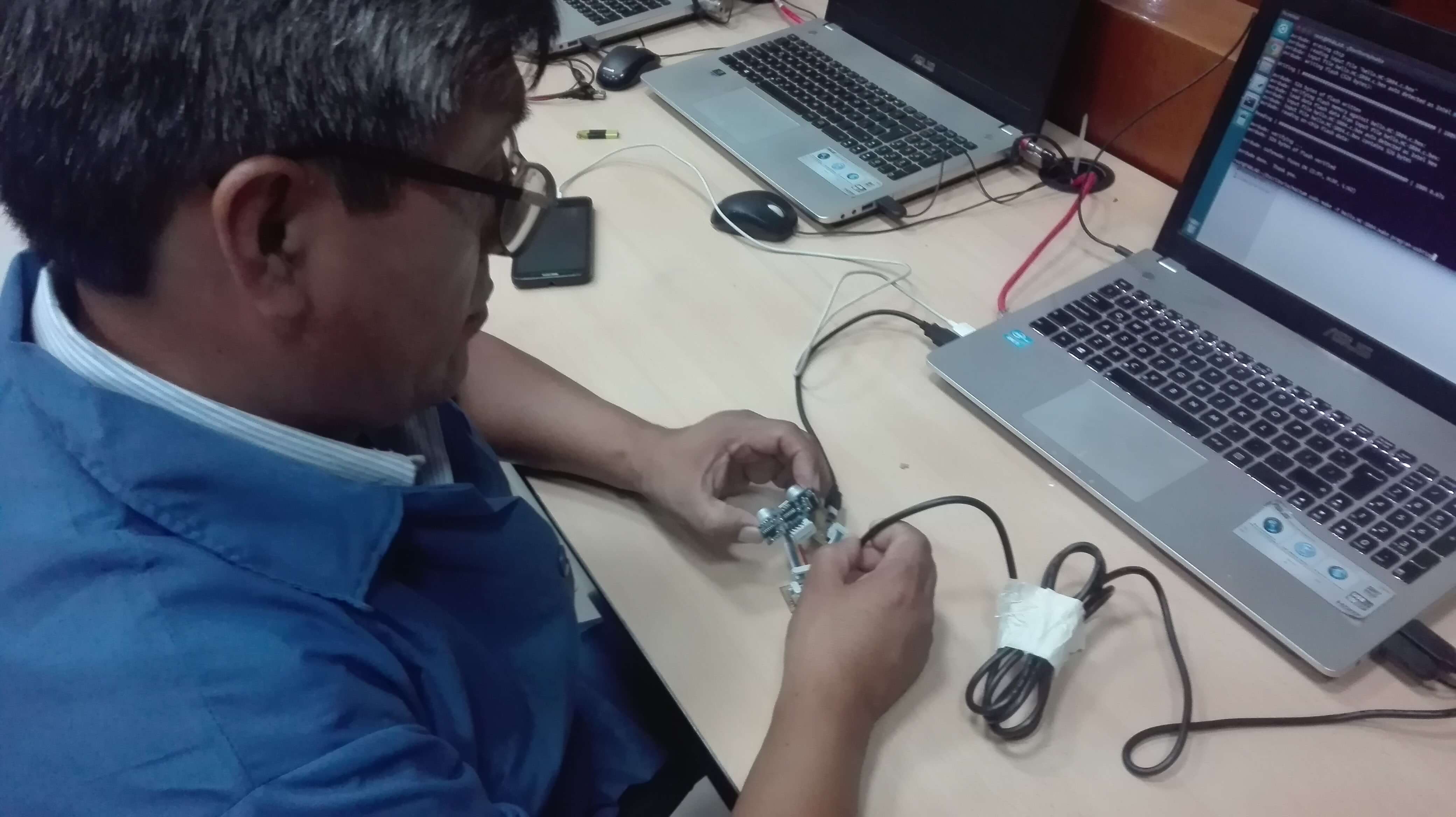
Then I programmed the Attiny44 and the ultrasonic sensor using Ubuntu's terminal
Then connect the ultrasonic sensors
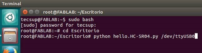
Perform the programming of the Attiny44 microcontroller and the distance sensor Use ubuntu software, run .py to perform programming
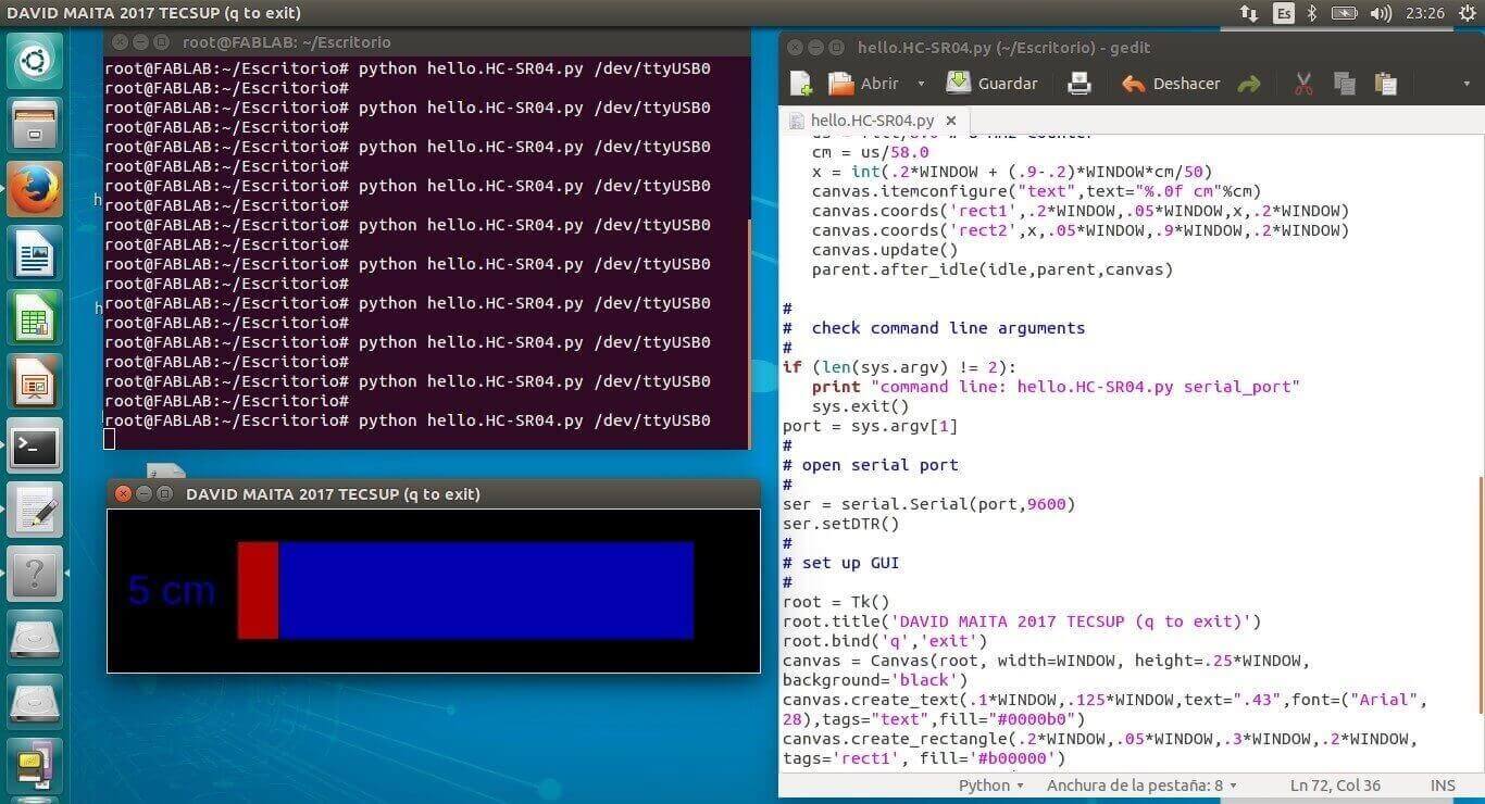
Here is the code
#
# hello.HC-SR04.py
#
# HC-SR04 sonar hello-world
# hello.HC-SR04.py serial_port
#
# Neil Gershenfeld 11/15/15
# (c) Massachusetts Institute of Technology 2015
#
# This work may be reproduced, modified, distributed,
# performed, and displayed for any purpose. Copyright is
# retained and must be preserved. The work is provided
# as is; no warranty is provided, and users accept all
# liability.
#
from Tkinter import *
import serial
WINDOW = 600 # window size
filt = 0
eps = 0.1
def idle(parent,canvas):
global filt,eps
#
# idle routine
#
byte2 = 0
byte3 = 0
byte4 = 0
ser.flush()
while 1:
#
# find framing
#
byte1 = byte2
byte2 = byte3
byte3 = byte4
byte4 = ord(ser.read())
if ((byte1 == 1) & (byte2 == 2) & (byte3 == 3) & (byte4 == 4)):
break
low = ord(ser.read())
high = ord(ser.read())
value = (256*high + low)
filt = (1-eps)*filt+eps*value
us = filt/8.0 # 8 MHz counter
cm = us/58.0
x = int(.2*WINDOW + (.9-.2)*WINDOW*cm/50)
canvas.itemconfigure("text",text="%.0f cm"%cm)
canvas.coords('rect1',.2*WINDOW,.05*WINDOW,x,.2*WINDOW)
canvas.coords('rect2',x,.05*WINDOW,.9*WINDOW,.2*WINDOW)
canvas.update()
parent.after_idle(idle,parent,canvas)
#
# check command line arguments
#
if (len(sys.argv) != 2):
print "command line: hello.HC-SR04.py serial_port"
sys.exit()
port = sys.argv[1]
#
# open serial port
#
ser = serial.Serial(port,9600)
ser.setDTR()
#
# set up GUI
#
root = Tk()
root.title('hello.HC-SR04.py (q to exit)')
root.bind('q','exit')
canvas = Canvas(root, width=WINDOW, height=.25*WINDOW, background='white')
canvas.create_text(.1*WINDOW,.125*WINDOW,text=".33",font=("Helvetica", 24),tags="text",fill="#0000b0")
canvas.create_rectangle(.2*WINDOW,.05*WINDOW,.3*WINDOW,.2*WINDOW, tags='rect1', fill='#b00000')
canvas.create_rectangle(.3*WINDOW,.05*WINDOW,.9*WINDOW,.2*WINDOW, tags='rect2', fill='#0000b0')
canvas.pack()
#
# start idle loop
#
root.after(100,idle,root,canvas)
root.mainloop()
#
# hello.HC-SR04.py
#
# HC-SR04 sonar hello-world
# hello.HC-SR04.py serial_port
#
# Neil Gershenfeld 11/15/15
# (c) Massachusetts Institute of Technology 2015
#
# This work may be reproduced, modified, distributed,
# performed, and displayed for any purpose. Copyright is
# retained and must be preserved. The work is provided
# as is; no warranty is provided, and users accept all
# liability.
#
from Tkinter import *
import serial
WINDOW = 600 # window size
filt = 0
eps = 0.1
def idle(parent,canvas):
global filt,eps
#
# idle routine
#
byte2 = 0
byte3 = 0
byte4 = 0
ser.flush()
while 1:
#
# find framing
#
byte1 = byte2
byte2 = byte3
byte3 = byte4
byte4 = ord(ser.read())
if ((byte1 == 1) & (byte2 == 2) & (byte3 == 3) & (byte4 == 4)):
break
low = ord(ser.read())
high = ord(ser.read())
value = (256*high + low)
filt = (1-eps)*filt+eps*value
us = filt/8.0 # 8 MHz counter
cm = us/58.0
x = int(.2*WINDOW + (.9-.2)*WINDOW*cm/50)
canvas.itemconfigure("text",text="%.0f cm"%cm)
canvas.coords('rect1',.2*WINDOW,.05*WINDOW,x,.2*WINDOW)
canvas.coords('rect2',x,.05*WINDOW,.9*WINDOW,.2*WINDOW)
canvas.update()
parent.after_idle(idle,parent,canvas)
#
# check command line arguments
#
if (len(sys.argv) != 2):
print "command line: hello.HC-SR04.py serial_port"
sys.exit()
port = sys.argv[1]
#
# open serial port
#
ser = serial.Serial(port,9600)
ser.setDTR()
#
# set up GUI
#
root = Tk()
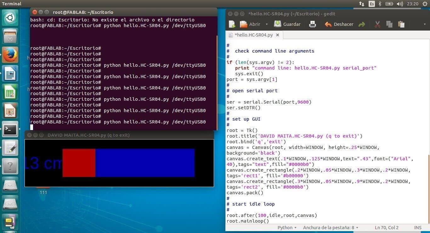
root.title('DAVID MAITA.HC-SR04.py (q to exit)')
root.bind('q','exit')
canvas = Canvas(root, width=WINDOW, height=.25*WINDOW, background='black')
canvas.create_text(.1*WINDOW,.125*WINDOW,text=".43",font=("Arial", 40),tags="text",fill="#0000b0")
canvas.create_rectangle(.2*WINDOW,.05*WINDOW,.3*WINDOW,.2*WINDOW, tags='rect1', fill='#b00000')
canvas.create_rectangle(.3*WINDOW,.05*WINDOW,.9*WINDOW,.2*WINDOW, tags='rect2', fill='#0000b0')
canvas.pack()
#
# start idle loop
#
root.after(100,idle,root,canvas)
root.mainloop()
Calibrating the device
Here you can find the files:
I learned the parameters for milling electronic boards
I applied solder to electronic components
I learned how to program the microcontroller to use a distance sensor
I learned how to read and process an electronic signal