Week 7: Computer Controlled Machining
This week our task was to make something BIG using the CNC machine
I was inspired to make a laptop table using a kerf design for the edges. I found these two students excellent guides for thinking through different designs. Eva Korae and Shelga Hauksdottir
I also found a sample of flexible wood in our Fab Lab: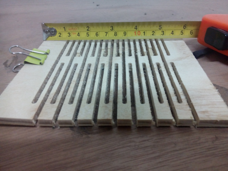
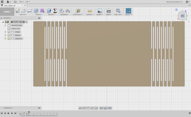
I began drawing a parametric model with Fusion 360. This was straightforward after I figured out how to use the ‘rectangular pattern’ function (to create an array of slots at regular intervals to make the pattern) and ‘mirror’ function (to copy the pattern from the left side to the right side). One of the major design decisions is the height of the material in relation to the width of the kerf pattern. I want the wood to curve down into legs, yet still remain sturdy to support the weight of a laptop. Another of the design questions is whether the legs will be stable (so as not to flip back up). I have a few ideas in mind to work with this: (a) folding under the legs, (b) threading string through the kerf to hold the legs in tension (inspired by Eva Korae), or (c) adding some glue. Ideally I’d like to steer clear of the last option, because I’d like to be able to have a flexible design that allows the legs to fold up and down as required.
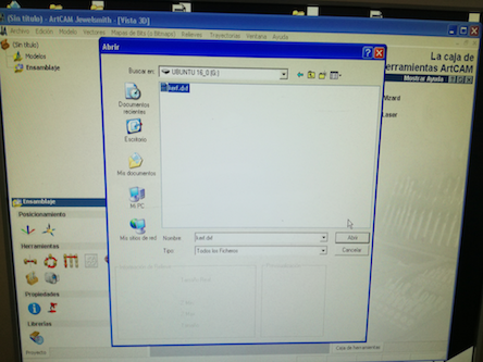
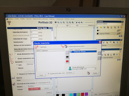
I exported the Fusion model as a .dxf file, which can be read by the CNC Art CAM Jewel Smith software. In the software, the following tool path settings were needed as inputs:
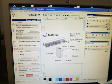
- Depth of cut: in my case, this was the depth of the material (9mm)
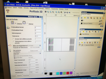
- Width of the tool in use: 6mm
- Vertical trajectory, meaning how deep the tool goes in each pass: 3mm/pass
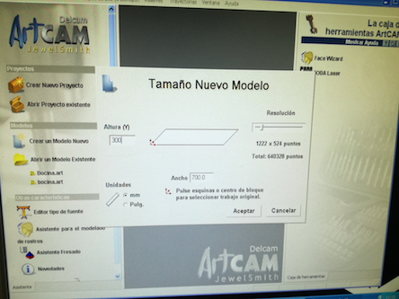
- Dimensions of the material: (700 x 300 mm)
The following pictures show the stages of first loading in the .dxf file into Art CAM, then adding material dimensions, specifications, and toolpath settings into the software
I then saved the trajectories file (G code), and imported it into the Mach3 CNC Controller software.
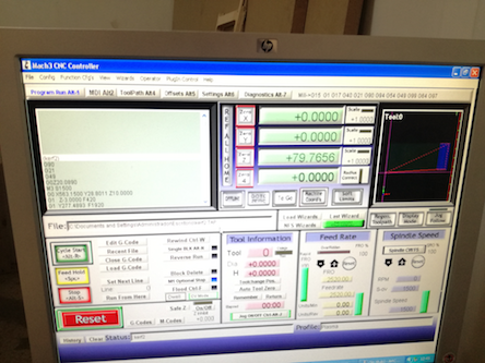
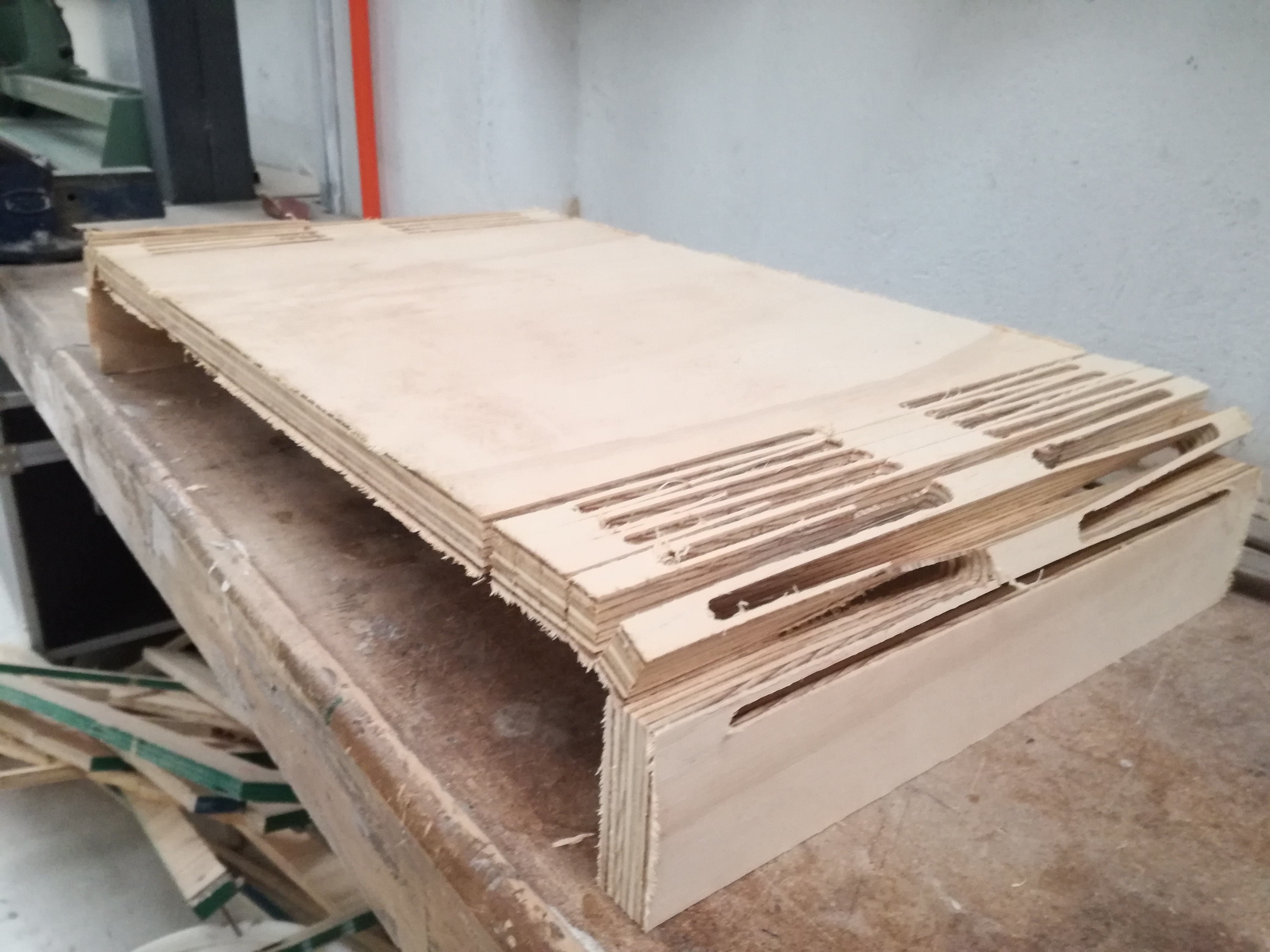
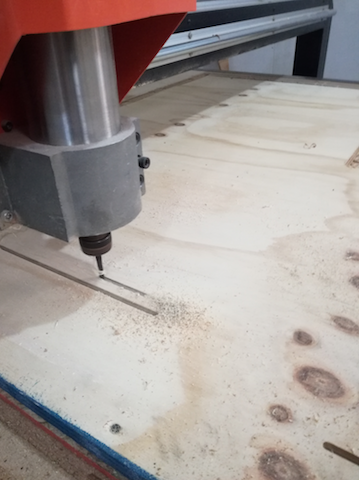
After loading the G code and making sure the origins were set, it was ready to cut. I began cutting after first making a test to make sure the drill went on the intended path. It all went well to begin with, and the pattern began to emerge
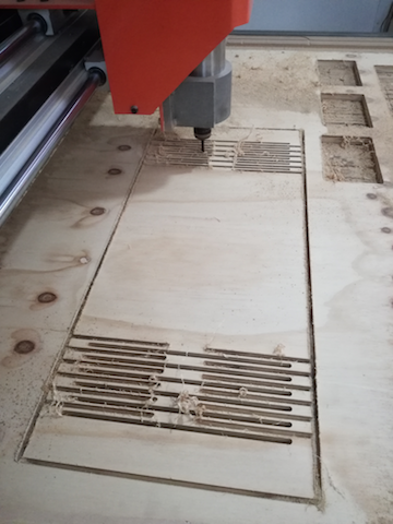
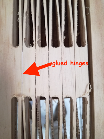
As the final pass, the kerf pattern started to become thin and chip. I had to stop the machine just at the last pass, as the kerf pattern was so flexible that it bent behind the drill as it went to make its last cut. I took out the piece, and experimented with the kerf. As you can see in the video below, the kerf hinges were highly flexible - much more than I had anticipated.
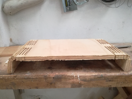
In order for the hinges to stiffen up, in order to bear the load of the desk part in between. I put a little glue in between the first few hinge cuts on either side, and then clamped it to dry
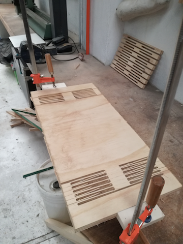
When the glue dried I tried out the desk - it stood up! Not very steadily, but much better than it was before gluing some of the hinges. I'd like to make a better designed one next time, and now I know to make the kerf a little less thin - it's amazing how flexible a large chunk of wood can be when milled in these patterns.