Week 15 - Networking & Communication
Networking, talking to our instructors and thinking of my final project I desided to do a wire network that would have a master board and two stepper motor boards as slaves. I will send commands to eather of the motor controller boards and make the motor run. On interface and applications week I can use this setup as well.
I have designed the motor controller board on output week. I will have to make an other one of those and then the master board. I will need two stepper motor control boards on my final project so I can use this opportunity to make the needed boards.
Motor controller board for networking
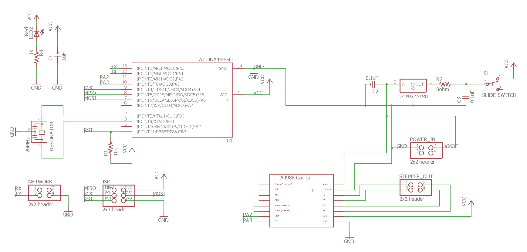
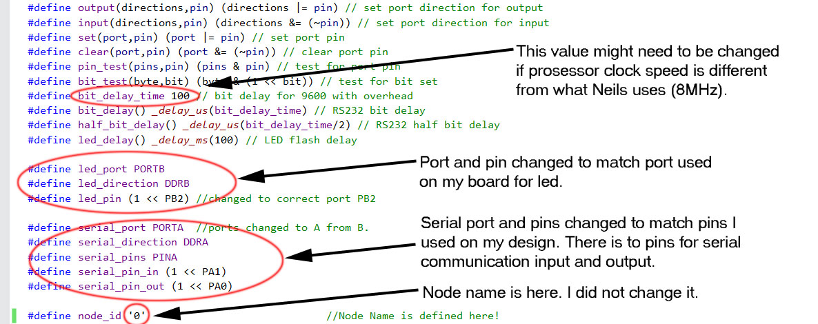
The week 10 stepper control board does not have network connectors so to make networking possible I have to make a bus for the board. To achieve this I will add 4 pin header for all board that will have power and ground as well as receiving (RX) and transmitting (TX) pins on it. After some thinking I desided to leave the power pin off the networking cable. The two motor control boards will be powered on their own as they need more power that the FTDI-USB-cable can provide. The Bridge/master board will be powered from FTDI-cable. This will mean that on the networking cable there is only RX, TX and gnd cables.
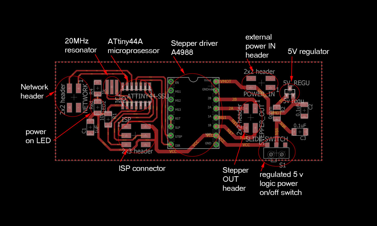
First I started editing my motor controller board. On week 10 design the board have a button on the board. I will not need that after output week so I removed that. I added networking cable connector. Also, I added a slide switch to separate the logic voltage side from the motor control side. This will give me options to power the board.
After modifying the motor controller board this is what it looks. There is network connection and logic power will come from motor board power input through 5v regulator. So there is no power connected to the network. Only TX, RX and ground. The bridge board will get power from FTDI cable.

Bridge/Master board for networking
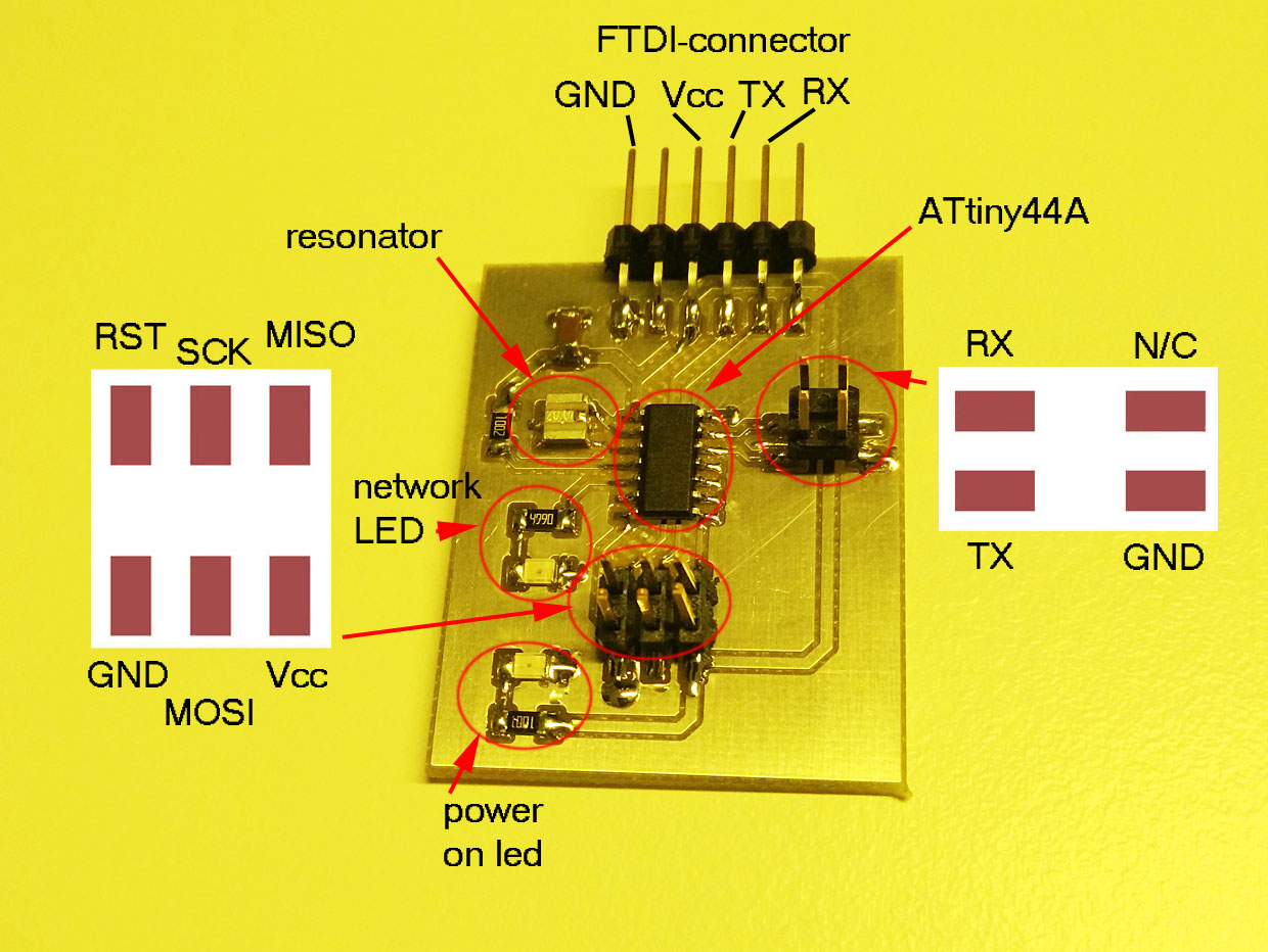
After I modified the stepper motor board, I designed the Master/bridge board that will connect to slave boards and to the computer through FTDI-cable. I will be powered through FTDI-cable and have ATtiny44A microprosessor and a led for identifying network activity. I used weekly demo boards by Neil as a guideline for my design. I used ATtiny44A instead of ATtiny45 so that all my boards have the same microchip on them. It is quite simple board. This is what it looks like.


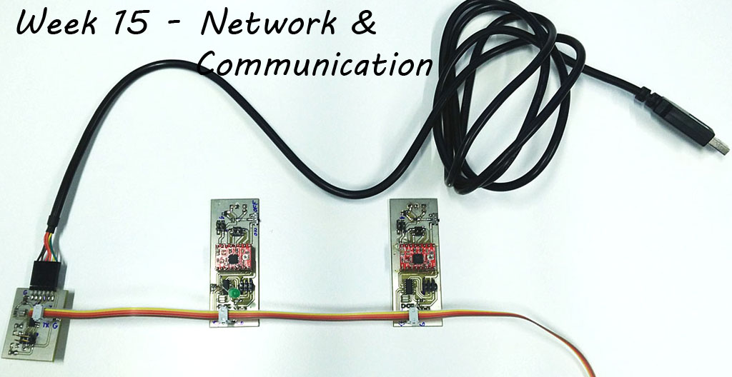
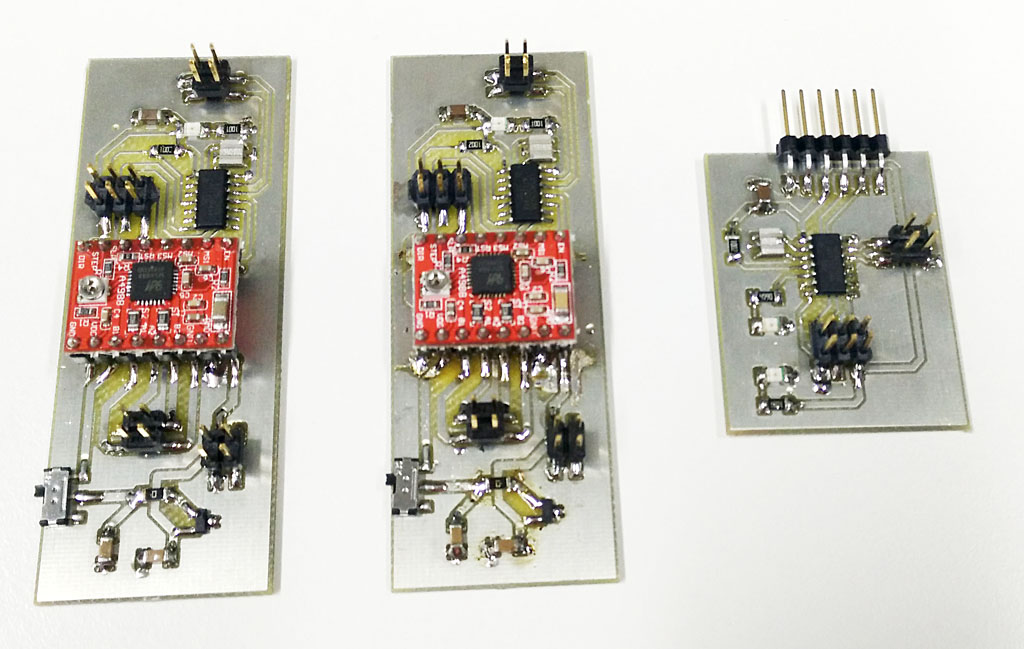
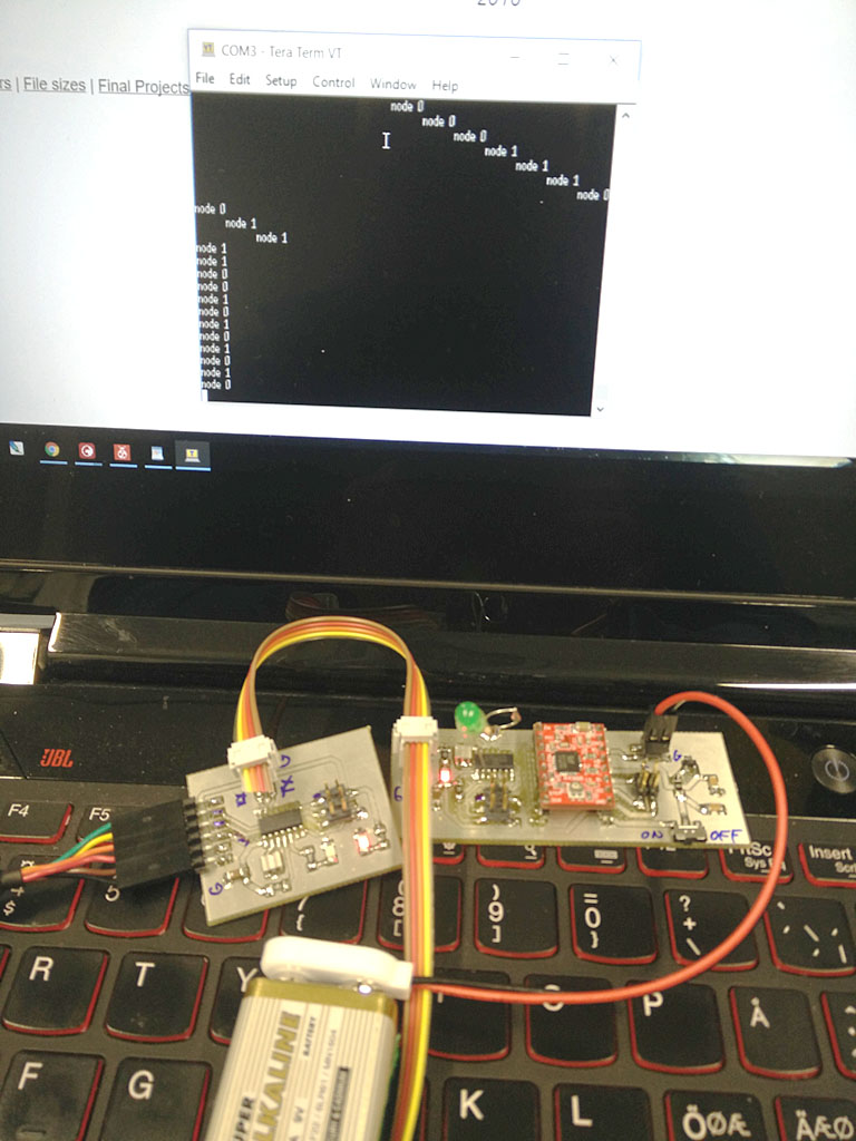
How I have all three boards that I will need for the network.
Networking, Networking...
All my problems started from here. I edited a code from one of our labs last year students Dorina. It did not work for me. I did not get stuff working. I build and uploaded the programs with right port modifications to my boards but they did not work. There was no response from terminal on anything.
After wondering and trying to figure out what was wrong, I desided to take Neils code from week 15 page. Edited Neils code to match my pin configurations and so on. And finally got it working. I am still not sure what I did wrong with the first code. Here is the process how I got it working.
What is going on there on the network???
As we have been told, this simple over cable network works so that there a two cables, RX and TX. TX means transmitting and RX receiving.
Here is the setup I need for networking setup:
- Bridge board, I will be connected to computer by FTDI-USB-cable. Board will get power from computer. I will connect computer terminal to the network cable.
- 2 pcs of slave boards, in this case stepper motor controller boards with cable network headers installed. Stepper control boards will be powered separately on their own to ensure enough p power for stepper driving. They have after production installed leds to indicate network action and node name recognition.
- Tera term terminal program installed to my computer. It is downloaded and installed from here.
- Ftdi-cable, IT MUST BE 5V cable if 5V logic voltage is used! I tried 3,3V cable with 5V logic voltage and it did not work at all.
- NOTICE! If you have unprogrammed boards on the network the network will not work. So make sure all boards connected are proberly programmed.

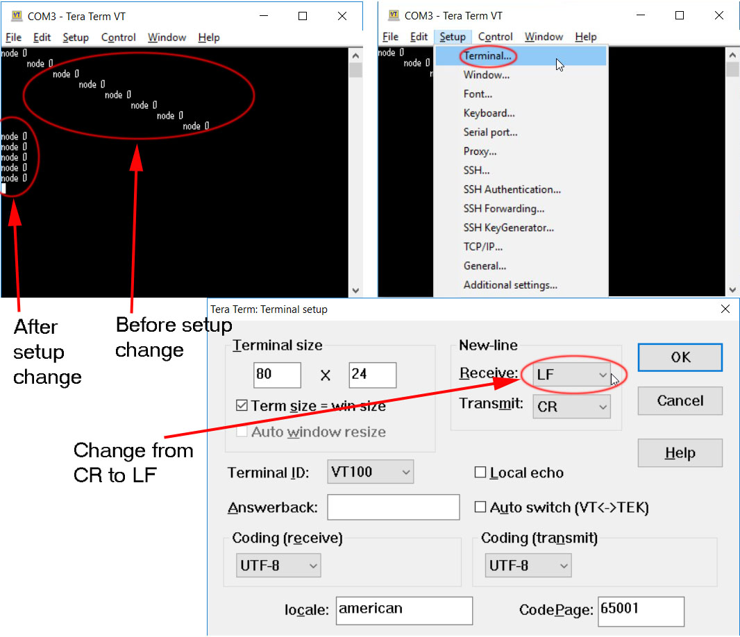
Tera Term setup
After installation, open the terminal. First you need to define Serial port. If you dont know on what port your device is on, go to device manager on Windows. In my case win 10, right click windows button -> select System -> Device Manager -> Here you can see the port your device is on. On Tera Term select correct port. In my case I have nothing else in COM-ports so Tera will give me only one option.
One fixup for Tera Term setup. From Setup -> Terminal change Receive to LF. This will help fix line changes on the terminal.
Writing the fuses on the microprosessor
After researching a little bit more I found out that ATtiny44 and ATtiny44A are basically the same prosessor. A is later version with some minor changes due to production improvements. They can be handled like they would be the same prosessor. Datasheet about that is here.
I also found out that there is an error in Engbedded for ATtiny44A fuses. As you can see later on this page, Engbedded defines ATtiny44A to have 0.9-3MHz external oscillator fuses programmed as a defaul. The ATtiny44A datasheet tells us that default settings are as they are for ATtiny44, 8MHz internal oscillator with clock divider by 8 fuse bit is on. Here is part of the 44A-datasheet page 30. Here is a link to the full datasheet.

So the defaul clock speed is 8MHz divided by 8, making it 1MHz as a factory default.
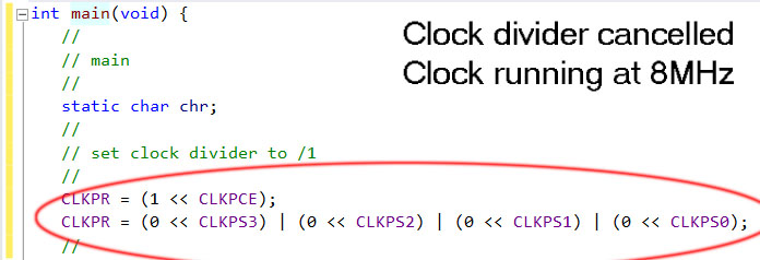
On the original code for asynchronous serial bus communication hello.bus.45.c from Neil, there is ATtiny45 runnig at 8 MHz. The default setup for this prosessor would be 1MHz. On the software he re-programs the 1/8 divider of the fuse bit off, making the prosessor run at 8MHz. Lets see from Engbedded for ATtiny45.

On Neils code there is part that cancels the divider. So at the end the prosessor is running on 1 MHz. This register change can be seen on the ATtiny45 datasheet. and on the code.
My ATtiny44A microprosessor and fuses
Instead of ATtiny45 I was using ATtiny44A microprosessor. As talked earlier unlike the Engbedded www-page definess the microprosessor is notrunning on external resonator on 0.9MHz - 3MHz but on 1MHz.
As I did not know about the error at the time, I re-programmed the fuses on my prosessor to run on 8MHz internal oscillator even I have 20MHz resonator on the board. Again from Engbedded for ATtiny44A.
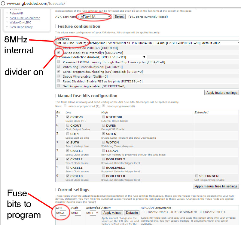
Using AVR dude I programmed the fuses. Command line command is:
avrdude -p t44 -P usb -c usbtiny -U lfuse:w:0x62:m
Now I had my prosessor running at 1MHz by fuses, but as I used Neils code as template, I had my ATtiny running at 8MHz.
I used AVR Studio to write the program and generate the .hex file. I forgot to define the prosessor speed with F_CPU command as Neil does it somewhere else than in program. Luckily I assume AVR Studio has some generalization to use that prosessor speed when not defined. I got warning message from AVR Studio but as I did not understand what was wrong and system worked fine, I forgot it.
Editing software
To make Neils hello.bus.45.c code to run on my setup, I defined the used pins to match the ones I used. It is quite easy to use Neils code, all ports and pins are defined at the start so I just changed them and rebuild the project and loaded it into the microprosessor. I use AVR dude for this. It is explained on week 8.
Of course there are three different codes that has to be uploaded to the three different boards. Only difference between them is the node_id. For the boards they are 0, 1 and 2. See picture below.
Now I was ready to run the network. I installed the network cable to connect different boards and FTDI-cable from bridge board to computer. Next started the Tera term, selected correct port and typed 0, 1 or 2 on the console. I worked finally nicely. Here is a picture and a video of the feat!
Video of two part network running
Files used with this weeks assignment
Eagle .sch-file for Bridge board
Eagle .brd-file for Bridge board
Gerber274X .top-file for Bridge board
Gerber274X .out-file for Bridge board
Eagle .sch-file for Stepper board
Eagle .brd-file for Stepper board
Gerber274X .top-file for Stepper board
Gerber274X .out-file for Stepper board
Excellon .drd-file for Stepper board
main_bridge.c file for Bridge board
main_slave1.c file for Slave1 board
main_slave2.c file for Slave2 board
network_bridge.hex file for Bridge board
network_slave1.hex file for Slave1 board
network_slave2.hex file for Slave2 board