Week 10 - Output devices
This weeks assignment was to make a circuit that can control something i.e. output device. For my final project I will need to control stepper motors, so I decided to make a stepper motor controlling ciruit board. As we have been using ATtiny44A on our led blinking projects I had a good starting point to use the same chip. As well, our local FabLab had some A4988 based bipolar stepper motor controller header boards in stock and one of the supervisors suggested that I could use that as part of my board. So I desided to do that.
The A4988-carrier board that I am using on this weeks project is like this one at Pololu. The page has nice explanation of the function of the carrier. The actual stepper motor driver chip is made by Allegro and the datasheet for the chip can be found here under Pololu page.
The A4988 bi-polar stepper motor driver chip is using H-bridges to control the motor. I can be used as 1 step, 1/2 step, 1/4, 1/8 and 1/16 -step modes. Controlling the motor is made really easy and needs only steps selection, direction selection and rising pulse edge step command. For my trials on this week, I will only need to use the direction and step initiation commands. This makes programming the stepper operation quite easy.
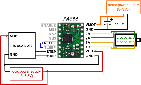
Here is the A4988 carrier board schematic and minimal wiring needed to run it with some controller. I my case I will use ATtiny44A microprosessor.

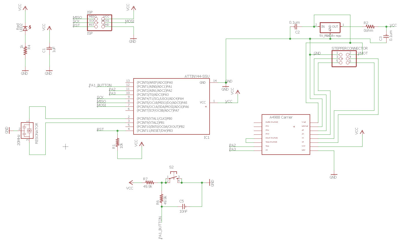
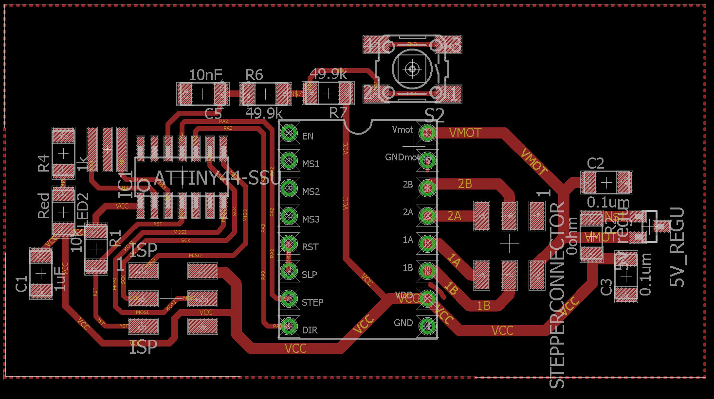
To get this thing done I had to design a pcb that would house the a4988 carrier and attiny45A microprosessor. Using Eagle pcb design tool I draw this board. On the right is houses a 5 V regulator, to get logic voltage out of stepper motor power source. A connector to connect the power input as well as 4 sockets to connect the stepper motor controlling wires. I am not sure if it is a good idea to put them on same connector but that is what I did. On the center of the board there is a place for the A4988 carrier board. Left side of the board has ATtiny44A and all its components. Also ISP connector for programming the microprosessor. I did not add other power input option for the board except the regulator from the main power input. This means that I have to connect a power source that has more than about 6.5 V input voltage for the regulator to work correctly and drop the voltage to 5 V for the microprosessor. From the 5 V regulator datasheet the over regulator drop of the voltage is 1.2 V. This is why about 6.5 V or more is needed. Of course if the ISP-programmer provides power for the board for programming, then extra power is not needed. Currently I dont have a ISP-programmer that would do it, so I will have to use external power source.
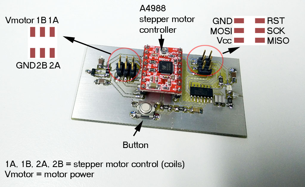
After getting the board done, I soldered the components on it. Some extra space would have been nice on the left side of the carrier board, next to the header. I soldered the header first and after that it was I bit extra work to get the header pins soldered. Here is the board explained.
After that I connected the power for the board... and burned it. Something was wrong with the board. I was pretty sure that it was not a short at least not power/ground short as I measured it before. Anyway, the carrier board got really hot and I unblugged the system from 9 V battery I was using to power it. As I had no idea what was the problem I removed the carrier board from my own. That was I bit too forceful operation and some of the pads got ripped of.
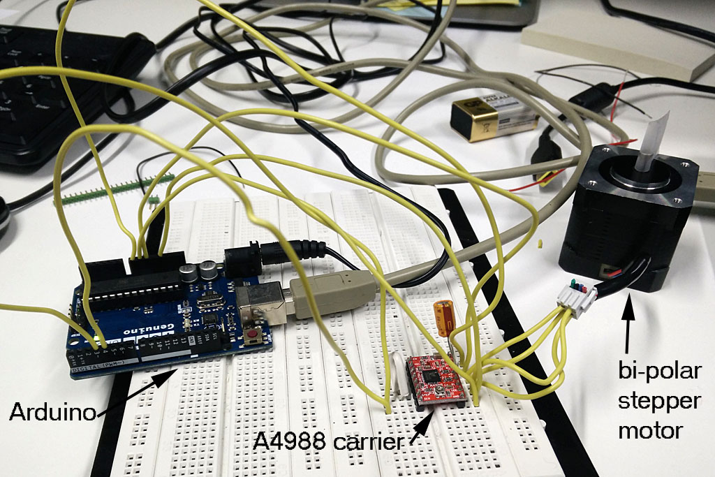
To solve what was wrong, I decided to test the A4988-carrier boards operation separately. To do that, I got a good advice to try it with Arduino board and programming environment.
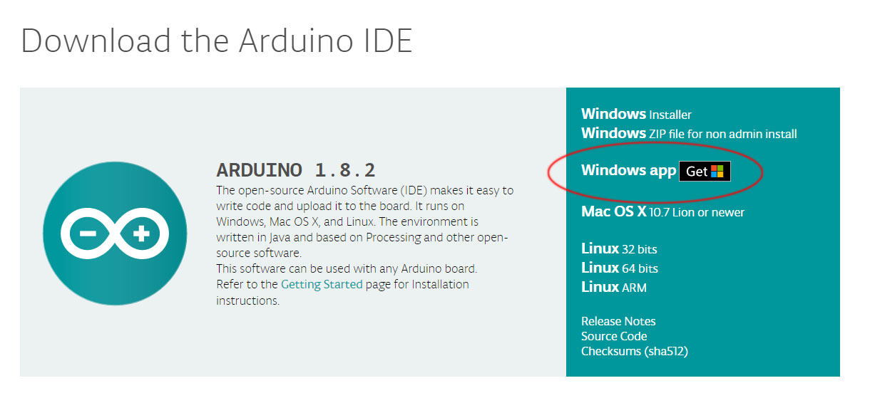
Installing the Arduino environment was suprisingly easy. I googled "Arduino IDE" and got straint into Arduino page and installed the windows version.
Now I made at test setup I found from How to mechatronics-www page. I also used the example code for Arduino from the same www-page. I also tested Arduino library stepper motor test code. That code is at the end of the page.
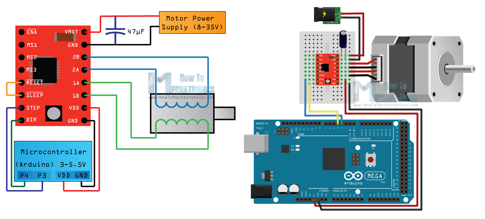
This is what it looked like.
On this setup and the software example from the same page, all worked on some extend. The program should have run the motor 360 and back but on my case it only moved a little to eather direction. I assume it was due to the fact that all power came from arduino and I was not enought. But that did not matter, now I knew that basically the setup should work.
Now I wanted to know if my own boards logical part, i.e. the software and microcontroller in general would work. As I broke to board partly earlier when removing the carrier, I had to adapt to the situation I did not have a now board ready yet. So I made the following setup.
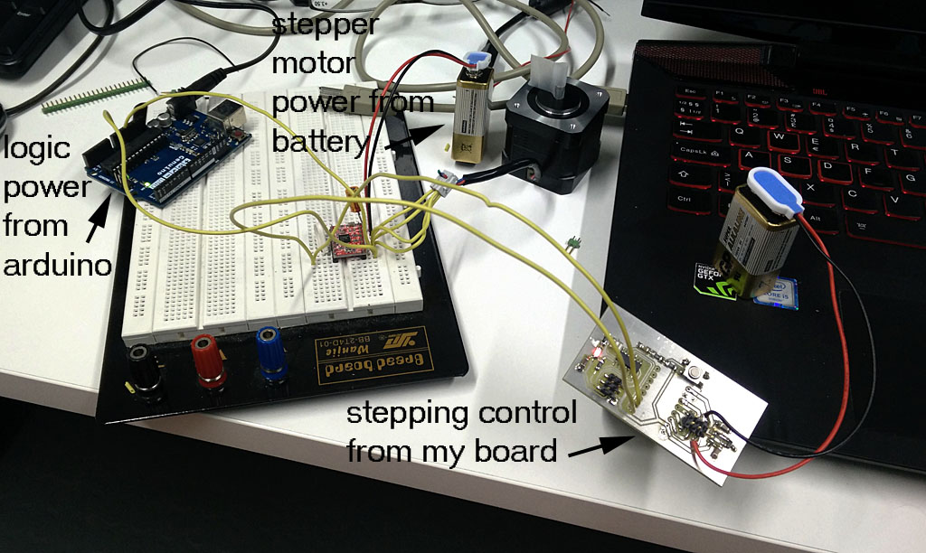
Most annoying part was to power everthing correctly. I ended up powering my own board with 9 V battery and the 5 V regulator on my board. The A4988 logic power came from arduino's 5 V output and arduino was powered from wall socket. And at the end 9 V battery was connected to the A4988 motor power input connectors. It is a mess but ok for this fast test I wanted to do.
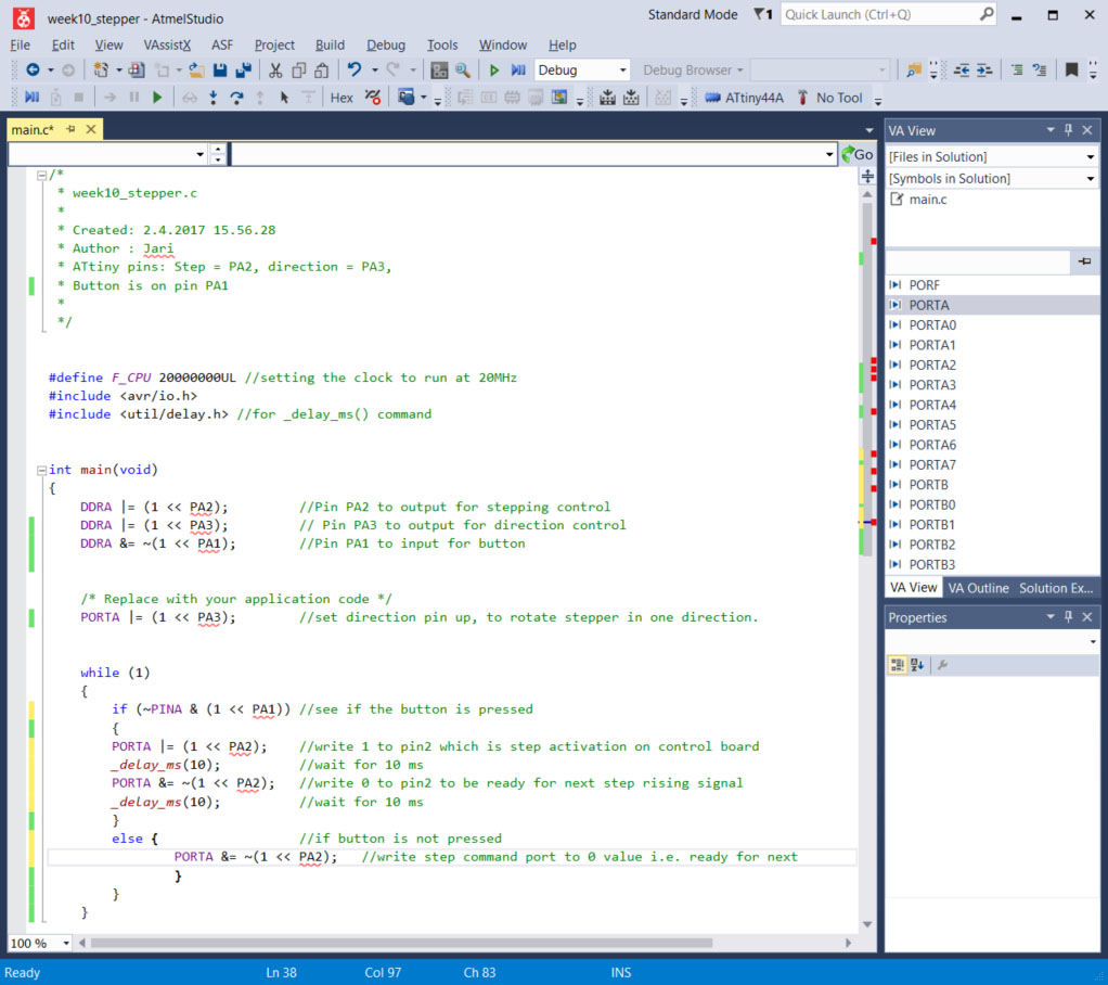
At this point I had written a simple code to ATtiny44A I was using. It only rotated the stepper motor a bit forward, stopped and then rotated it again. On the example code here, I am commanding the A4988 step and direction pins. A4988 makes all the necessary signals for the stepper to make the steps. On this case Step control pin is connected to pin PA2 and direction selection pin has been connected to pin PA3. This was just to test the electronics I had build. The setup worked.

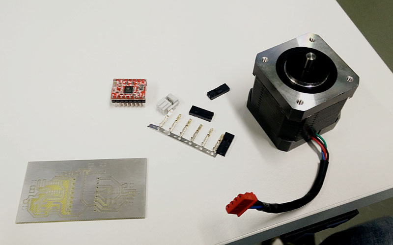
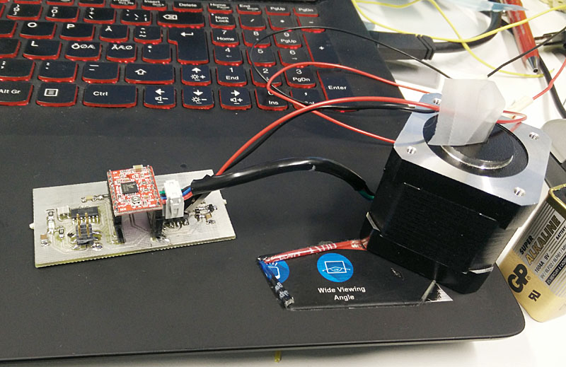
After testing the board for general workings I made a code that when I press the button motor runs.
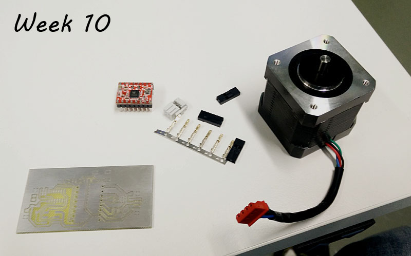
Here is the final board and bi-polar stepper motor.
After all this and soldering a new A4988 header board to my own design, it started to work. I assumed it was a short circuit on my board that got removed when I changed the header board.
Few weeks after I finally found out what was the original problem with my board. Of those A4988-board ordered from somewhere for Fab Lab use some were not working to start with. They had short ciruit between power and ground to start with. So the reason I burned the board on my first try was that the A4988 header board was in short circuit. I found this out while doing the networking weeks assingment.
I use updated version of this stepper motor control board on my final project. There are two of these running lateral and vertical movement. See the final project page.
Files used with this weeks assignment
Stepper C-code
Gerber file .top
Gerber file .out
Gerber file .drd
Eagle .sch file
Eagle .brd file
Arduino stepper code from Arduino example .ino file