Assignment 3
8.2.2017
Topic: Computer-Controlled Cutting
1. Laser
- make laser cutter test part(s), varying slot dimensions using
parametric functions, testing your laser kerf & cutting
settings (group project)
- design, make, and document a parametric press-fit construction
kit, accounting for the laser cutter kerf, which can be
assembled in multiple ways.
Learning outcomes
- demonstrate and describe parametric 2D modeling processes
- identify and explain processes
- develop, evaluate and construct the final project.
2. Vinyl Cutter
- cut something on the vinyl cutter.
Learning outcomes
- identify and explain processes
- design and create the final
project
Include your design files
and photos of your finished project
Picture note: At first, I increased the
picture size. I will use about 900 dots width and 72 or 96 dpi
resolution.
Lecture note: The Laser MicroJet
combines water jet and laser, and makes hot laser cold (http://www.synova.ch/technology/laser-microjet.html,
http://www.itw-chemnitz.de).
Vinyl cutter
I use Roland GS-24 desktop cutter here. It is located right in
following picture. The control computer locates left, where the
cutter is connected by USB cable.
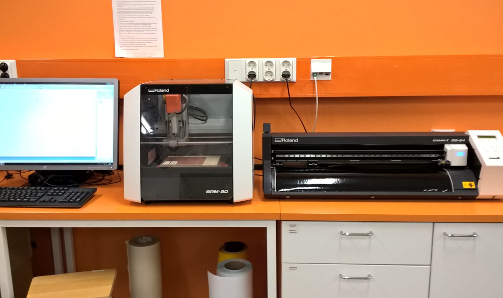
I lifted a black roll of paper to the back of cutter. It has stand
there. And, I loaded the paper in. Important thing is the lever in
left side of cutter, which locks the paper in place.
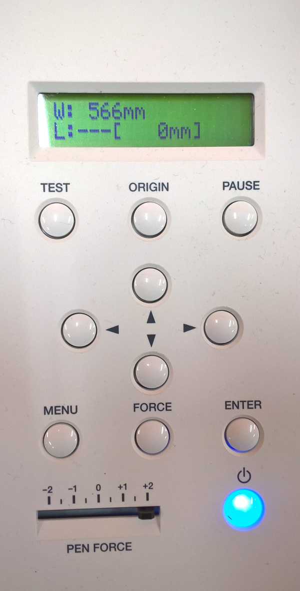
Then, I switched on the cutter. I selected sheet as roll and
control panel shows cutting area as in following picture.
The control panel is very easy to use. You can test cutting, set
origin and pause cutting.
Pen force setting controls the cutting depth. Blue button switch
cutter on and off.
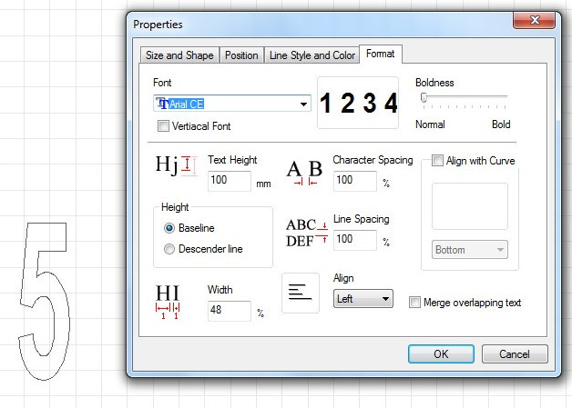
I used cutStudio program for my first cutting. My idea was big
numbers 1 to 9. I used text tool to write numbers 1 2 3 4 5 6 7 8 9
to the bottom of the sheet. Then, I selected them and changed the
text height to 100 mm as my plan. I selected font as Arial CE. Other
parameters were as default.
Then, I set cutting area by reading dimensions from machine.
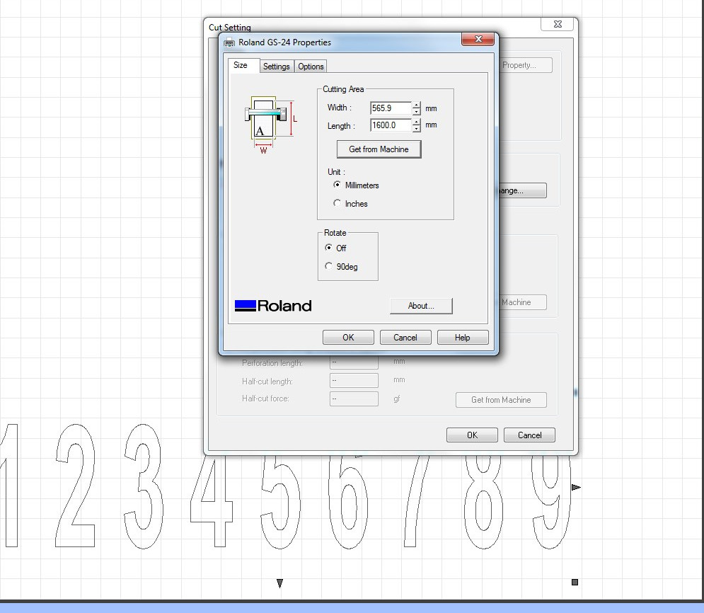
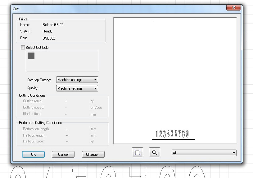
Then, I selected cut command from menu, checked parameters, selected
OK and cutter started to work.
Cutting 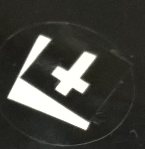 gone too deep in sheet.
Therefore, I tuned the pen force to set the cut depth correctly.
gone too deep in sheet.
Therefore, I tuned the pen force to set the cut depth correctly.
Following picture shows correct test results.
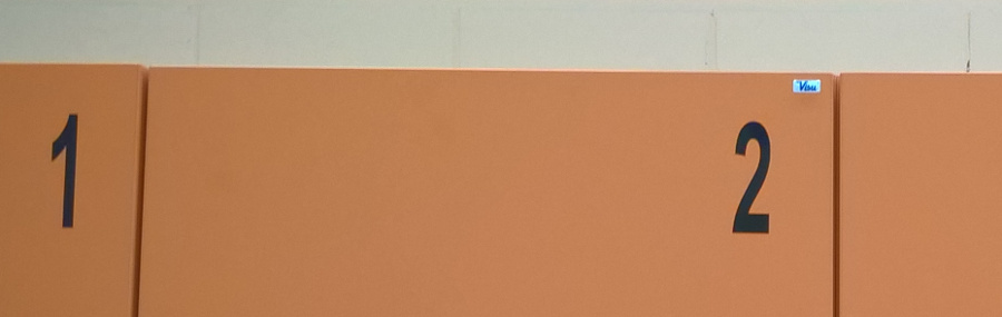
After all, my cuttings went well. I needed these numbers in our
laboratory as showed in the picture.
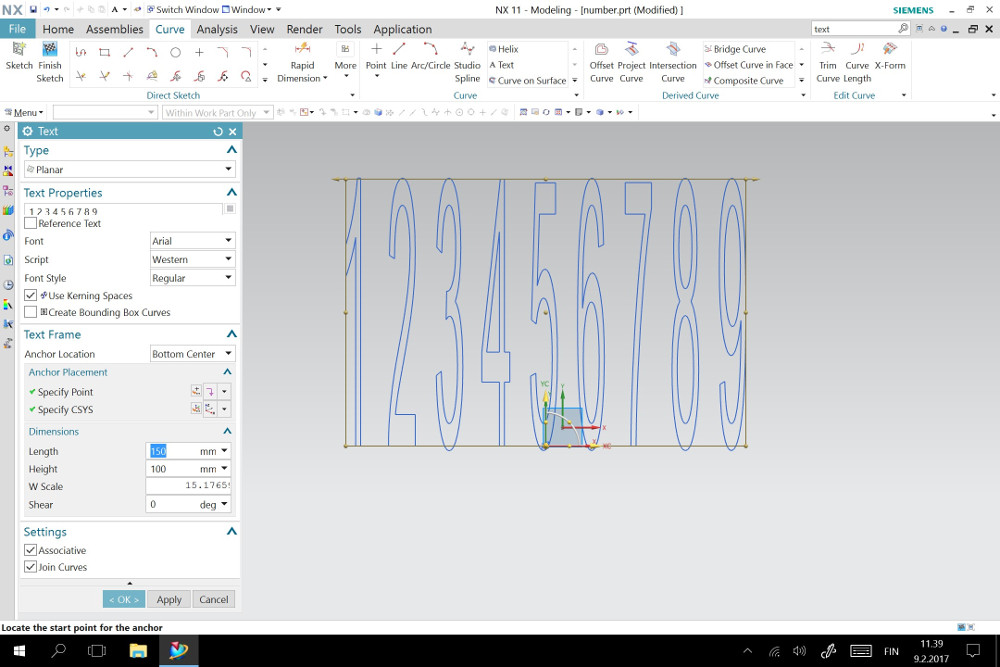
Also, I made the second cutting study using data from NX11 program.
I created new file, selected xy plain view as my work view, selected
curve and text from menus. And, I inserted numbers 1 2 3 4 5 6 7 8 9
in place with height of 100 mm and length of 150 mm. Other
parameters were as defaults.
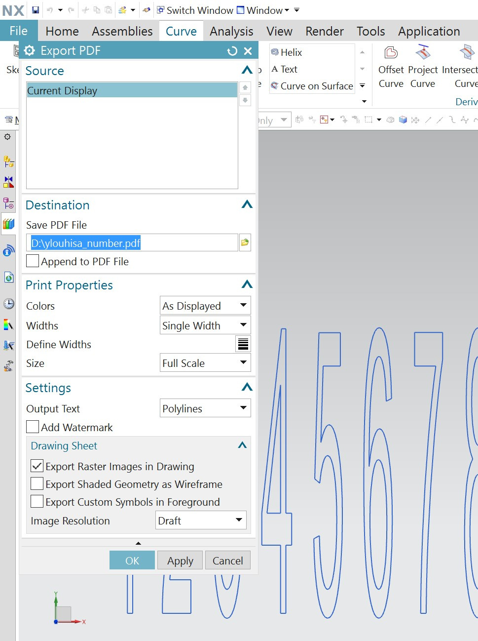
Then, I exported my drawing as PDF file.
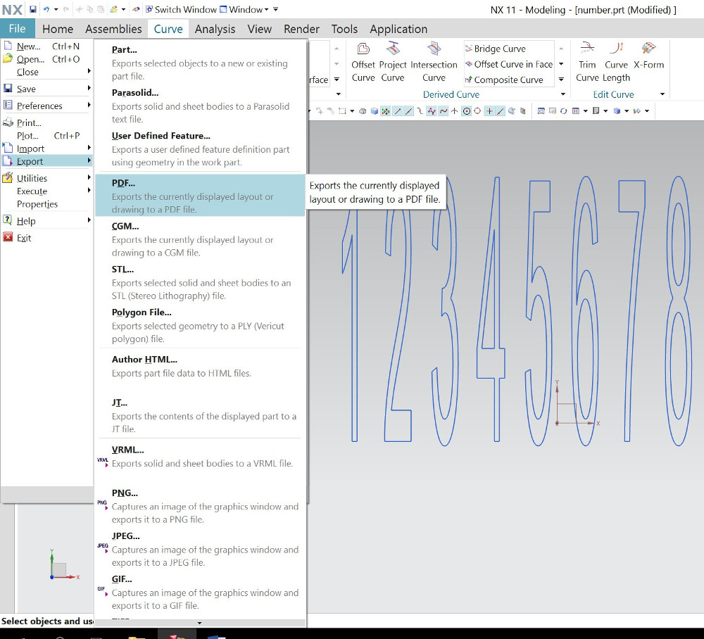
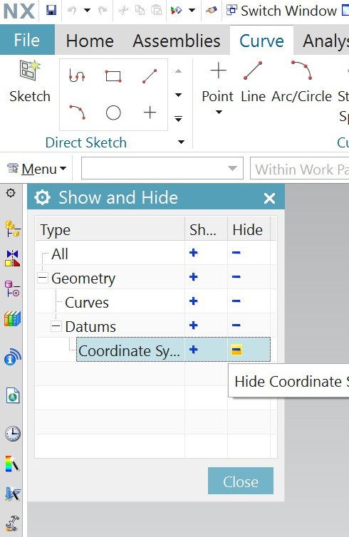
However, I must hide coordinate icon before exporting.
Here, I do export. Line thickness is same for all geometry and it's
value is 0.25 mm. It is not critical for vinyl cutting. Only vector
graphics is needed.
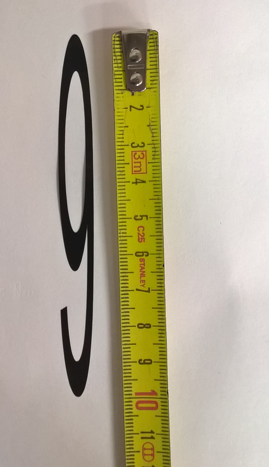
I opened the PDF file in control computer, selected print and again
the printer as Roland GS-24. I must change cutting length to 200 mm
in printer properties to ensure cutting to the bottom of the sheet.
Finally, I checked the size of my numbers. They are in order.
Laser cutting
I used Epilog Fusion laser with 75 Watts of power.
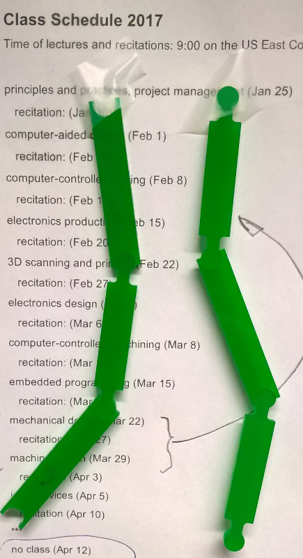
At first, I drew a sketch, what I would like to do. And, I decided
to cut a chain of bars which are connected together by snap-on
connectors. Also, I do them parametric by length series and
connection details.
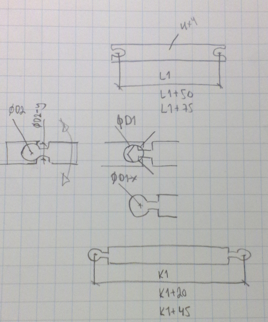
Here, I have a first computer sketch. I want draw all as one
assembly and develop my idea ready first. I want use 3 or 4 mm PMMA
sheet as my material.
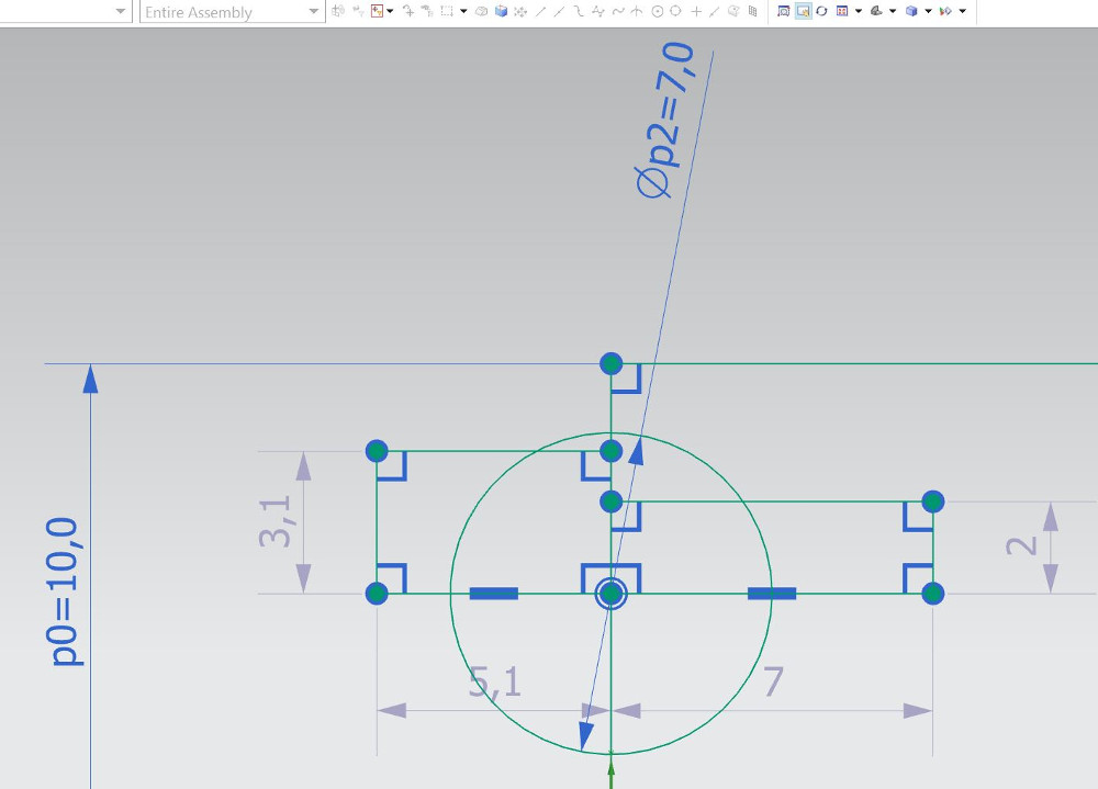
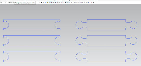
Then, I mirrored my geometry, but I needed two reference lines
to do it. Horizontal line mirrors the upper details down.
Vertical line mirrors the geometry right to left. Several mirror
operations got the geometry almost ready.

I tested the parametric features after mirroring. The middle and
left circles are mirrors of right circle and the size follows each
others.
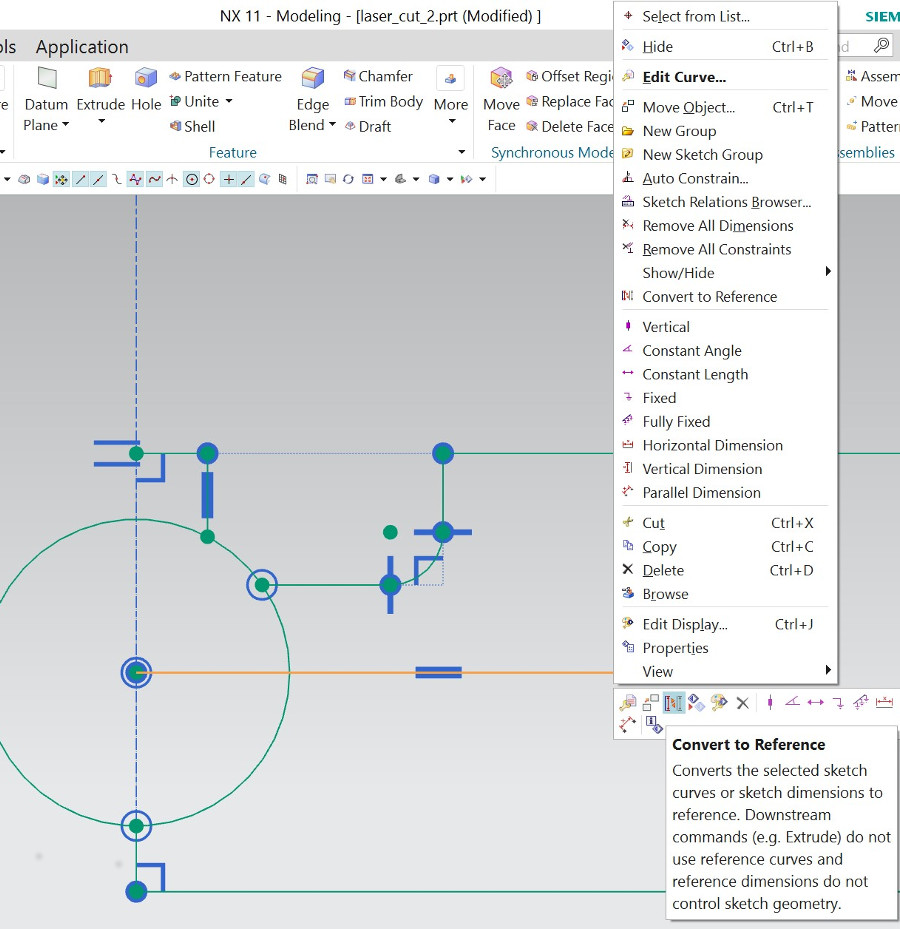
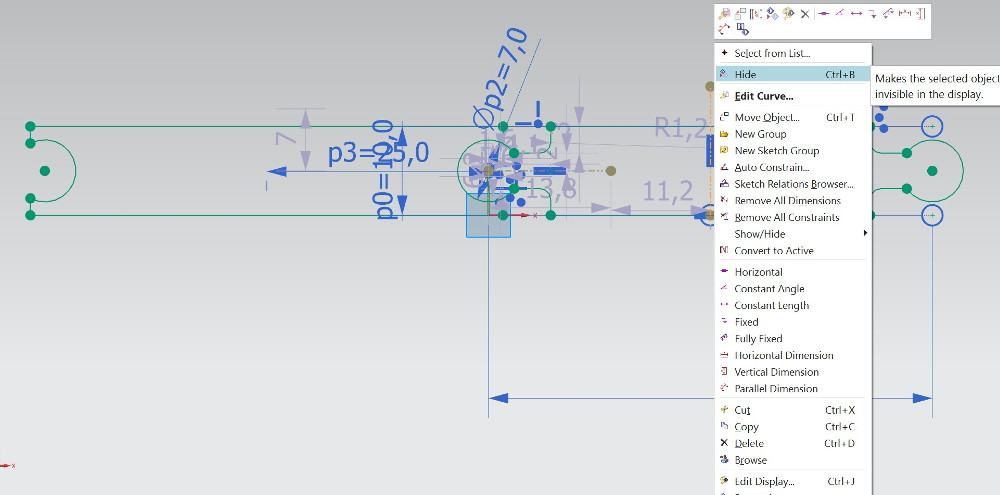
Now, my first laser cut drawing is ready Only, I must hide
unwanted details, such as dimensions, dots and reference lines.
At first, I want test the snap feature, which are correct dimensions
there. Then, I made final drawings for my chain of bars. Therefore,
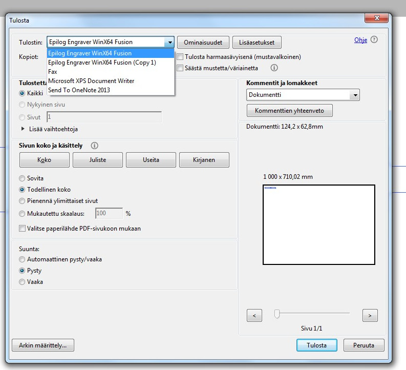
I made PDF file as earlier, but defined the line width as 0.02 mm. I
opened the file in laser control computer and selected printer as
Epilog Engraver WinX64 fusion.
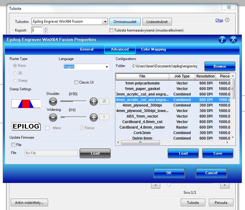
Then, I selected properties and from advanced tab I selected the
ready set parameters for 4 mm PMMA (Acrylic) material.
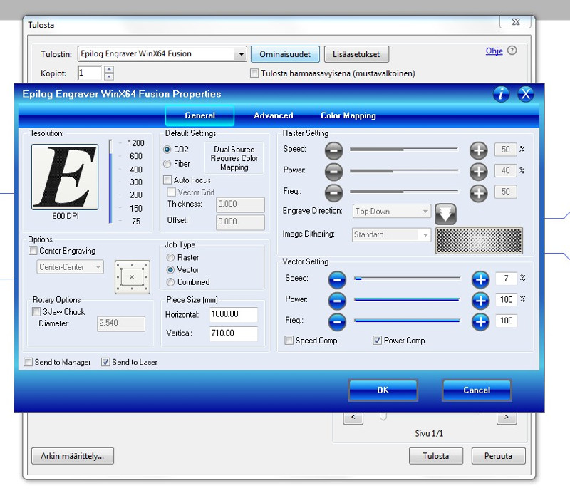
General tab shows all cutting and engraving parameters as following.
I can also tune them. I pressed ok here and print in next window.
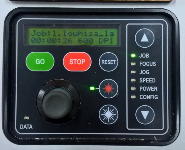
Then, I used laser control panel. I done final selections from right
menu by pressing up and down arrows. I used jog to move laser beam
there I want it to start. Jog confirmed by pressing the joystick.I
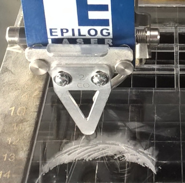
used focus to focus beam to the correct level as triangle tool
guided. And finally, I pressed GO.
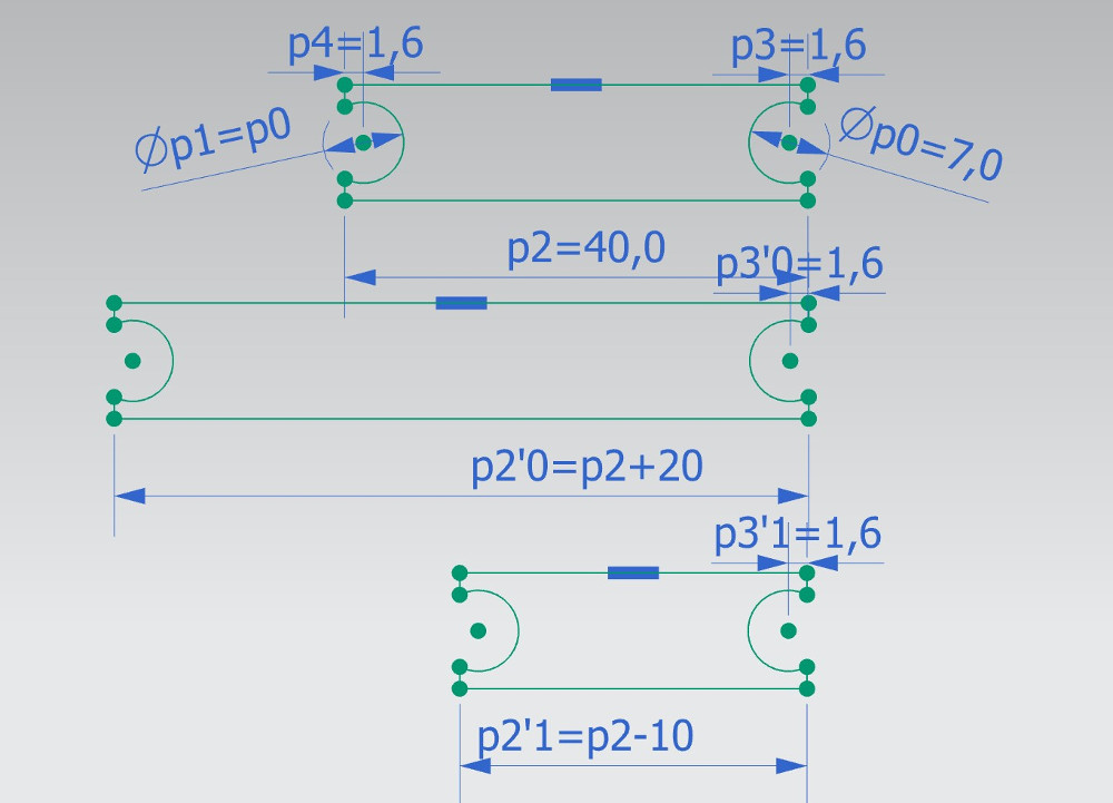
My first laser cutting is ready. I measured the snap joint details.
The hole diameter was 7.1 mm and the head diameter 6.9 mm. The
original (nominal) diameter was 7 mm in my drawings. Therefore, snap
nominal diameters must be 7 mm for the hole and 7.25 mm for the head
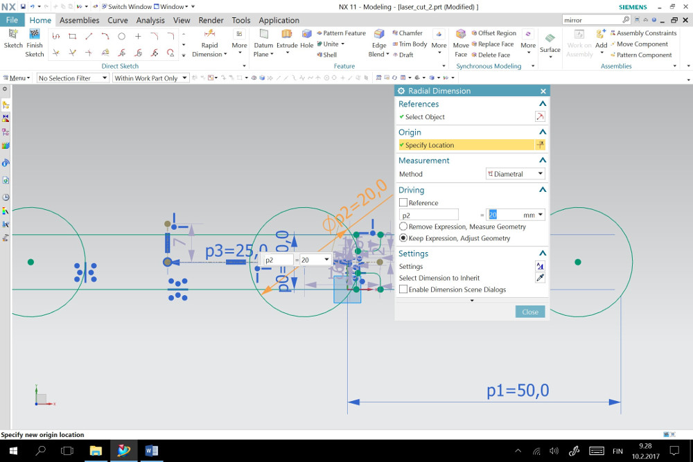
for tight connection. I can parametrize them and also bar
lengths as presented is following picture, diameter p1 = p0, length
p2'0 = p2+20 and length p2'1 = p2-10.
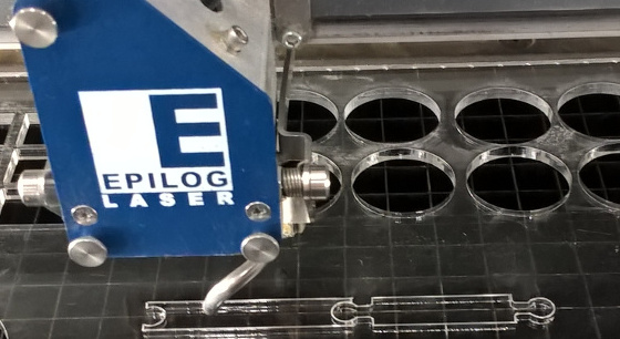
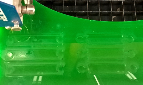
The final parts were drown as separate parts to the same sketch.
They was cut of green 3 mm PMMA material. The snap feature was
working well.
Group work
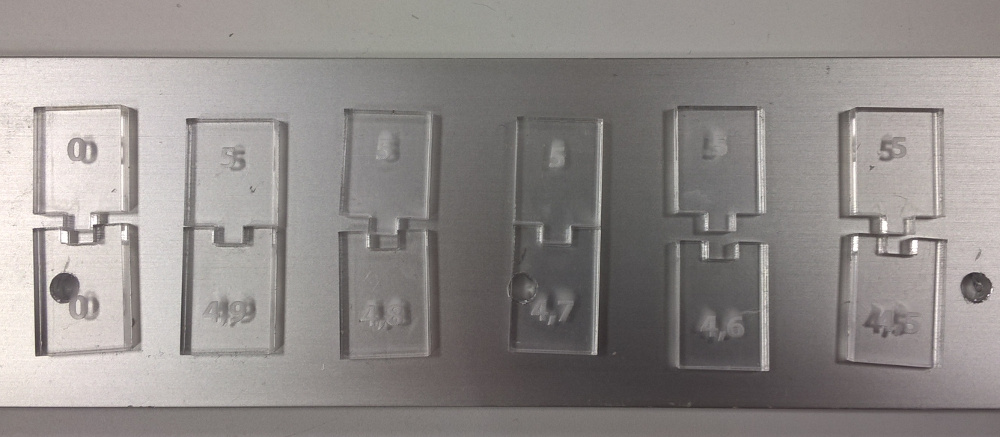
I made also a kerf study as group work with Eino.
We used 3 mm transparent PMMA. The most left parts were cut
together. Others separately. Numbers in parts mean nominal
dimensions in drawings. The best fitting pair was 5/4.8 mm. Kerf
diameter should be then 0.1 mm. This confirm also my earlier
studies. However, we found some tracks were not in right angle (90°)
as supposed and this may cause errors. Reason for that is unknown.
Maybe material had some defects. Eikka has documented also our
results in his page (http://archive.fabacademy.org/archives/2017/fablaboulu/students/73/FabAcademy_Eikka/Assignment_3.html).
Final project
In this case, I can not do any enhancements to my final project.
However, this study was useful. I seldom needed these parametric
features earlier. Now I can do them with NX.
My NX CAD files are here: vinyl cut and
laser cut.
These also in DXF format are here: vinyl
cut.dxf and laser cut.dxf.
CutStudio file is here: numbers_cut.cst.