Assignment objectives:
* Make lasercutter test part(s), varying cutting settings and slot dimensions.
* Cut something on the vinylcutter design
* Make, and document a parametric press-fit construction kit, accounting for the lasercutter kerf, which can be assembled in multiple ways.
Neil's class Summary
Lasercutting
We were led by Matias Mangado, our master of inventions at Synergy Tech, in the principles, manipulation and functions of the local CNC.
We learned the basic procedure for using the Trotec cutter: Turn the power on, level the laser, activate the air-extraction system, print from the raster design software to Trotec Engraver v10.4.0, once in Trotec JobControl X drag the task into the working panel, check for material cut and engrave options in "Material Database", finally calculate the estimated time and hit "Play" button to start cutting.
 Instead of testing cutting parts in abstract way i decided to use the assignment to sketch a potential project: a press-fit construction analog camera.
This sites where very useful in my designing process:
Mr Pinhole
Light photography exposure calculator
Lomography
Paint Can Camera
The Focal Camera
How To Build a Matchbox Pinhole Camera
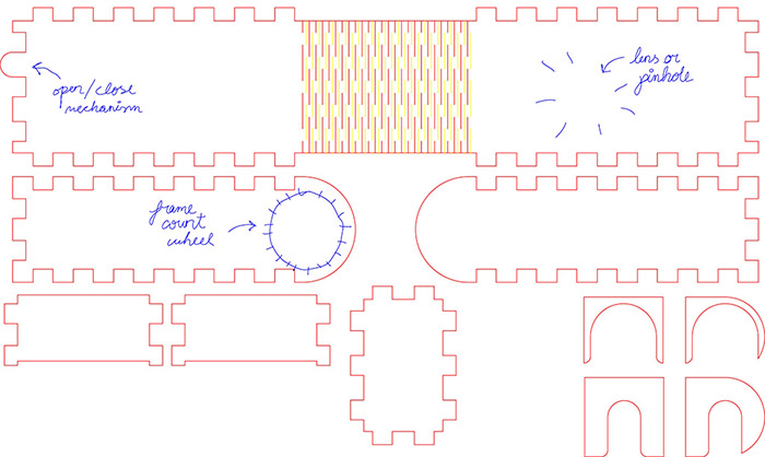
 I made some quick sketches, drawed a simple tabbed box in Inkscape with
Tabbed Box Maker
extension, edited the geometry in Autocad for an accurate dimensions control and lastly added some hand writing instructions using Inkscape to be engraved in the plywood sheet.
I made some quick sketches, drawed a simple tabbed box in Inkscape with
Tabbed Box Maker
extension, edited the geometry in Autocad for an accurate dimensions control and lastly added some hand writing instructions using Inkscape to be engraved in the plywood sheet.
 This is the Trotec's cut and engrave settings for that layout.
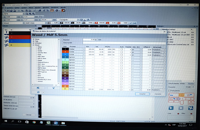
 A couple of hints. For cutting a 5.5mm thickness plywood i set a new cut layer (Red layer #2) with power at 100% and velocity at 0.45. For engraving we have two options: set a engraving layer (Black layer #1) with power at 100% and velocity at 40 or set a new cut layer (Blue layer #3) with power at 100%, velocity at 30 and Z-Offset at +5.00 to obtain a blurry engrave effect (+ represents more distance between laser and plywood, - represents a closer one, it is not recommended to work with negative values). I also added some partial cuts to the bent zone in order to make the piece more flexible, i set a new cut layer (Yellow layer #16) with power at 100% and velocity at 2, that should cut about 3mm of the whole 5.5mm thickness.
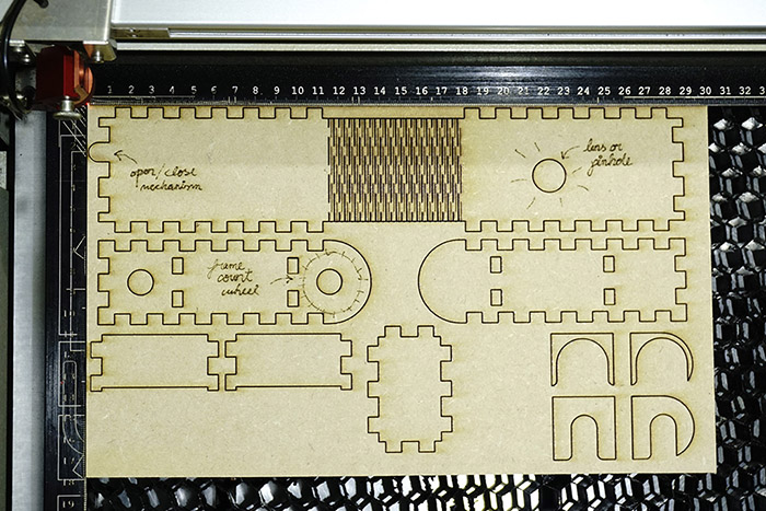
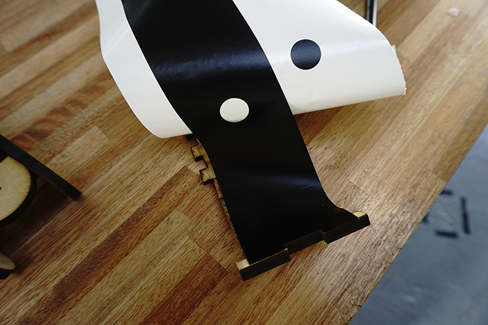
Fortunately the cut and engrave pattern in the bend area successfully works allowing a 180º flexure with 20 mm of radius in a 5.5mm thickness plywood and the most important thing: light doesn't reaches the inside.
A couple of hints. For cutting a 5.5mm thickness plywood i set a new cut layer (Red layer #2) with power at 100% and velocity at 0.45. For engraving we have two options: set a engraving layer (Black layer #1) with power at 100% and velocity at 40 or set a new cut layer (Blue layer #3) with power at 100%, velocity at 30 and Z-Offset at +5.00 to obtain a blurry engrave effect (+ represents more distance between laser and plywood, - represents a closer one, it is not recommended to work with negative values). I also added some partial cuts to the bent zone in order to make the piece more flexible, i set a new cut layer (Yellow layer #16) with power at 100% and velocity at 2, that should cut about 3mm of the whole 5.5mm thickness.
Fortunately the cut and engrave pattern in the bend area successfully works allowing a 180º flexure with 20 mm of radius in a 5.5mm thickness plywood and the most important thing: light doesn't reaches the inside.
The tabbed solution for assembly the different pieces seems to work ok.
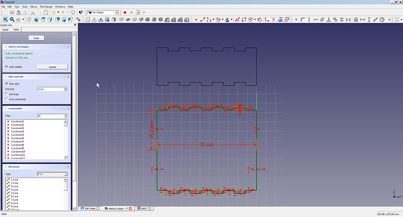
I decided to parameterize the tabs using Freecad. The inserts will depend on the height of the wood to be used, and that value will be stored for change in a spreadsheet.
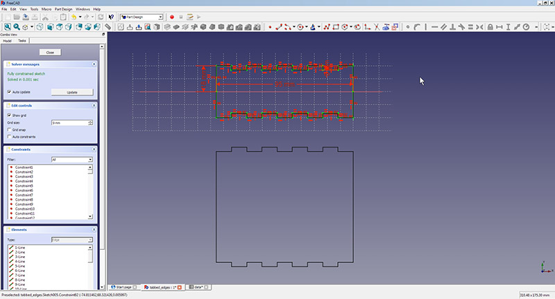 Finally, i reached a first clean and close solution for an analog press-fit construction camera. I named it: Up & Down camera. It is designed to use a pinhole as lens (radius: 0.2mm) and works with a 35mm film.
I plan to share the final design sheets and other relevant information after testing the camera in the field. Please follow
this link
for tracking the progress.
Download the files.
Vinylcutting
For testing the vinylcutter i decided to cut a simple piece of black vinyl to adhere in the inside cavity of the camera and help the light not to got in.
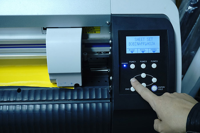
 These are the steps for using the vinyl cutter.
1. With the machine off, lift the rollers, place bobbin or vinyl sheet, relocate and lower rollers.
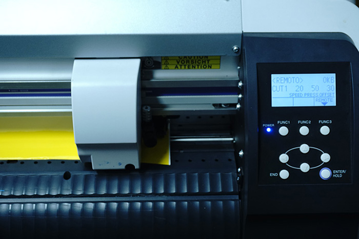
2. Turn on the machine: It will automatically measure the width of the sheet or coil and after a few seconds will return that value in the display.
3. Then we must establish whether it is a bobbin or vinyl sheet.
 4. Then ask if we want to use the marks, press the END button.
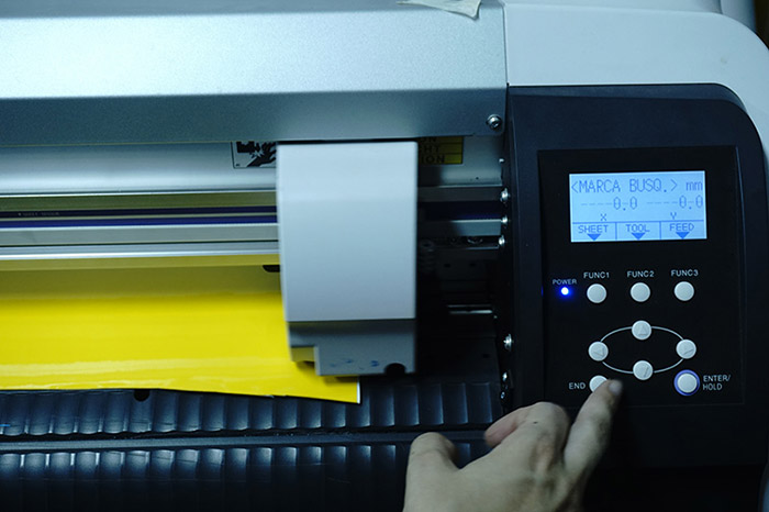 5. The machine is set to the "Remote" function waiting for the job to be sent.
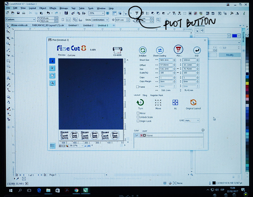
 6. Now in CorelDraw, we set the size according to the measurement obtained in step 2. We always work in Wireframe view. (View Menu / Wireframe).
7. Plot / Initialize.